Architectural Frameworks to Leverage Ventilation Protocols into Software
Quick and Easy Guide to Initial Ventilator Settings and Rapid Diagnostics
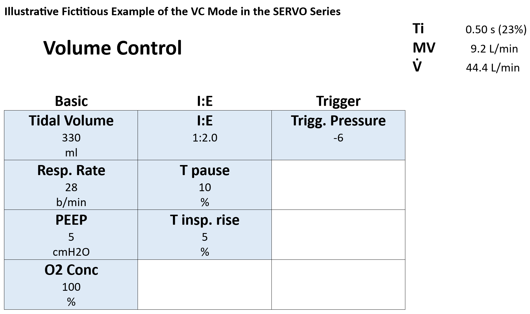
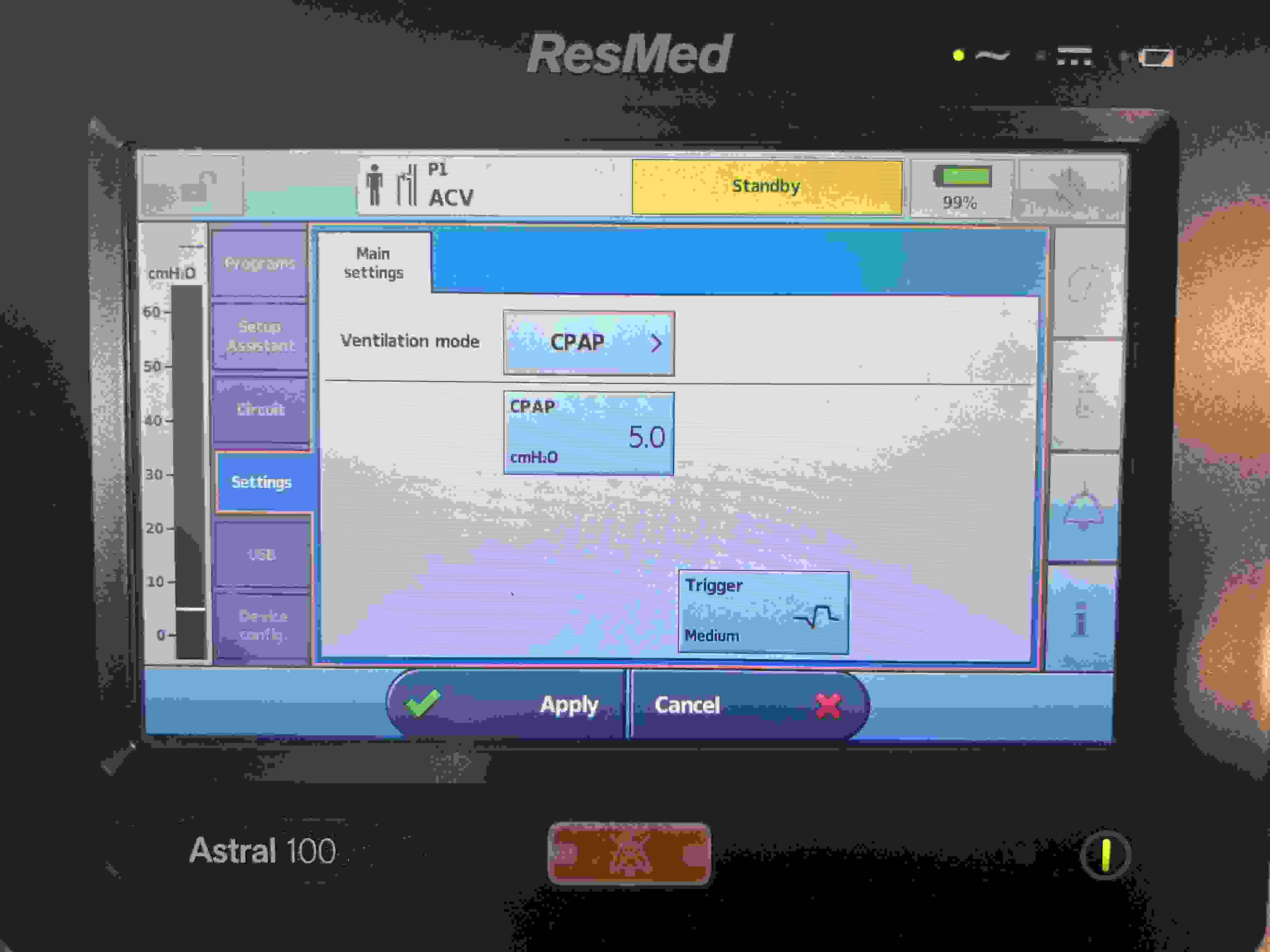
Magical VC Setting FiO2 100-PEEP 5-RR 15-TV 400: In Volume Control (VC) mode, initial settings such as FiO2 at 100%, PEEP at 5 cm H2O, a respiratory rate of 15 breaths per minute, and a tidal volume of 400 mL provide a foundational approach for the management of mechanically ventilated patients. These parameters serve as starting points and must be finely adjusted based on the patient's specific needs and responses, with ongoing monitoring to ensure optimal outcomes.
MV without Referring to PBW: While minute ventilation (MV) calculations ideally utilize predicted body weight (PBW) for accuracy, emergency clinical scenarios might necessitate quick estimations without immediate access to detailed PBW tables. Under such circumstances, a rough MV can be quickly calculated based on the patient's weight: approximately 5 liters per minute for a 50 kg patient, 6 liters for a 60 kg patient, and 7 liters for a 70 kg patient. These preliminary estimates are vital for initial ventilator setup, requiring subsequent adjustments as more information becomes available or as the patient's condition evolves.
Lung Condition Without Cdyn but Quickly Using Plateau Pressure: Dynamic compliance (Cdyn), a detailed measure of lung condition, typically considers values greater than 50 mL/cm H2O as normal, while lower values suggest potential ARDS, necessitating further diagnostics like chest X-rays. However, measuring Cdyn involves time-consuming inspiratory and expiratory holds. A quicker clinical alternative is to observe the plateau pressure. If the plateau pressure, based on an accurate MV computation per PBW, remains below 30 cm H2O, it suggests that the lungs are likely not severely compromised, indicating that the current ventilatory support is within safe limits and avoiding undue lung stress. If the difference between the peak pressure and plateau pressure is less than 5 cm H2O, it may indicate that the lung condition is within an acceptable range.
PEEP Setting Adjustments Based on Chest X-ray Findings: A clear chest X-ray typically warrants a PEEP of 5 cm H2O, while mild, moderate, and severe infiltrations might necessitate settings of 10, 15, and 20 cm H2O, respectively. However, maintaining PEEP below 12 cm H2O is generally advisable to avoid decreasing cardiac output and blood pressure:
FiO2
100
90
80
70
60
50
40
30
PEEP
12
11
10
9
8
7
6
5
Monitoring with Trend Feature - Airway Resistance Associated with Peak Pressure and Lung Condition with Plateau Pressure: When airway resistance increases, it is typically observed as a rise in peak pressure in the ventilator, while plateau pressure remains stable, particularly noticeable in Volume Control (VC) mode. Absence of an upper limit for peak pressure can cause significant increases. Conditions like pneumonia can escalate both peak and plateau pressures, necessitating rigorous monitoring. Utilizing the "Trend" feature of ventilators is crucial as it helps monitor these pressures over 24 hours, facilitating informed clinical decisions. If peak pressure rises while plateau pressure remains stable, this suggests increased airway resistance. Conversely, an increase in both peak and plateau pressures, or just plateau pressure, can indicate deteriorating lung compliance, potentially requiring further assessments such as a chest X-ray.
Use of Ventilator Loop Features: In ventilator management, the loop feature is an invaluable tool for comparing the current respiratory status against specific points in the past, helping identify changes and trends in a patient's condition. Modern ventilators, such as Servo ventilators, often feature a button labeled "Freeze," "Reference," or "Hold" that allows clinicians to compare the current loop with those from previous time points. By pressing this button, you can capture the current graph and overlay it with a graph from a previous time, facilitating a visual comparison of respiratory mechanics. This is particularly useful for evaluating changes when symptoms like sputum obstruction are present.
The Lower Inflection Point (LIP) on the pressure-volume loop provides crucial insights into the patient's respiratory mechanics. If the LIP shifts slightly to the right, it often correlates with airway obstruction, such as the presence of sputum, indicating that higher pressure is needed to overcome the resistance and begin inflating the lungs. Conversely, if the LIP remains the same or appears swollen (wider), it may suggest intrinsic lung issues, such as reduced lung compliance seen in conditions like ARDS or fibrosis, where the lung tissue is stiffer and harder to inflate. Increased airway resistance typically causes a rightward shift of the LIP without necessarily causing it to swell. Understanding these differences helps clinicians make informed decisions about ventilator management and patient care.
Note: It is crucial to customize all ventilator settings to the individual needs of the patient, considering their specific medical conditions, responsiveness to initial settings, and changes in their clinical status. This guide provides a foundational framework and should be utilized in conjunction with the latest clinical guidelines and under the supervision of experienced clinicians.
Lung Protection Strategies
Effective lung protection strategies are essential in mechanical ventilation, particularly when managing conditions such as Acute Respiratory Distress Syndrome (ARDS) and Chronic Obstructive Pulmonary Disease (COPD).
Plateau Pressure Management: It is crucial to keep the peak inspiratory pressure (PIP) below 40 cm H2O to mitigate the risk of barotrauma and volutrauma. For ARDS patients, ensuring the plateau pressure remains at or below 30 cm H2O is imperative. The driving pressure — defined as the difference between plateau pressure and Positive End-Expiratory Pressure (PEEP), also known as 'Pressure above PEEP' — should not exceed 15 cm H2O to prevent lung injury. This approach, supported by findings from Marcelo B.P. Amato et al. (NEJM, 2015), demonstrates that maintaining the driving pressure below 15 cm H2O significantly enhances survival outcomes by minimizing lung stress and reducing the risk of ventilator-induced lung injury (VILI).
Considerations for Managing Airflow Obstruction in COPD and Complicated Cases: In conditions like COPD where severe airflow obstruction is prevalent, it may be necessary to maintain a peak inspiratory pressure above 50 cm H2O to ensure adequate ventilation, especially since the plateau pressure is likely to stay below 30 cm H2O. This helps prevent hypoventilation and maintains sufficient oxygen delivery. However, special caution is necessary when COPD is complicated by conditions like new onset pneumonia, where unrestricted peak pressures can significantly increase plateau pressures, elevating the risk of lung injury. It is essential to meticulously monitor and adjust ventilator settings to keep the plateau pressure within safe limits.
Tidal Volume Adjustment: To prevent lung overdistension and minimize the risk of VILI, a lower tidal volume of 4 to 6 mL/kg of predicted body weight (PBW) is recommended for ARDS patients. Patients without ARDS can typically tolerate a standard tidal volume ranging from 6 to 8 mL/kg of PBW. (Generally, a lung condition is considered stable if the plateau pressure remains below 30 cm H2O, even when a tidal volume of 400 mL is used. This stability indicates that the lungs are not being overdistended and that the mechanical ventilation is within safe limits to support the patient's respiratory needs without causing additional harm.)
This calculator estimates essential ventilator parameters in either Volume Control (VC) or
Pressure Control (PC) mode using the following steps:
Predicted Body Weight (PBW):
Based on the standard formulas:
• For Males:
\[
\text{PBW} = 50 + 0.91 \times (\text{Height in cm} - 152.4)
\]
• For Females:
\[
\text{PBW} = 45.5 + 0.91 \times (\text{Height in cm} - 152.4)
\]
We then round the result to one decimal place. PBW is used because actual body weight can
overestimate lung size in obesity or fluid overload scenarios. Using PBW helps avoid excessive tidal volumes.
Desired Tidal Volume (VT):
The user specifies a target in mL/kg PBW (from 3 to 9).
Once PBW is calculated, the total tidal volume (in mL) is:
\[
\text{VT}_{\text{total}} = \text{PBW} \times \text{(mL/kg PBW)}
\]
For example, if PBW = 60 kg and Tidal Volume = 6 mL/kg, then:
\[
\text{VT}_{\text{total}} = 60 \times 6 = 360 \text{ mL}
\]
Minute Ventilation (MV) and Respiratory Rate (RR): Minute Ventilation (MV) is now derived from body‑surface area (BSA):
4 × BSA for males and 3.5 × BSA for females.
In other words:
\[
\text{MV} \approx \begin{cases}
4 \times \text{BSA} & \text{(males)} \\
3.5 \times \text{BSA} & \text{(females)}
\end{cases} \, (\text{L/min})
\]
Once we have a target VT, the calculator solves for respiratory rate:
\[
\text{RR} = \frac{\text{MV}}{\text{VT}_{\text{in liters}}}
\]
Inspiratory Pressure (PC Mode):
The user enters a Static Compliance (in mL/cmH₂O).
Internally, the script converts:
\[
\text{Compliance (L/cmH₂O)} = \frac{\text{Compliance (mL/cmH₂O)}}{1000}
\]
Then it estimates the driving pressure above PEEP with:
\[
\text{Driving Pressure} = \frac{\text{VT (L)}}{\text{Compliance (L/cmH₂O)}}
\]
The result is clamped between 5–30 cmH₂O to avoid extreme pressures.
For instance, if VT = 0.45 L and compliance = 0.03 L/cmH₂O,
Driving Pressure ≈ 15 cmH₂O.
Either formula can be selected, and the result is rounded to two decimals.
Computed Results
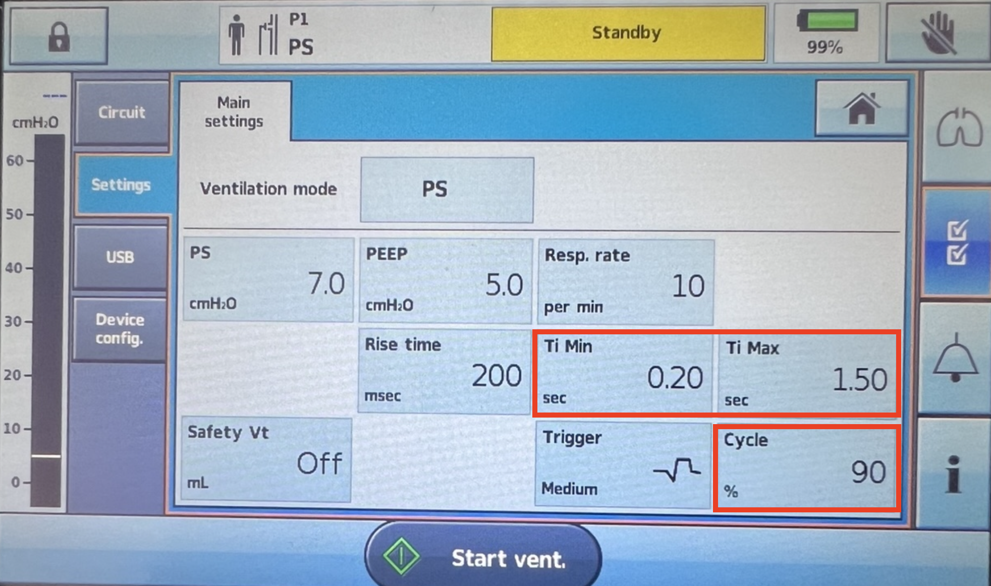
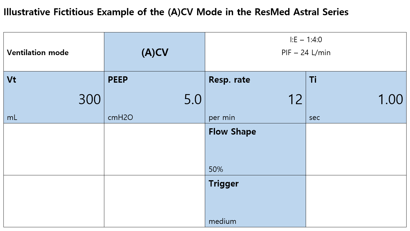
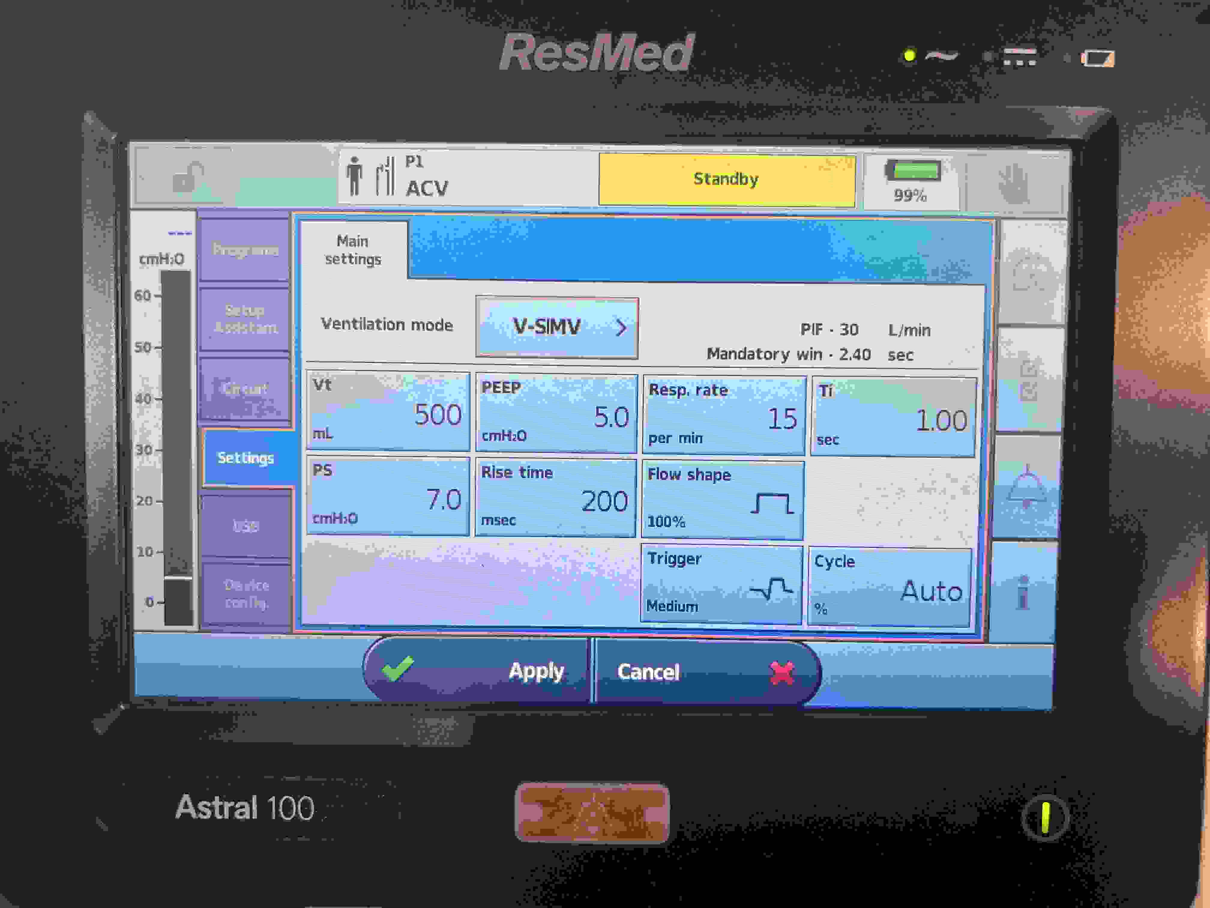
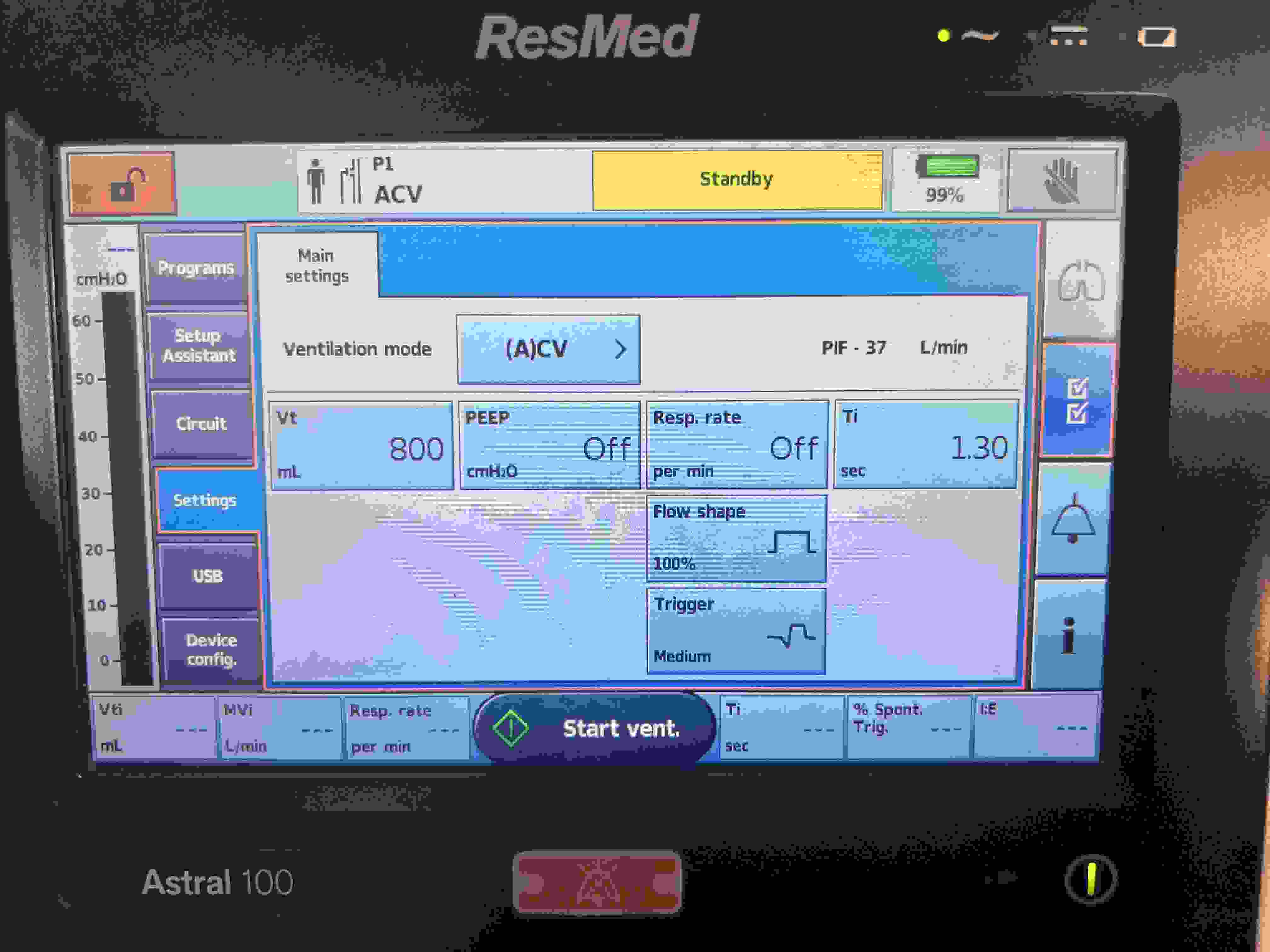
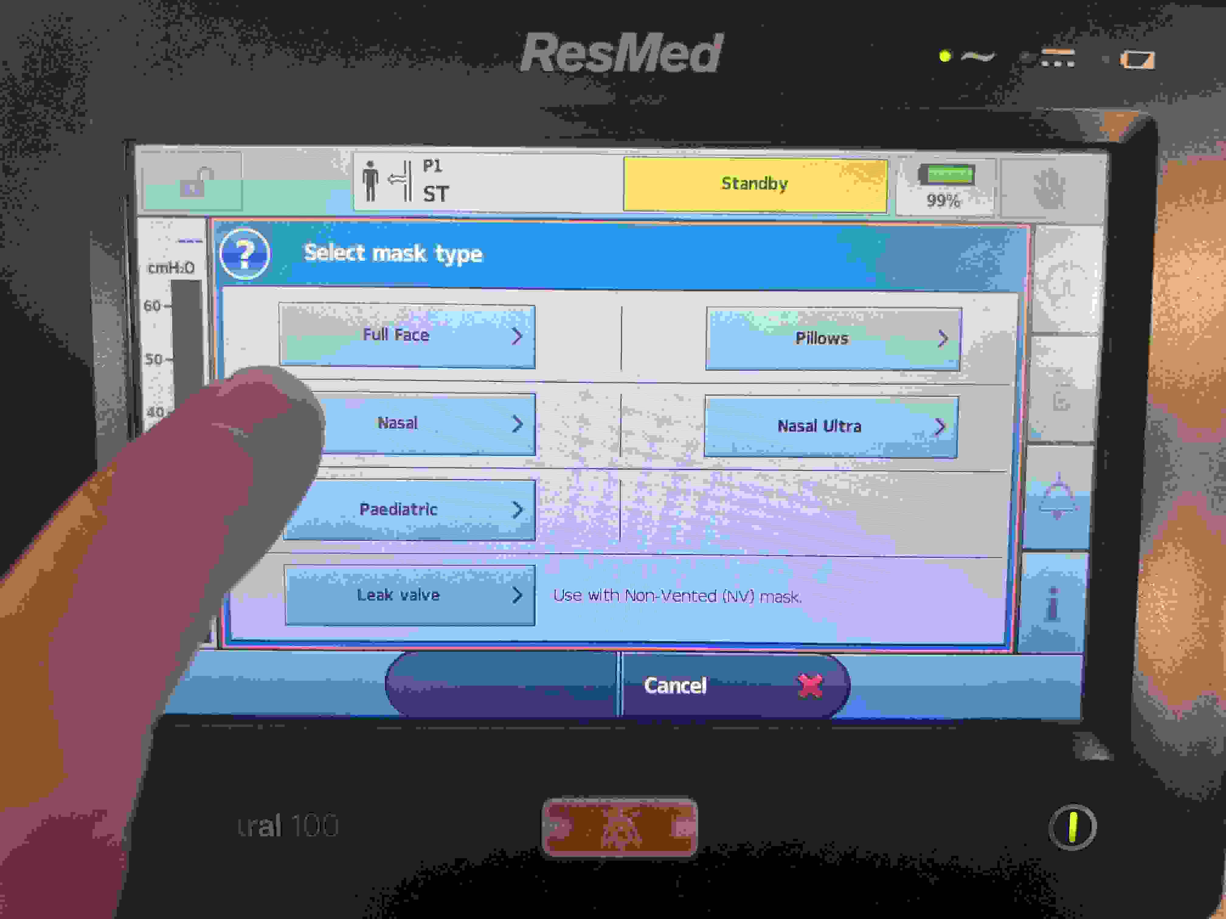
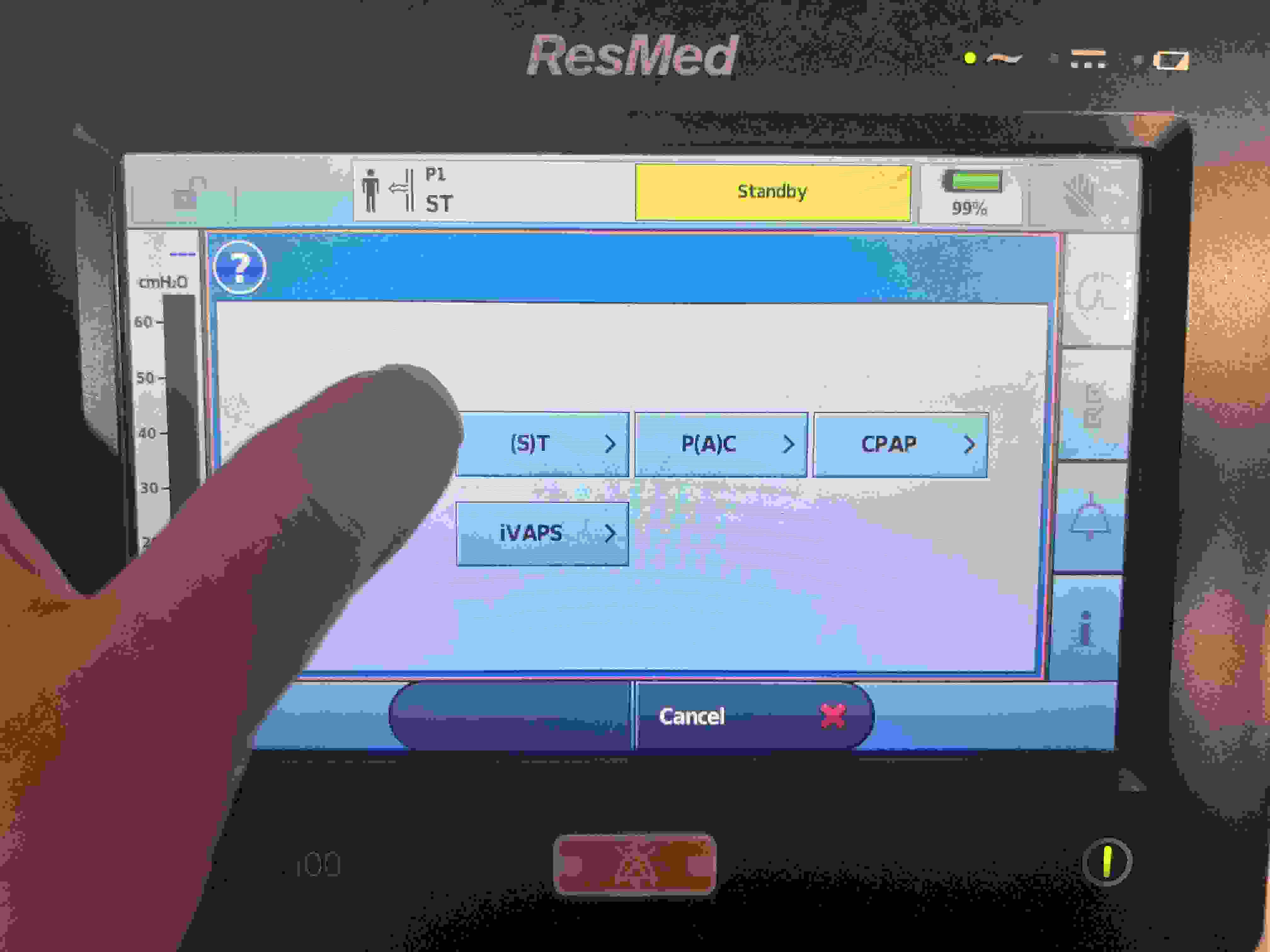
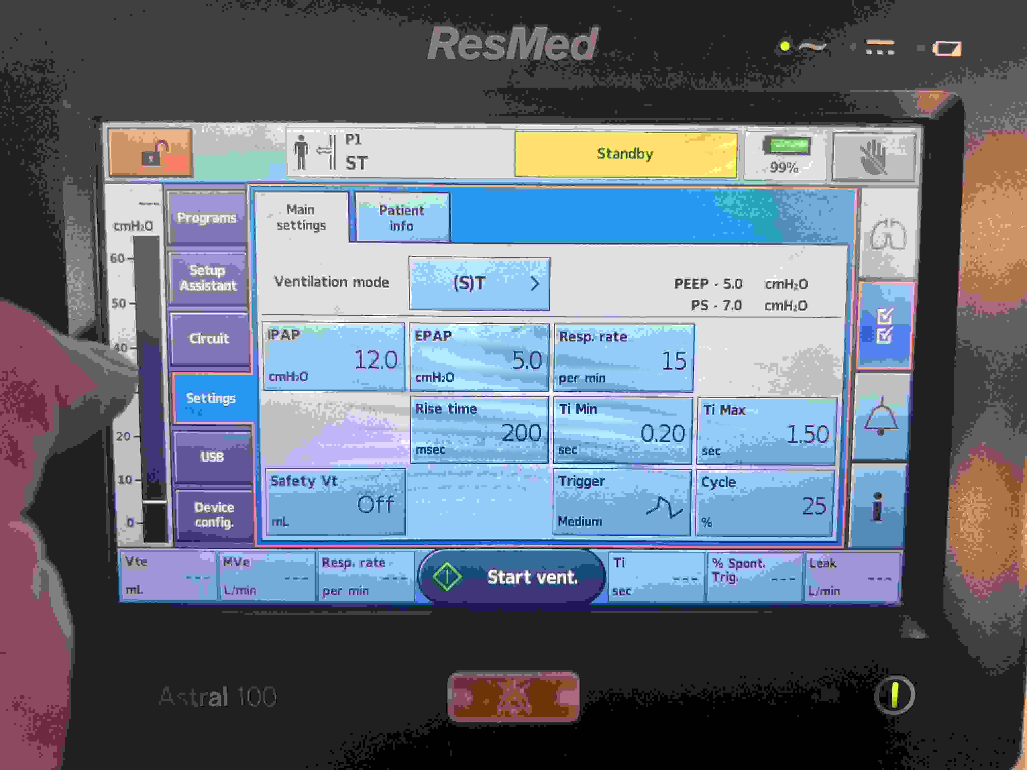
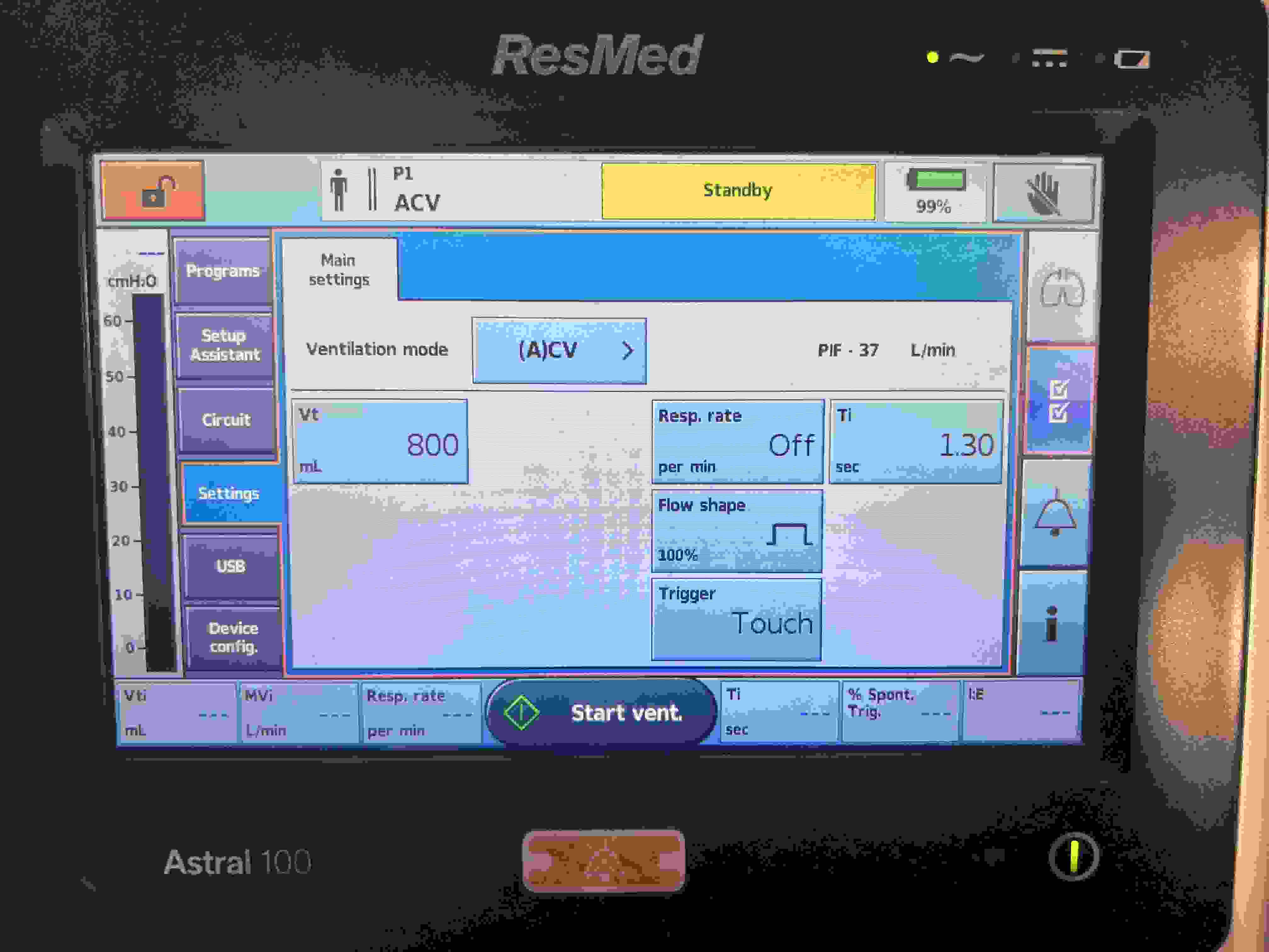
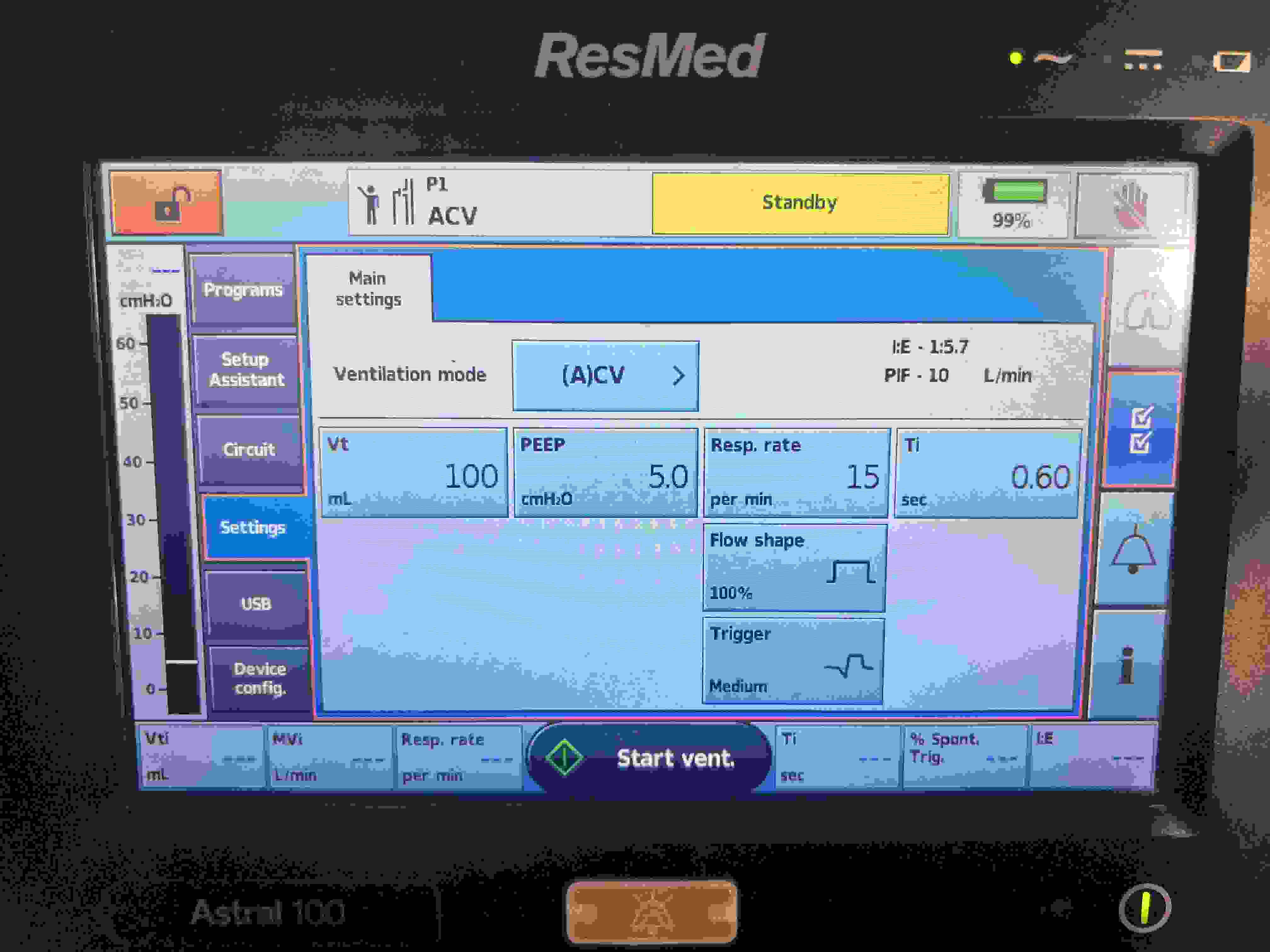
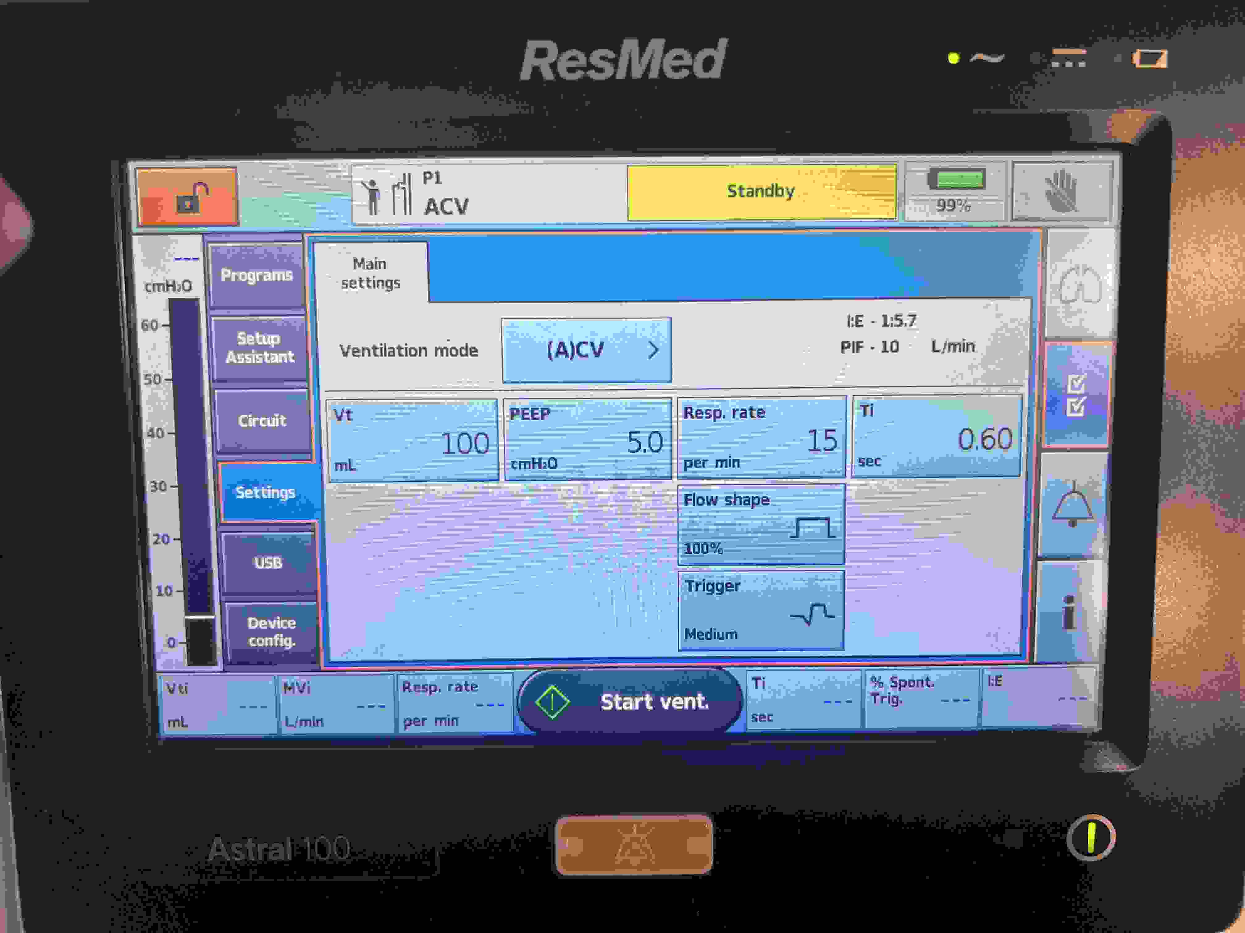
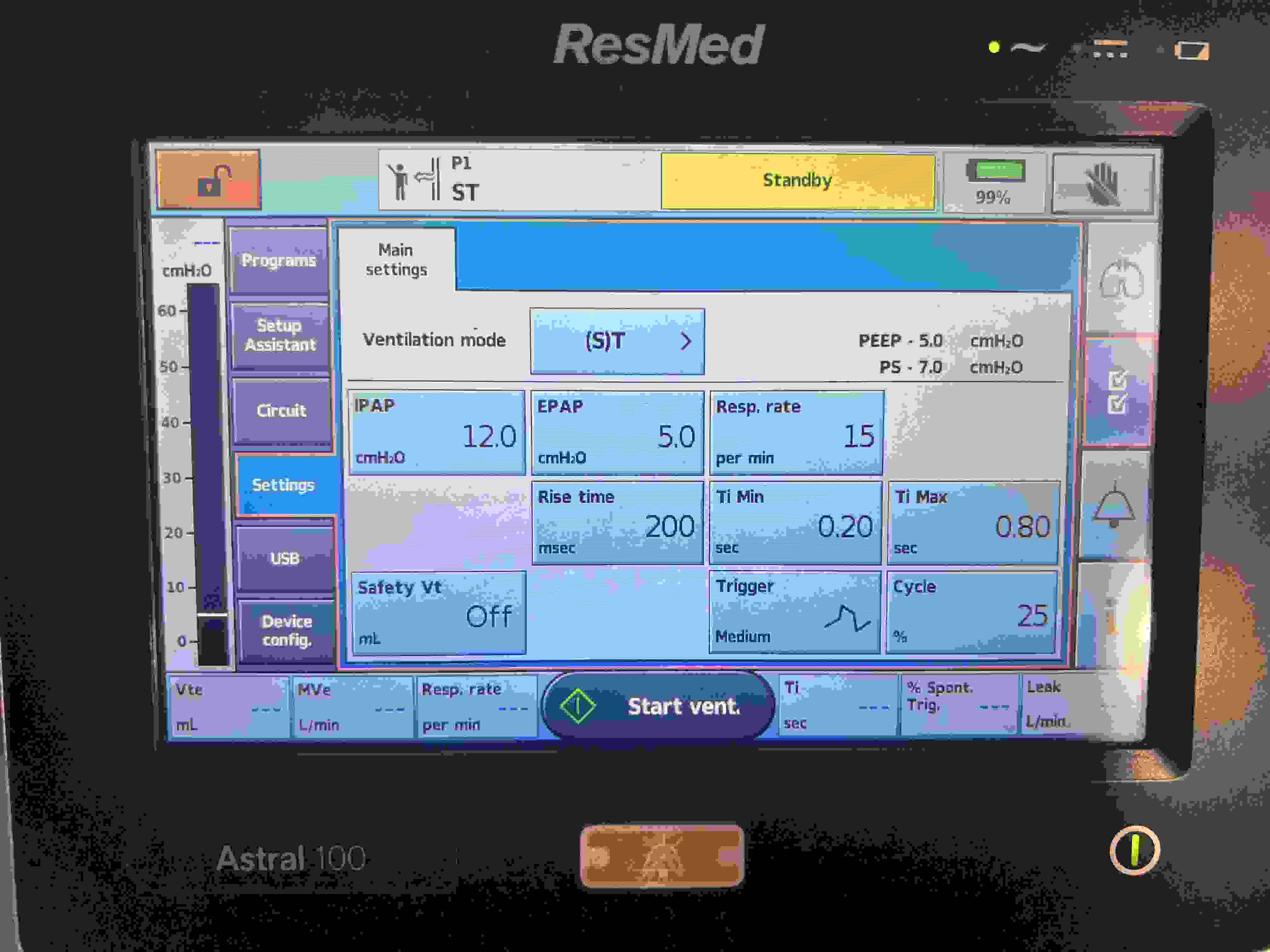
ResMed (A)CV
Vt
PEEP
Resp. rate
Ti (NL: 0.8–1.2 s)
Flow Shape
Safety Vt
Trigger
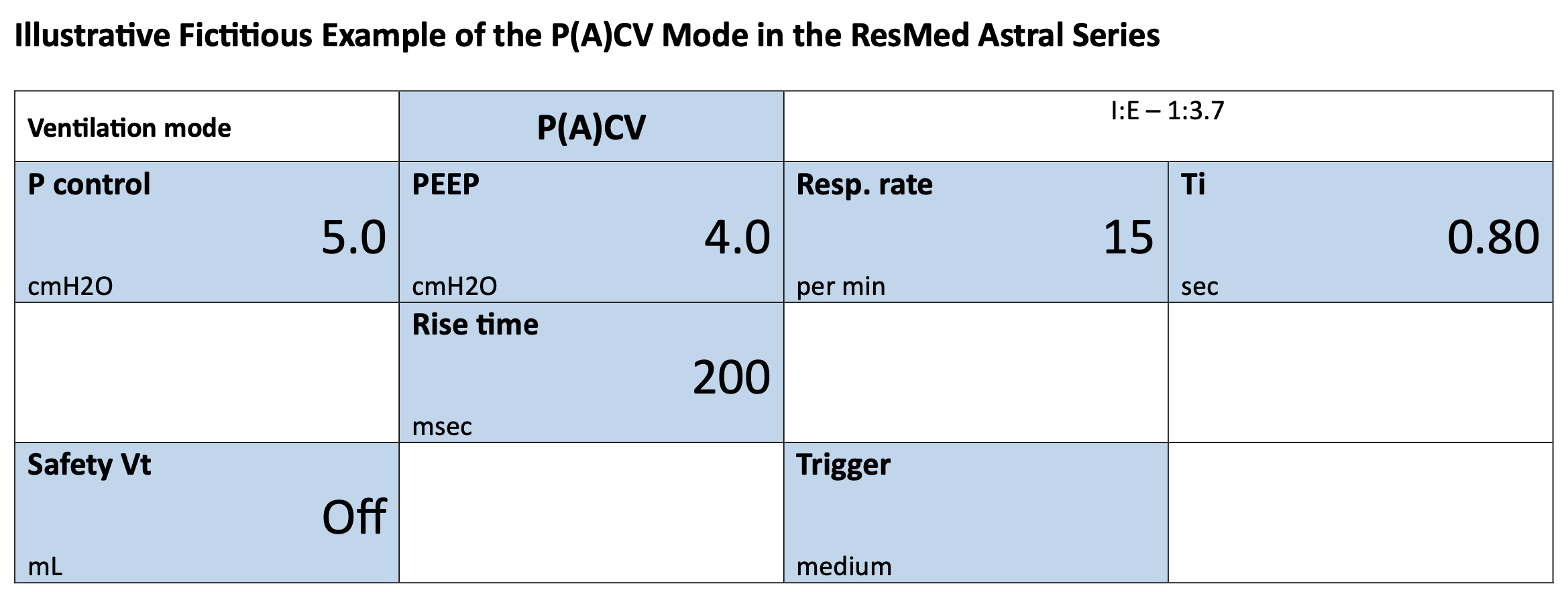
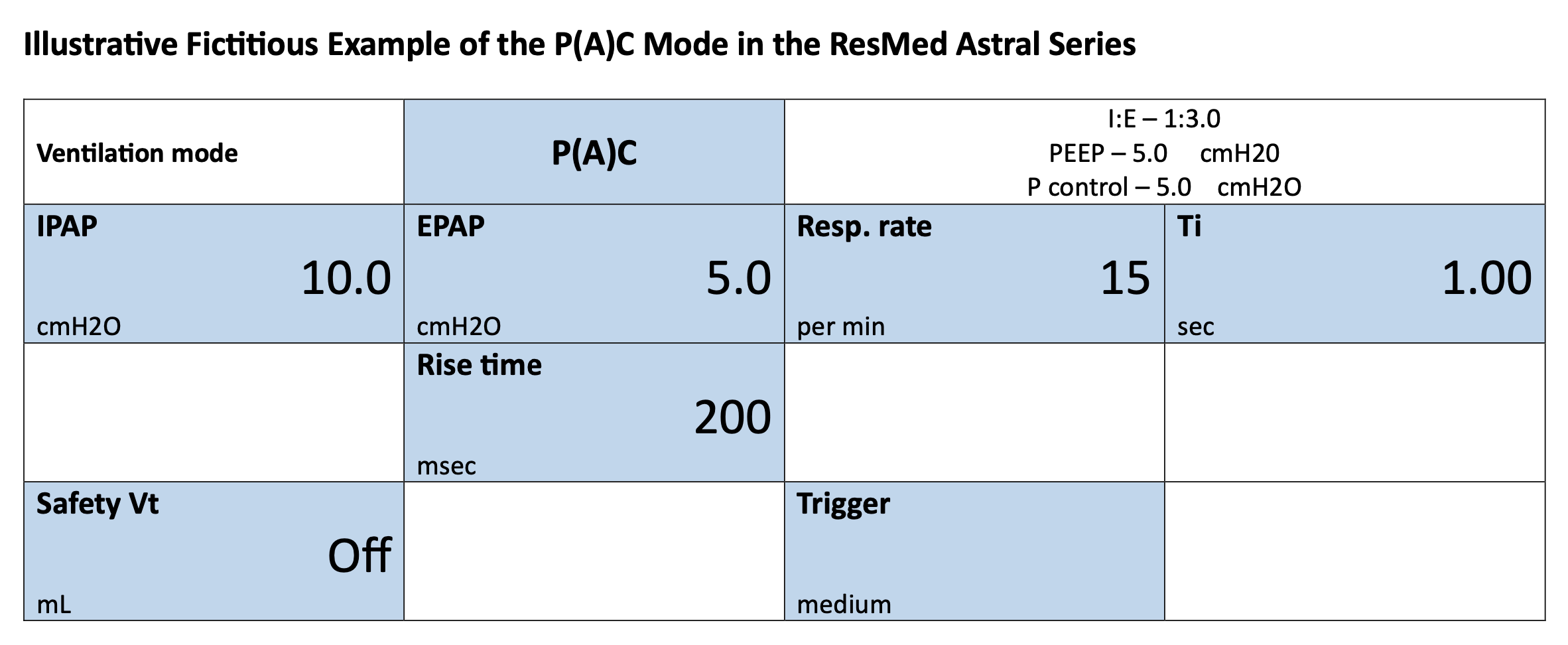
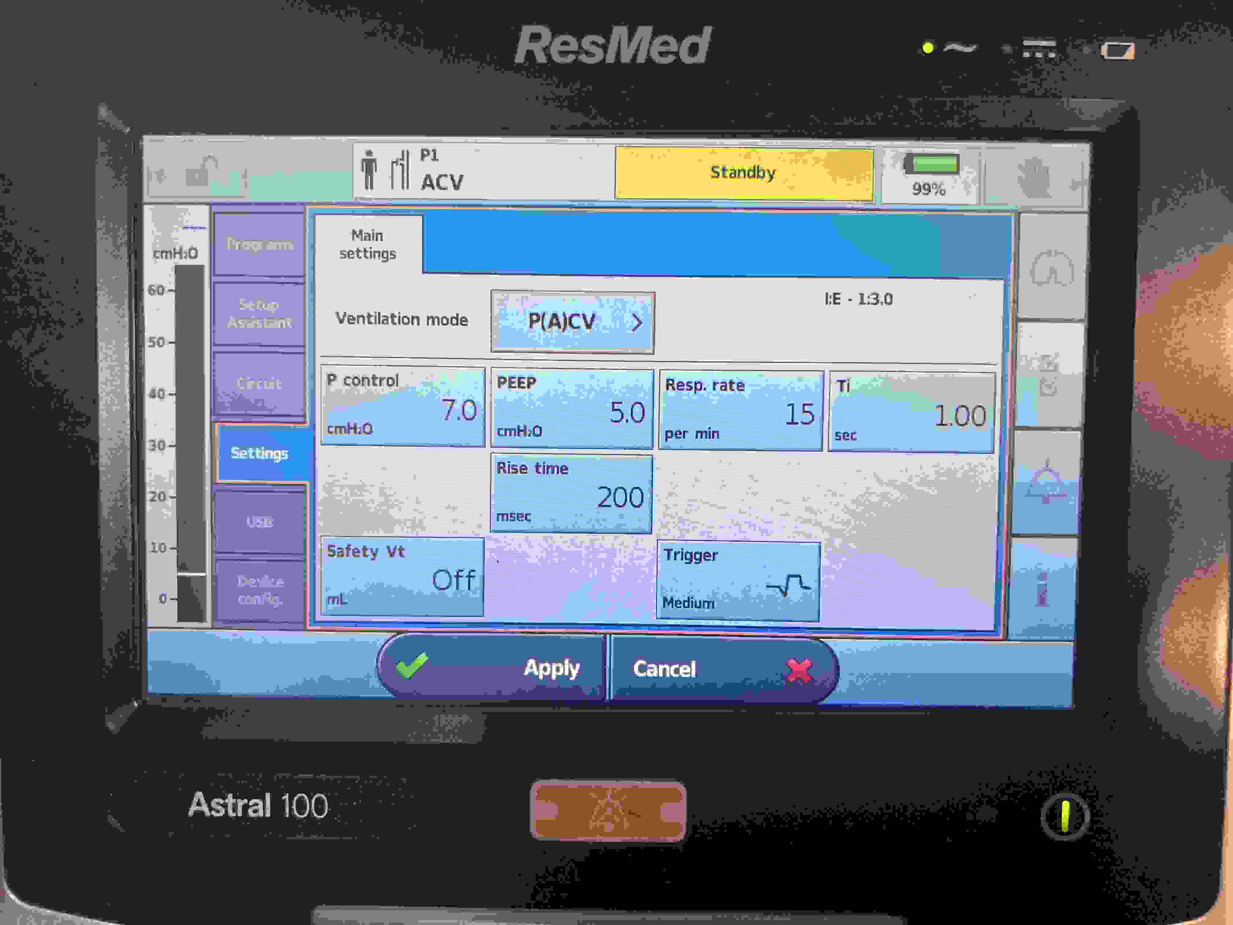
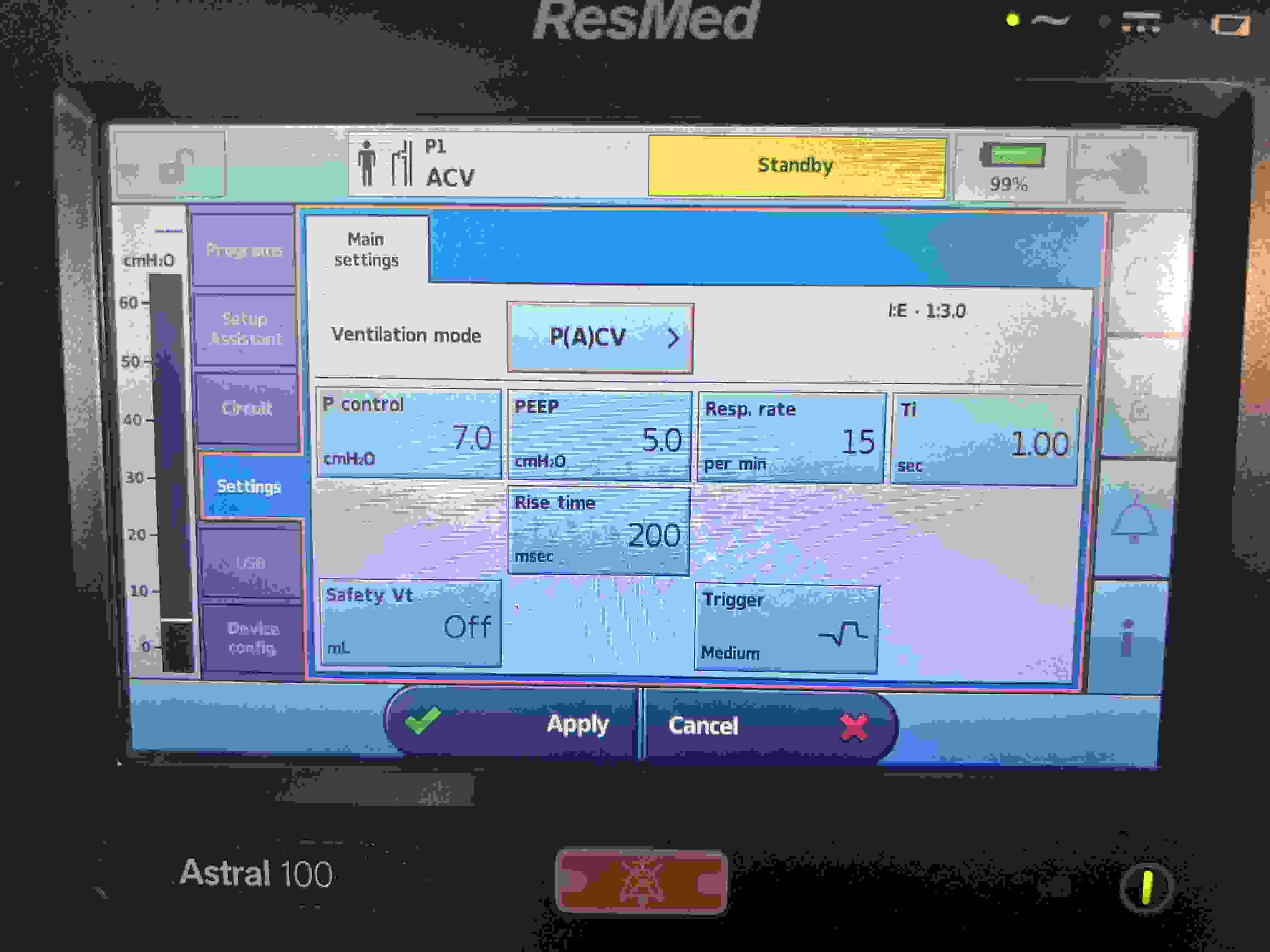
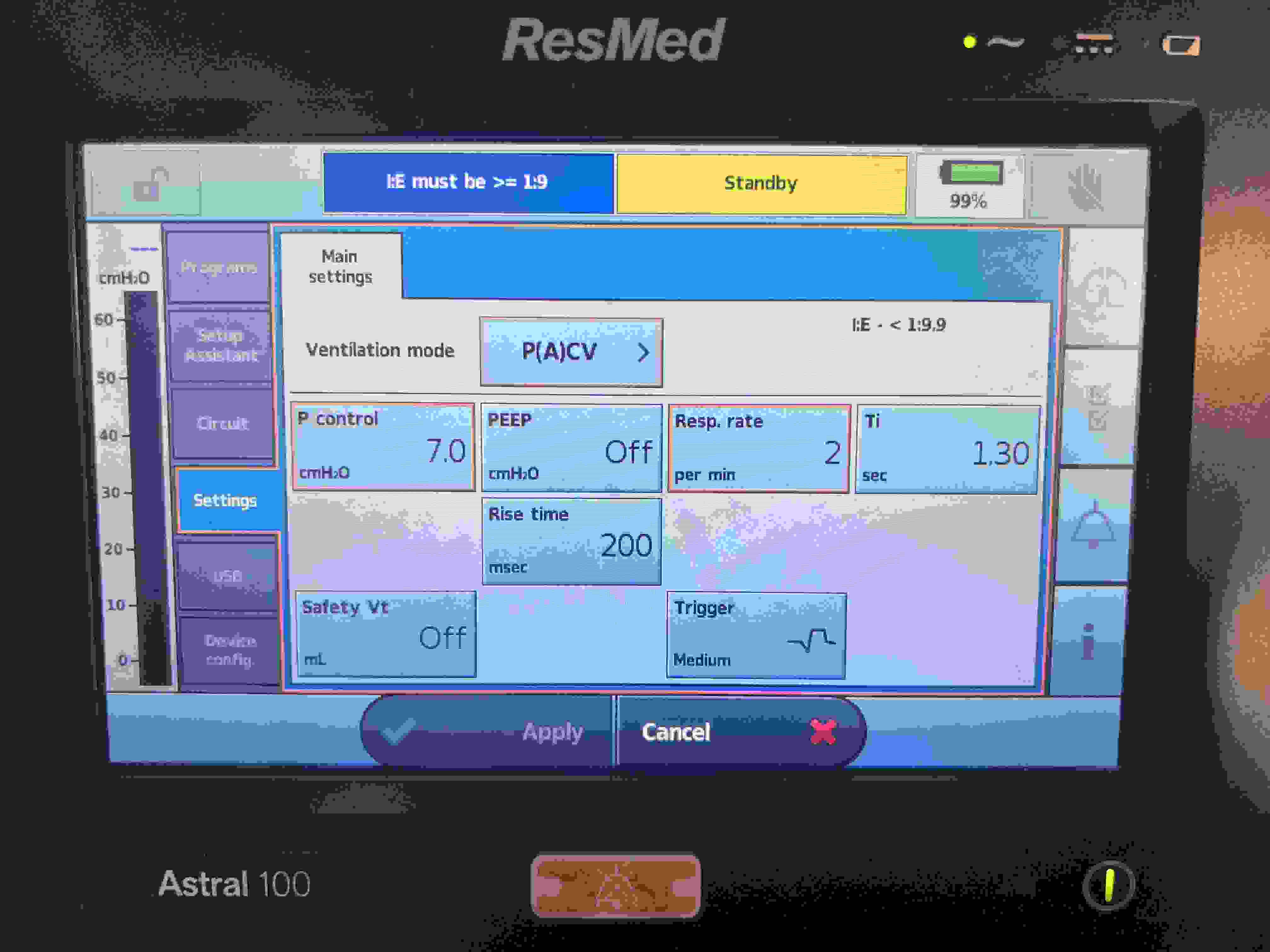
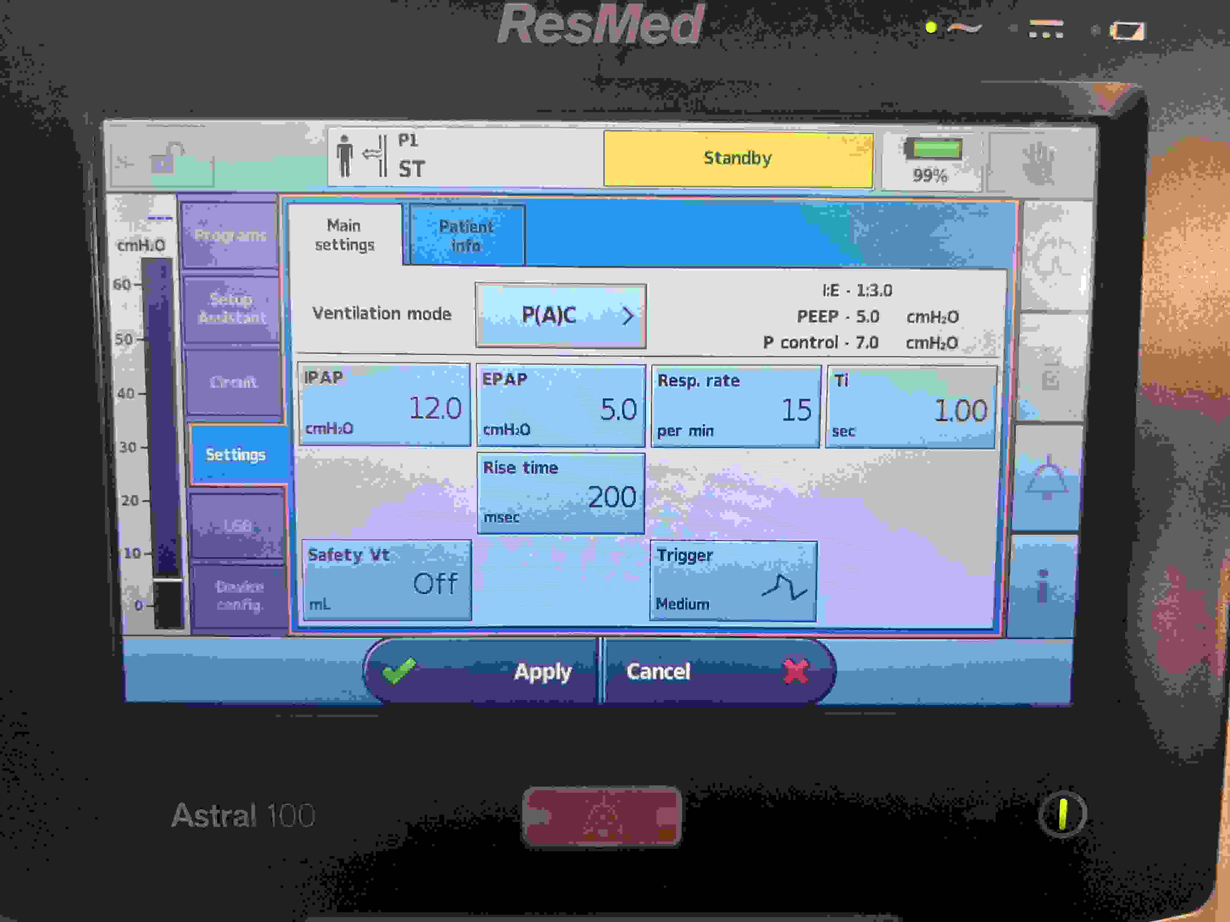
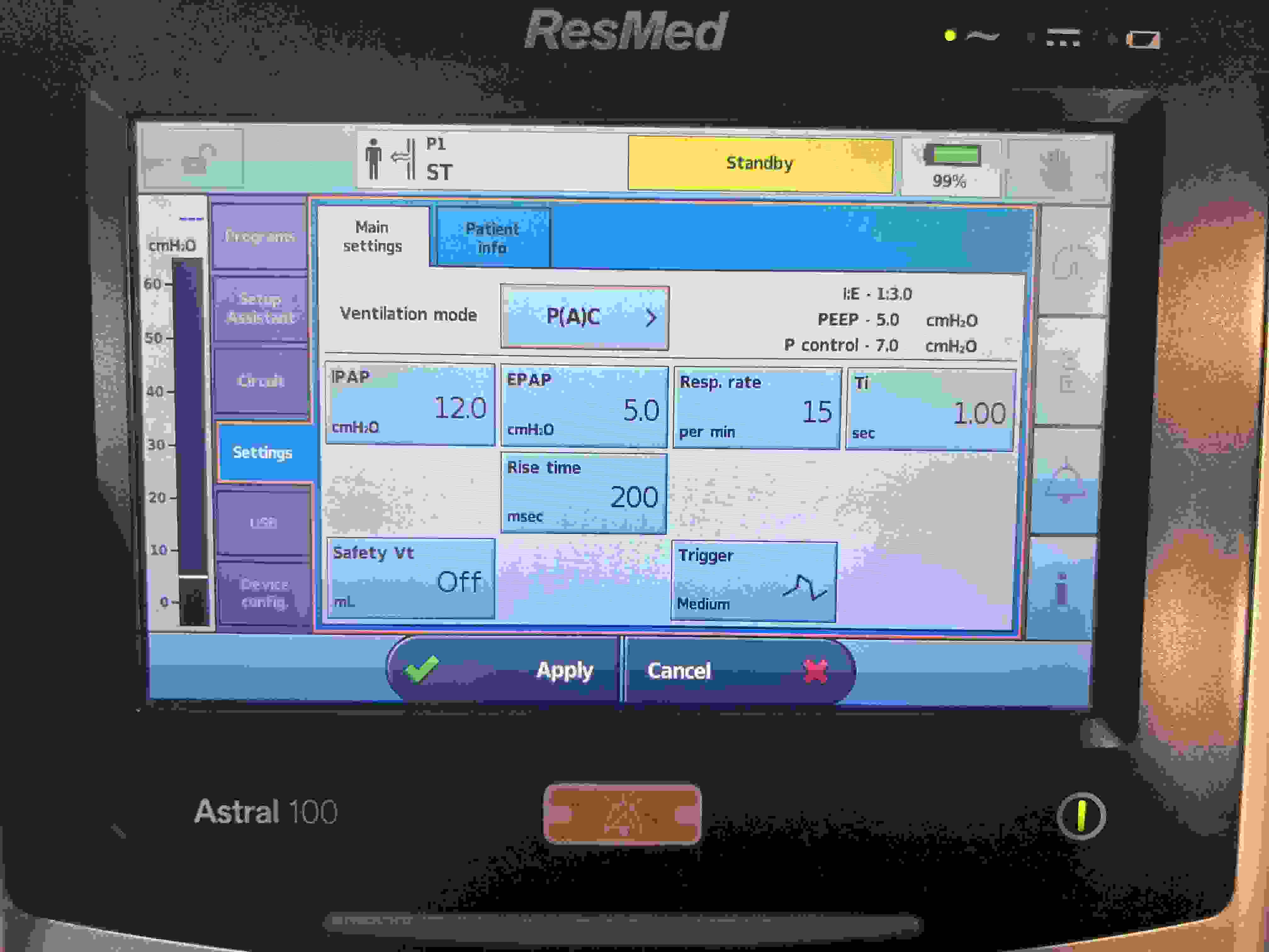
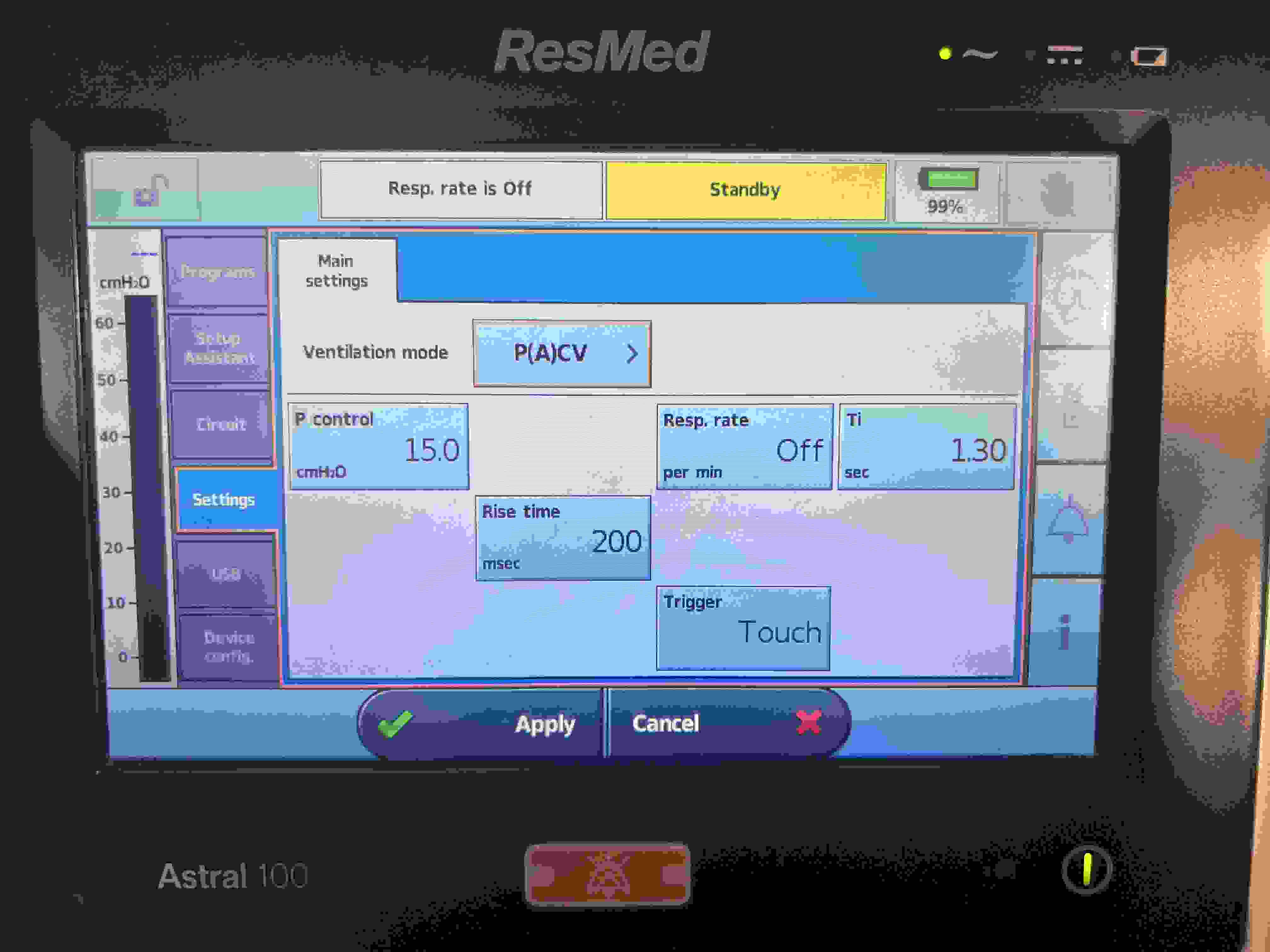
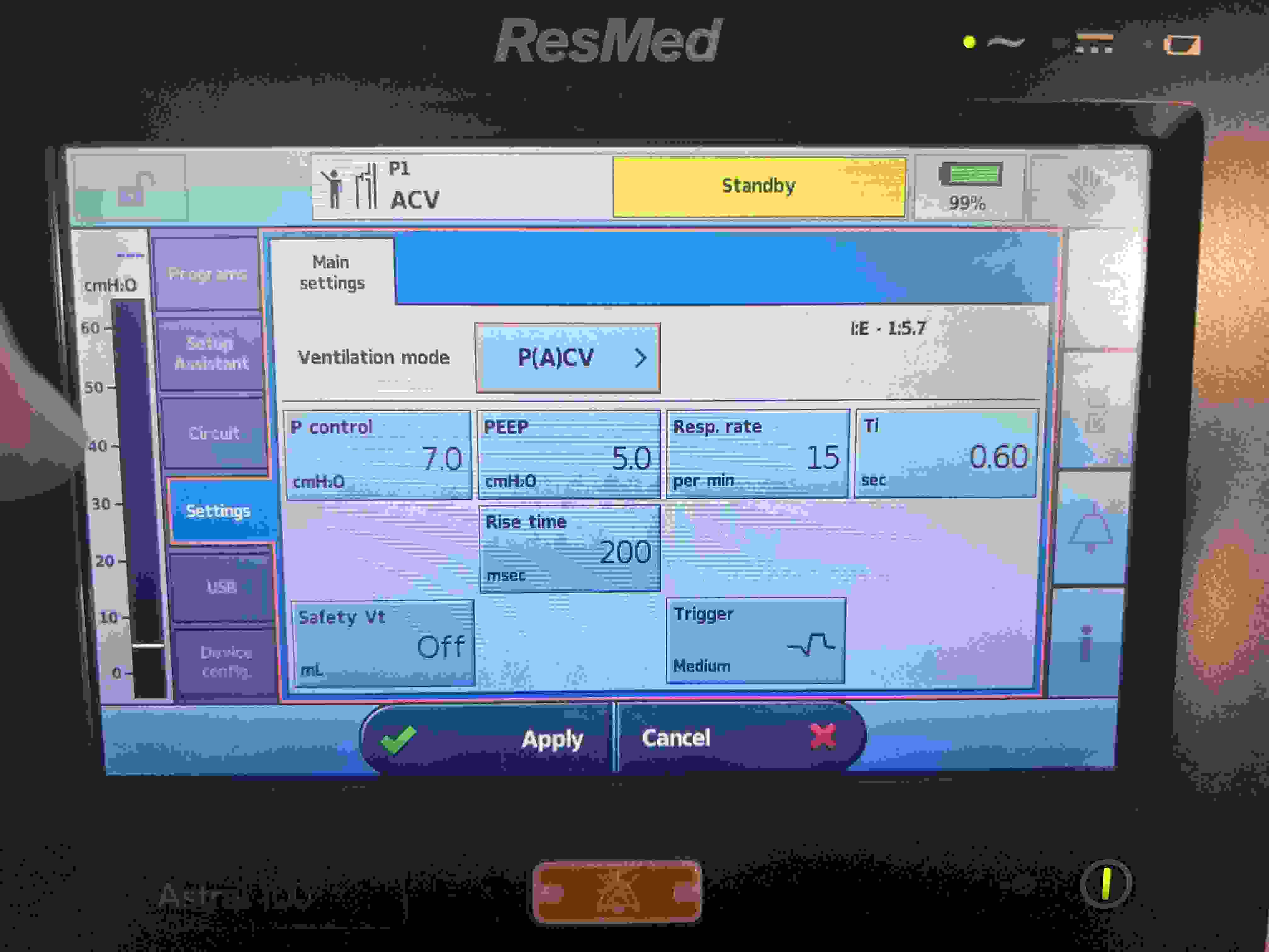
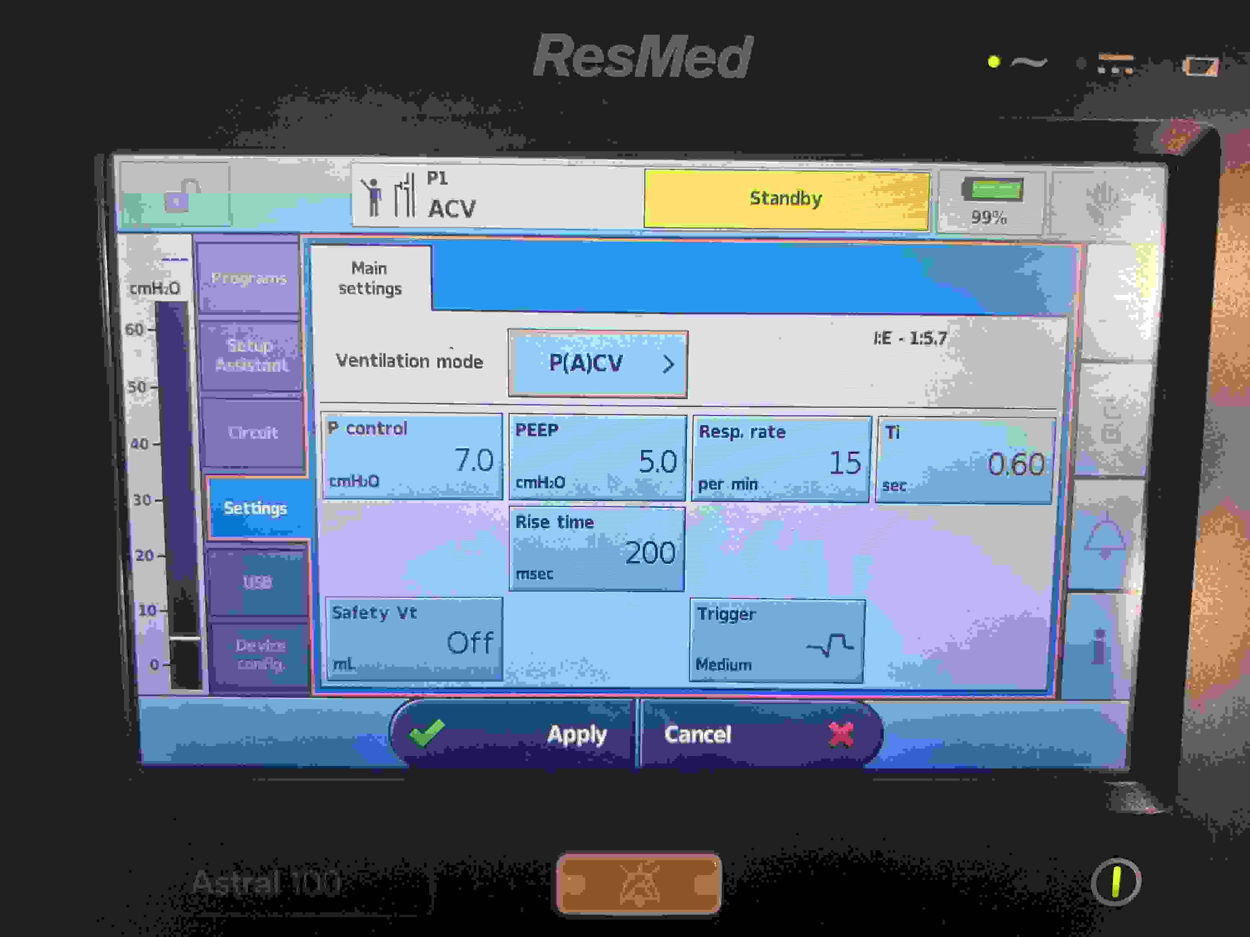
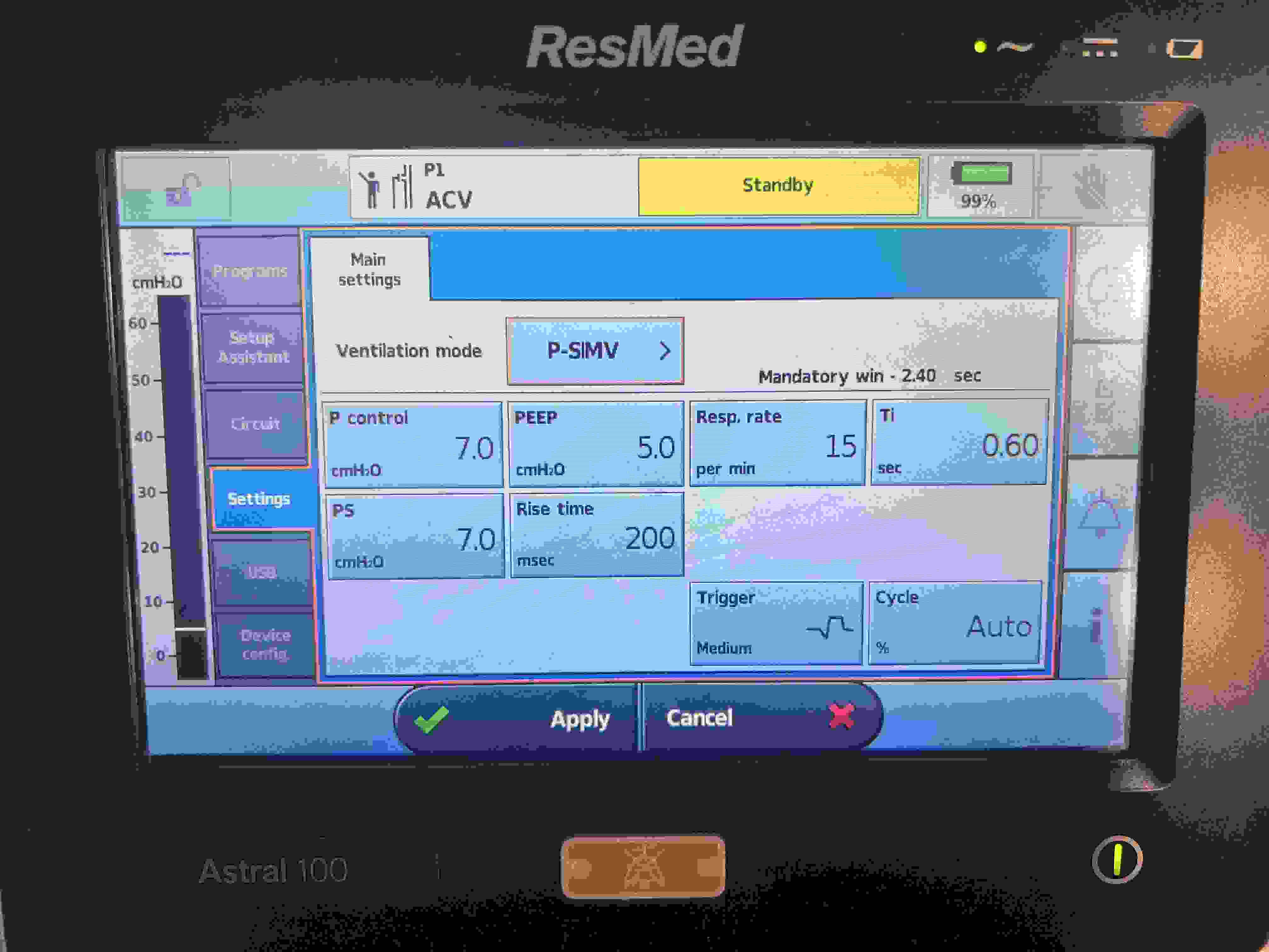
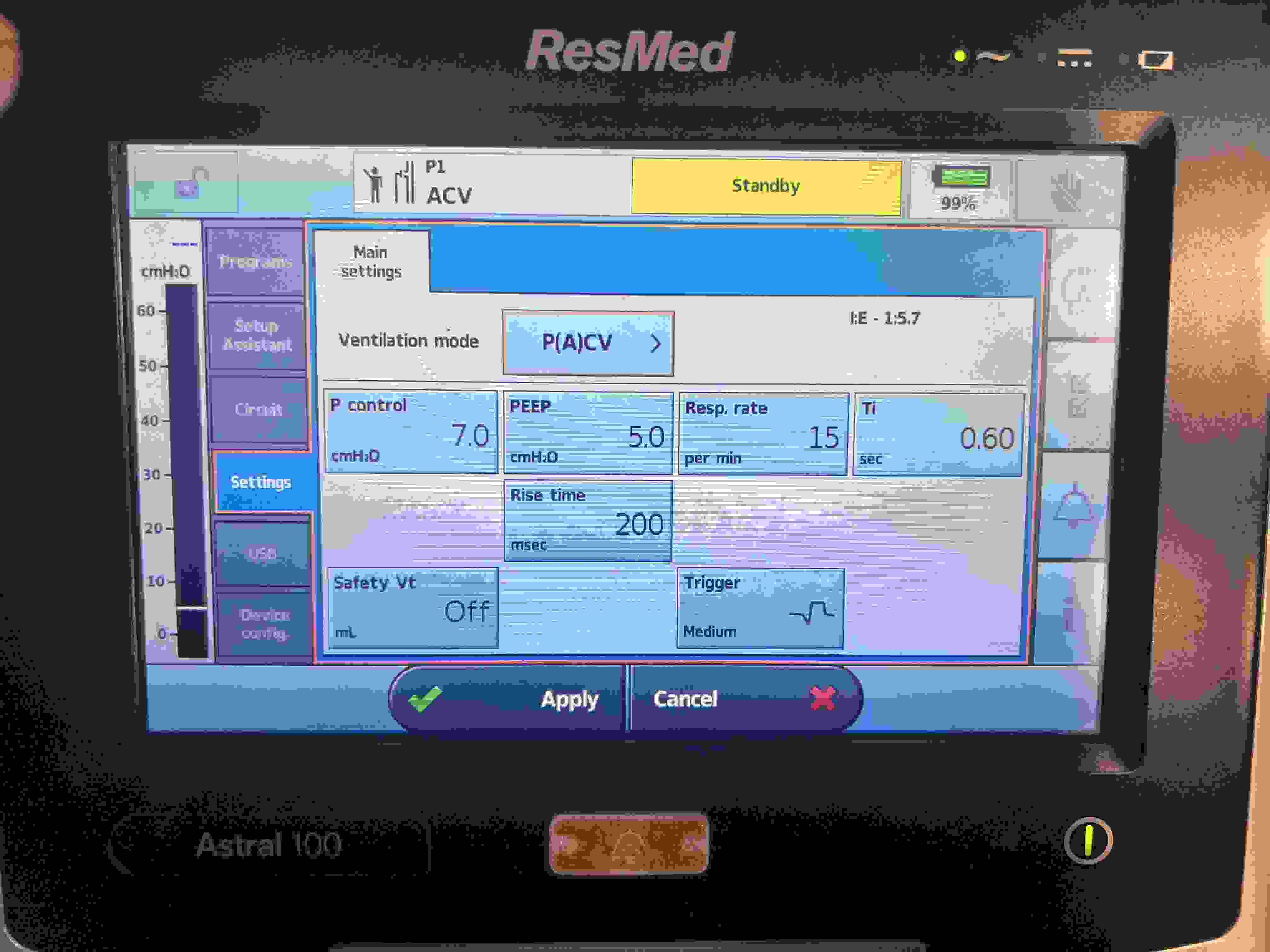
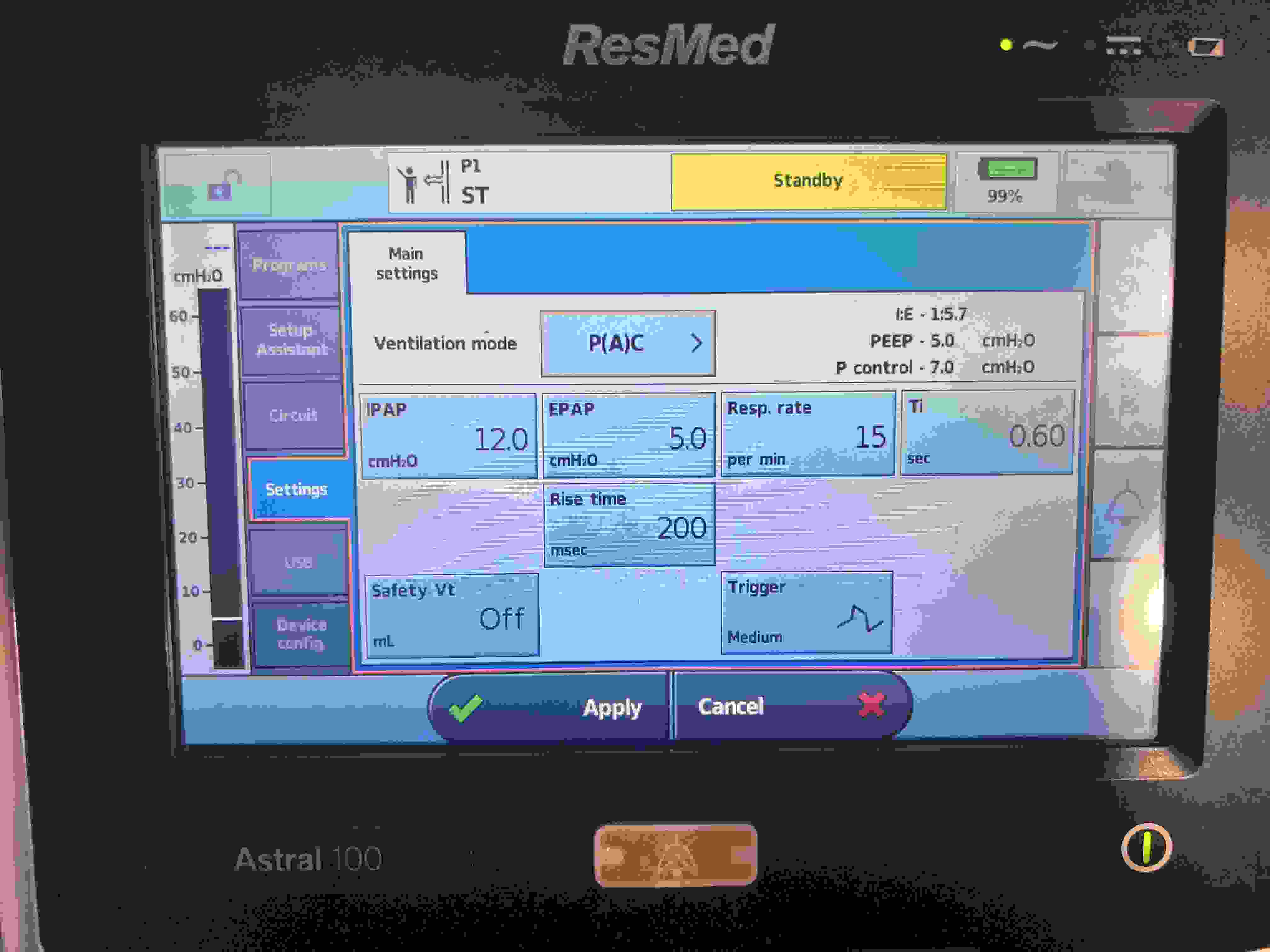
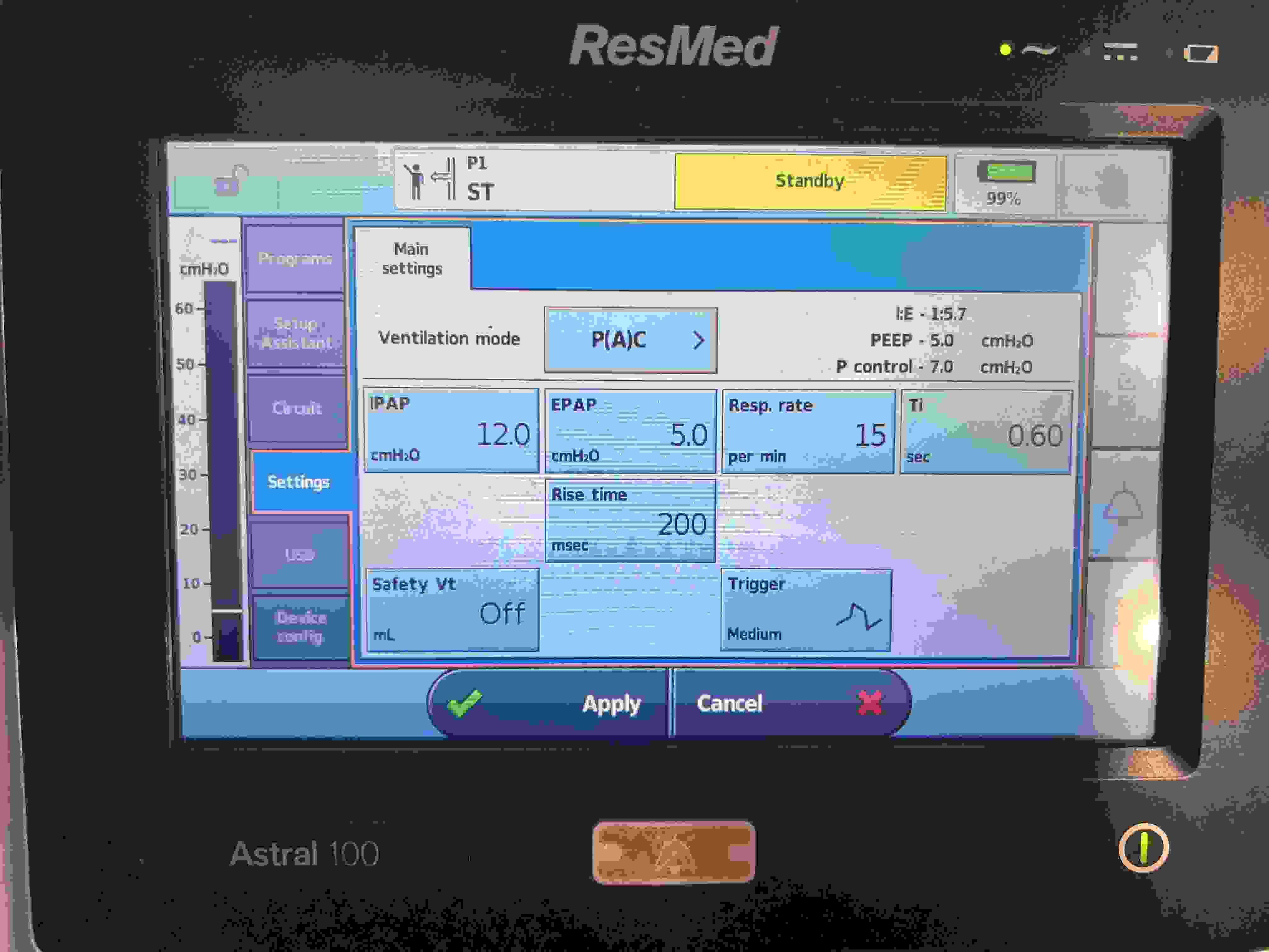
ResMed P(A)CV
P control
PEEP
Resp. rate
Ti (NL: 0.8–1.2 s)
Rise time
Safety Vt
Trigger
Volume Control (VC)
Predicted Body Weight (PBW):N/A kg
Tidal Volume (VT):N/A mL
Minute Ventilation (MV):N/A L/min
Respiratory Rate (RR):N/A breaths/min
Body Surface Area (BSA):N/A m²
VC Ventilator Settings
Mandatory
VT: N/A
RR: N/A
FiO₂: —
PEEP: —
Additional
Inspiratory Flow: —
Flow Pattern: —
Pressure Control (PC)
PBW:N/A kg
VT:N/A mL
Inspiratory Pressure (above PEEP):N/A
MV:N/A L/min
RR:N/A breaths/min
BSA:N/A m²
PC Ventilator Settings
Mandatory
Inspiratory Pressure: N/A
RR: N/A
FiO₂: —
PEEP: —
Additional
Inspiratory Time: —
Ramp Slope: —
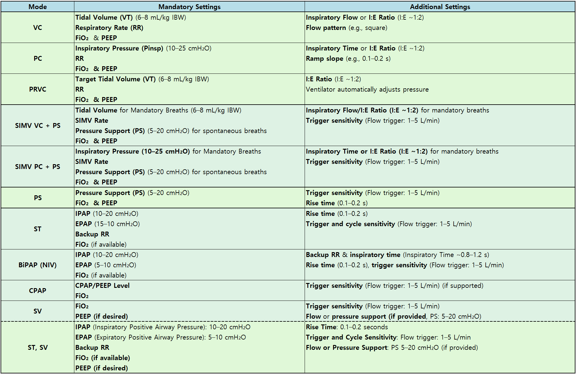
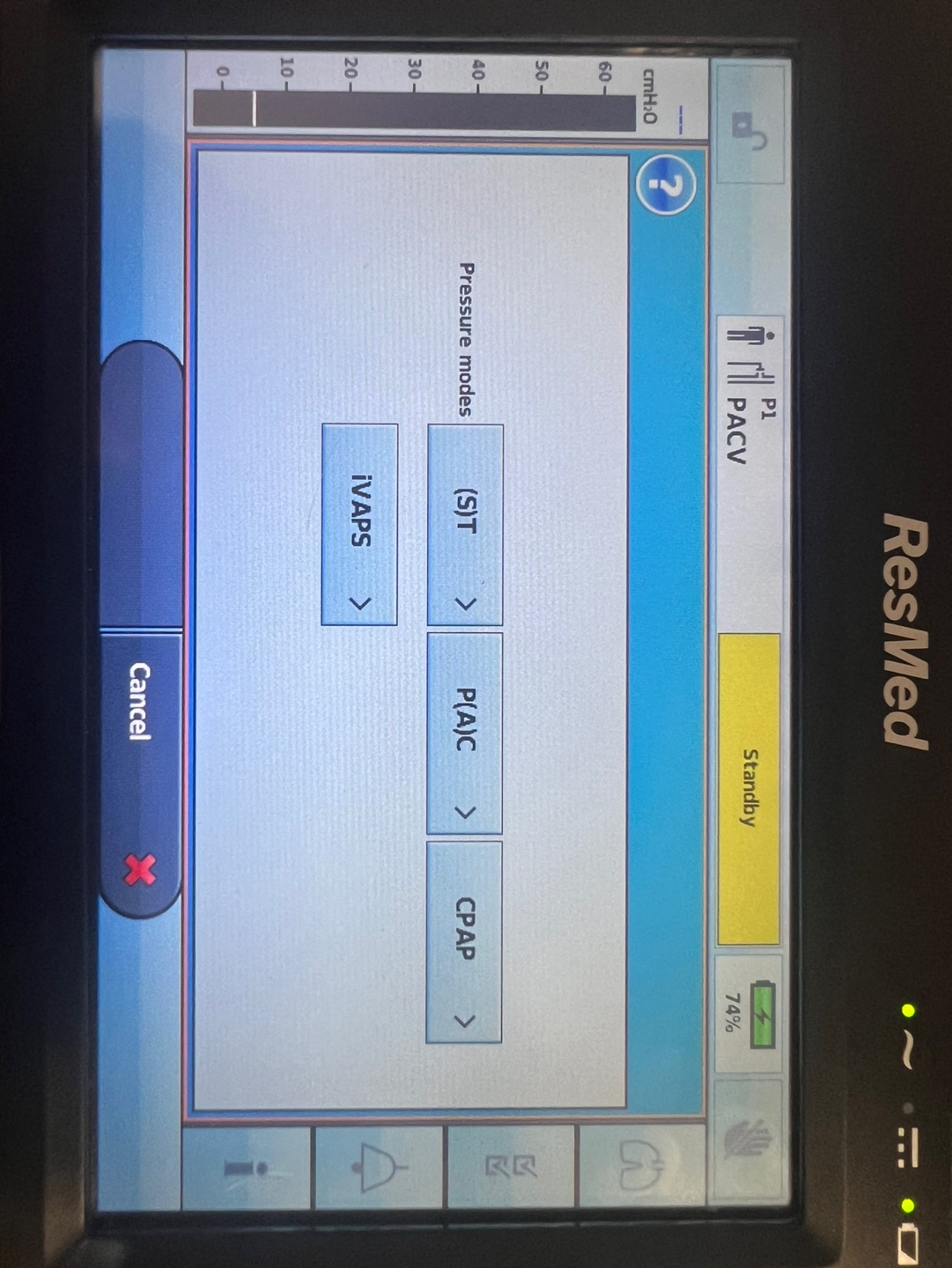
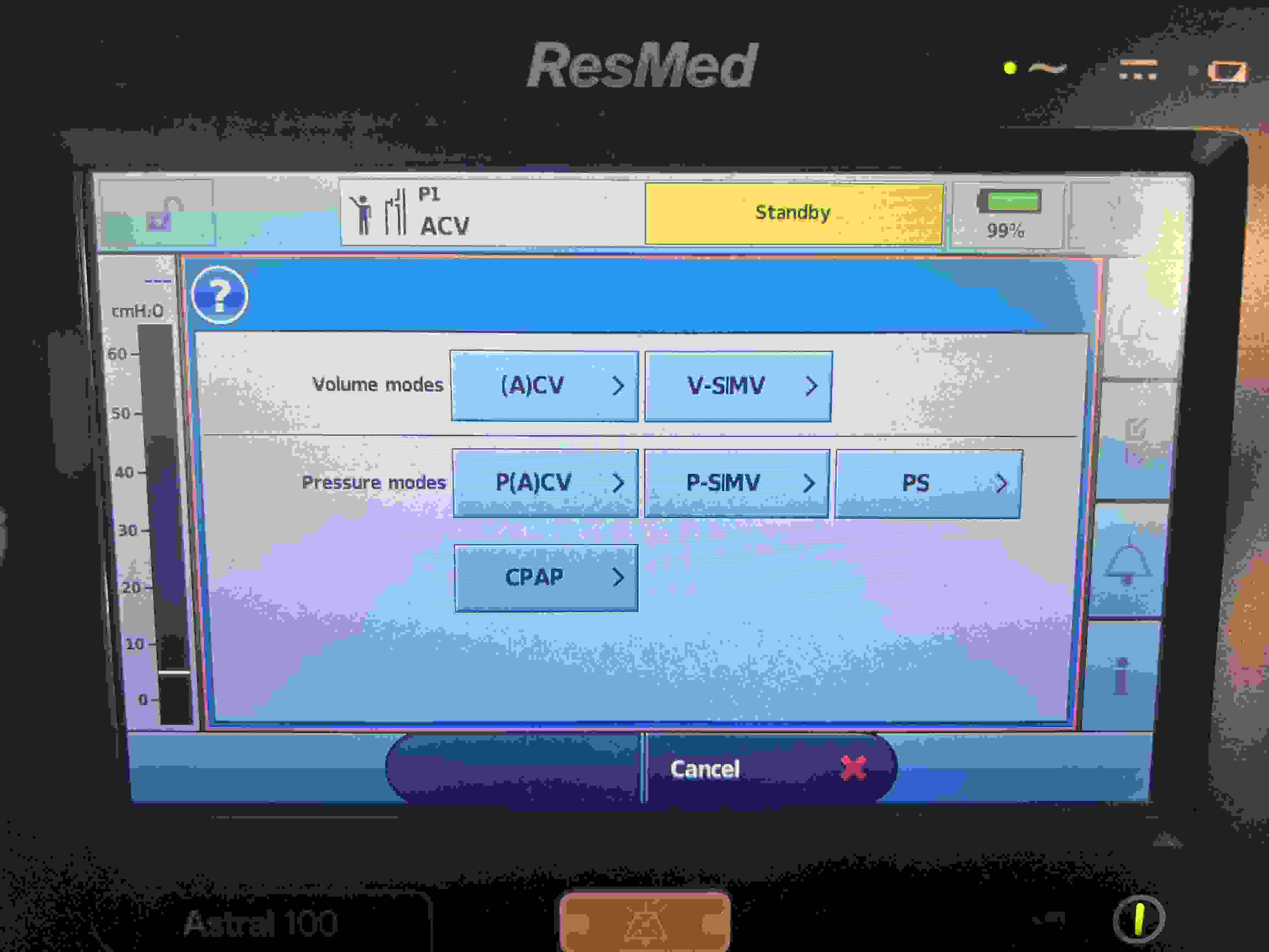
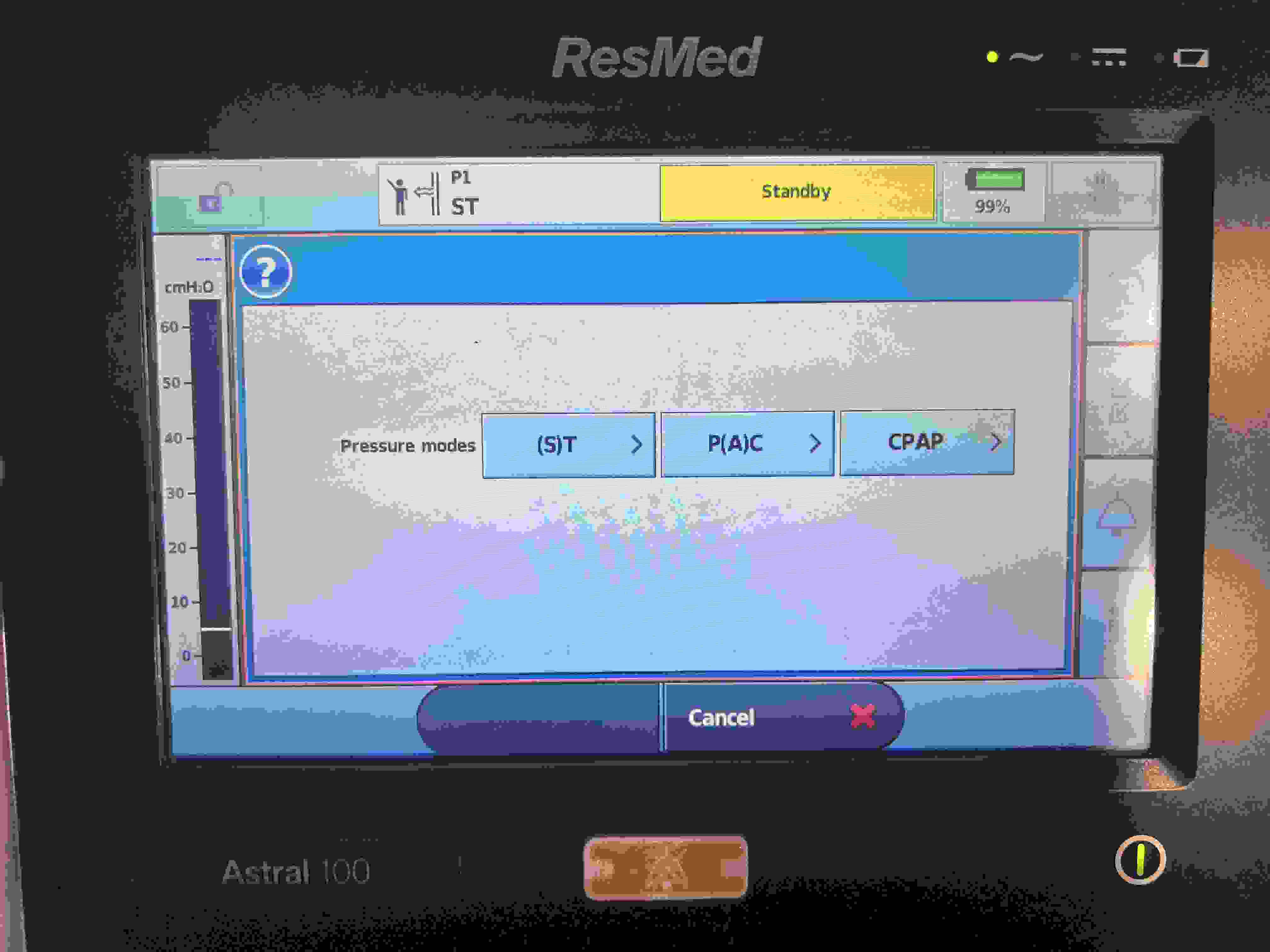
Ventilator Modes and Required Variable Settings
The table below provides a structured overview of common ventilator modes, arranged from those relying primarily on machine-driven parameters to those granting greater patient autonomy. Each mode lists the primary control variable, mandatory settings (with typical ranges where applicable), and additional adjustable parameters. The ranges and values are considered guidelines and may vary depending on clinical judgment and individual patient needs.
Mode
Primary Control Variable
Mandatory Settings
Additional Settings
VC (Volume Control)
Volume
Tidal Volume (VT) (6–8 mL/kg IBW)
Respiratory Rate (RR)
FiO₂
PEEP
Inspiratory Flow or I:E Ratio (I:E ~1:2)
Flow pattern (e.g., square)
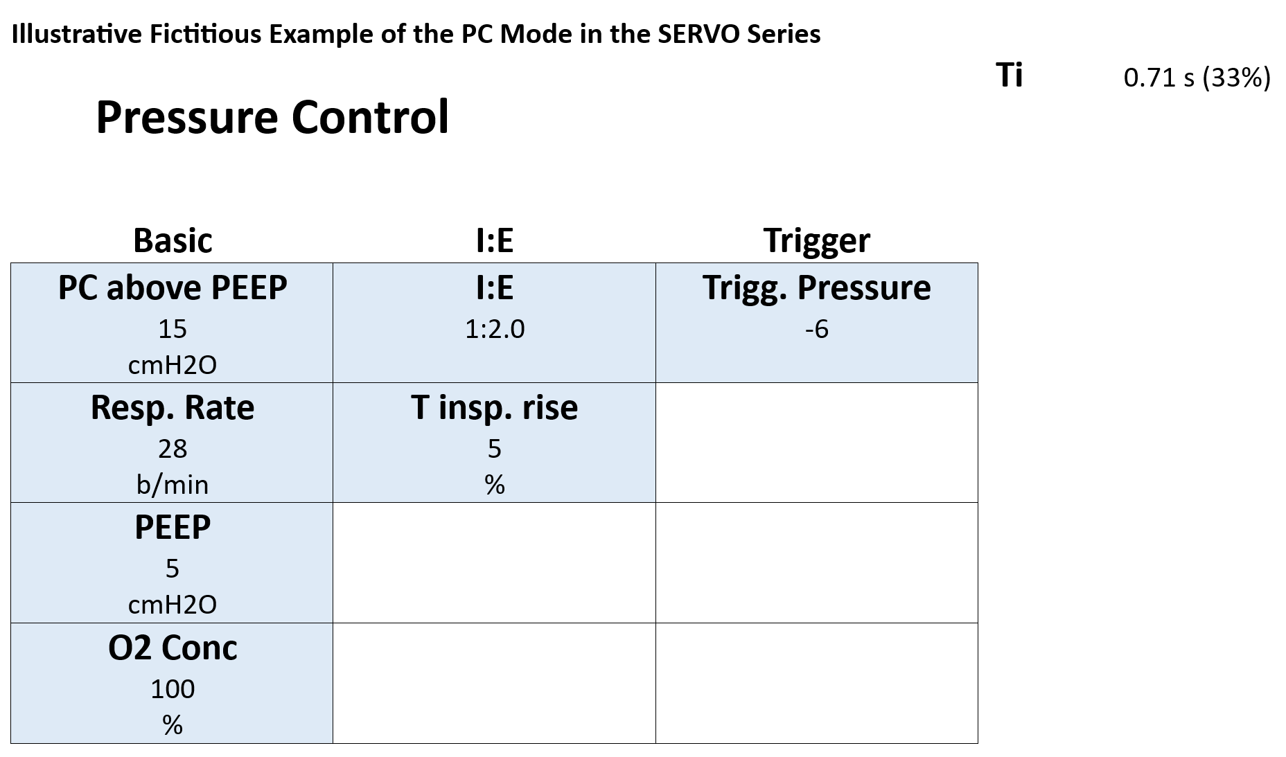
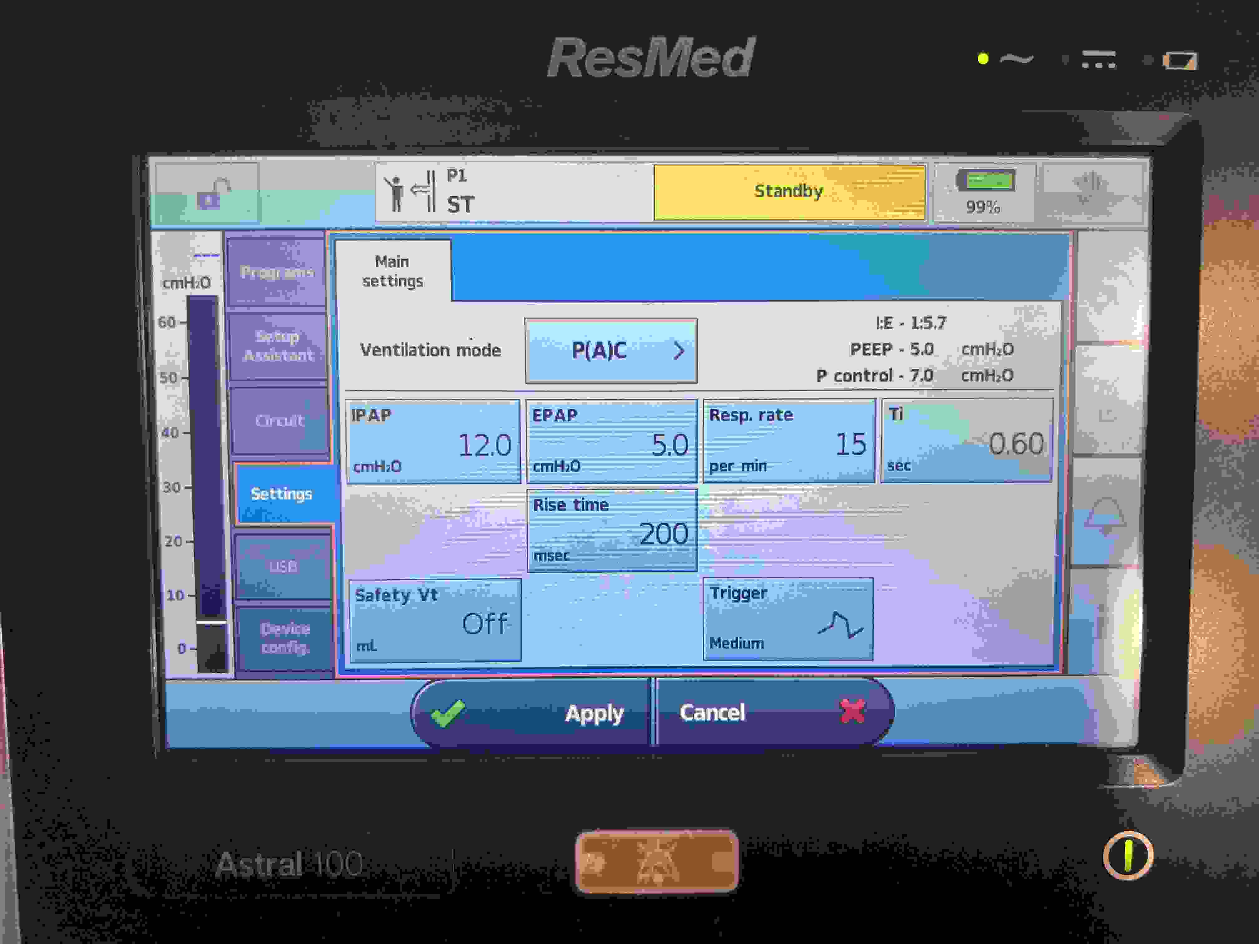
PC (Pressure Control)
Pressure
Set Inspiratory Pressure (Pinsp) (≈10–25 cmH₂O)
RR
FiO₂
PEEP
Inspiratory Time or I:E Ratio (I:E ~1:2)
Ramp slope (e.g., 0.1–0.2 s)
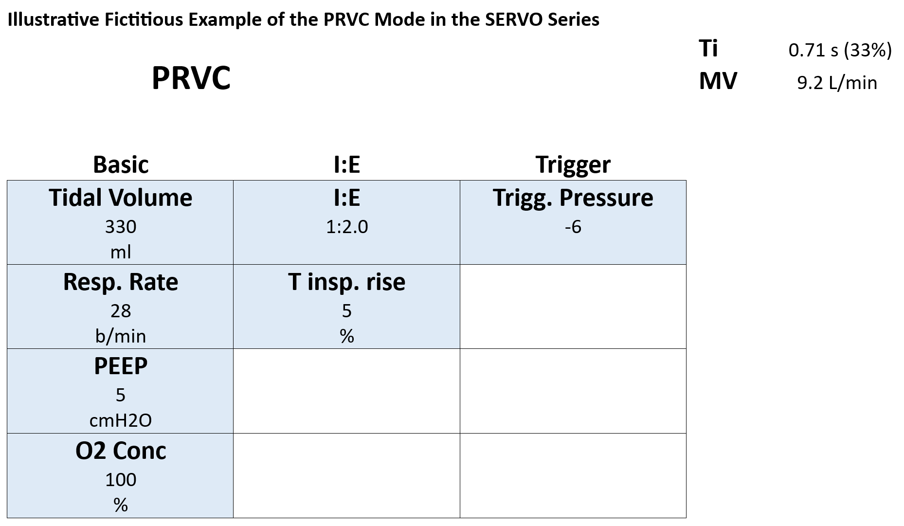
PRVC (Pressure Regulated Volume Control)
Volume-targeted, Pressure-limited
Target Tidal Volume (VT) (6–8 mL/kg IBW)
RR
FiO₂
PEEP
I:E Ratio (I:E ~1:2)
Ventilator automatically adjusts pressure
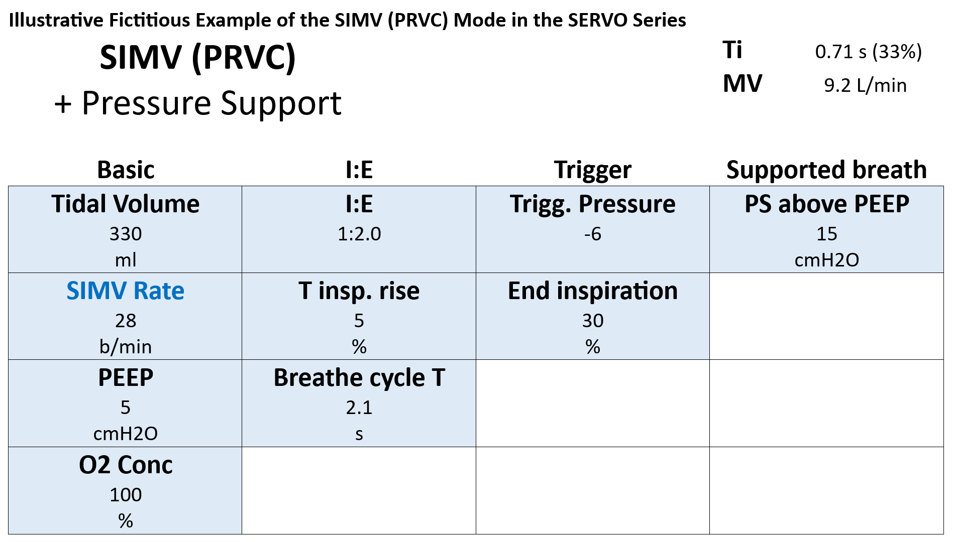
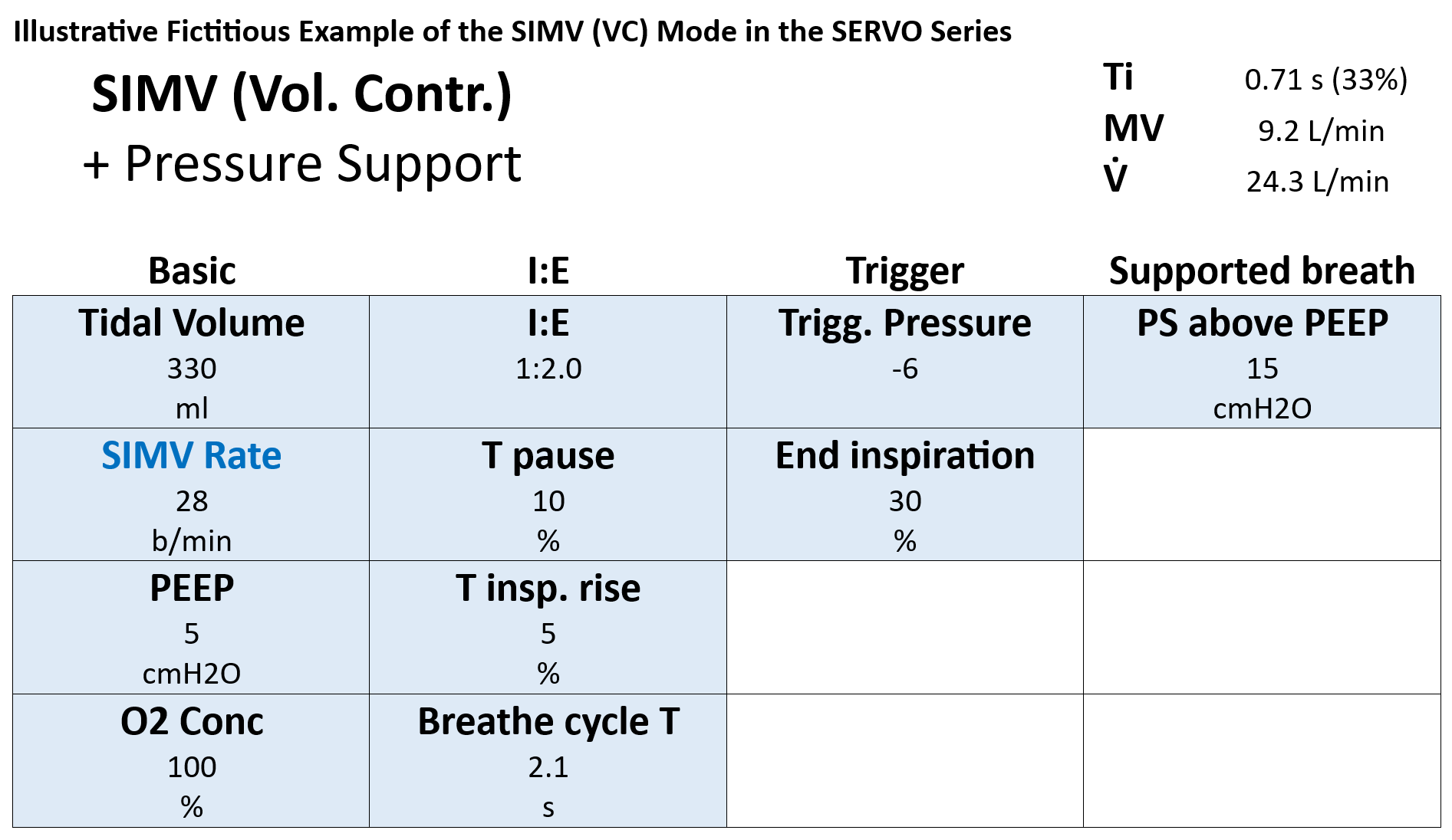
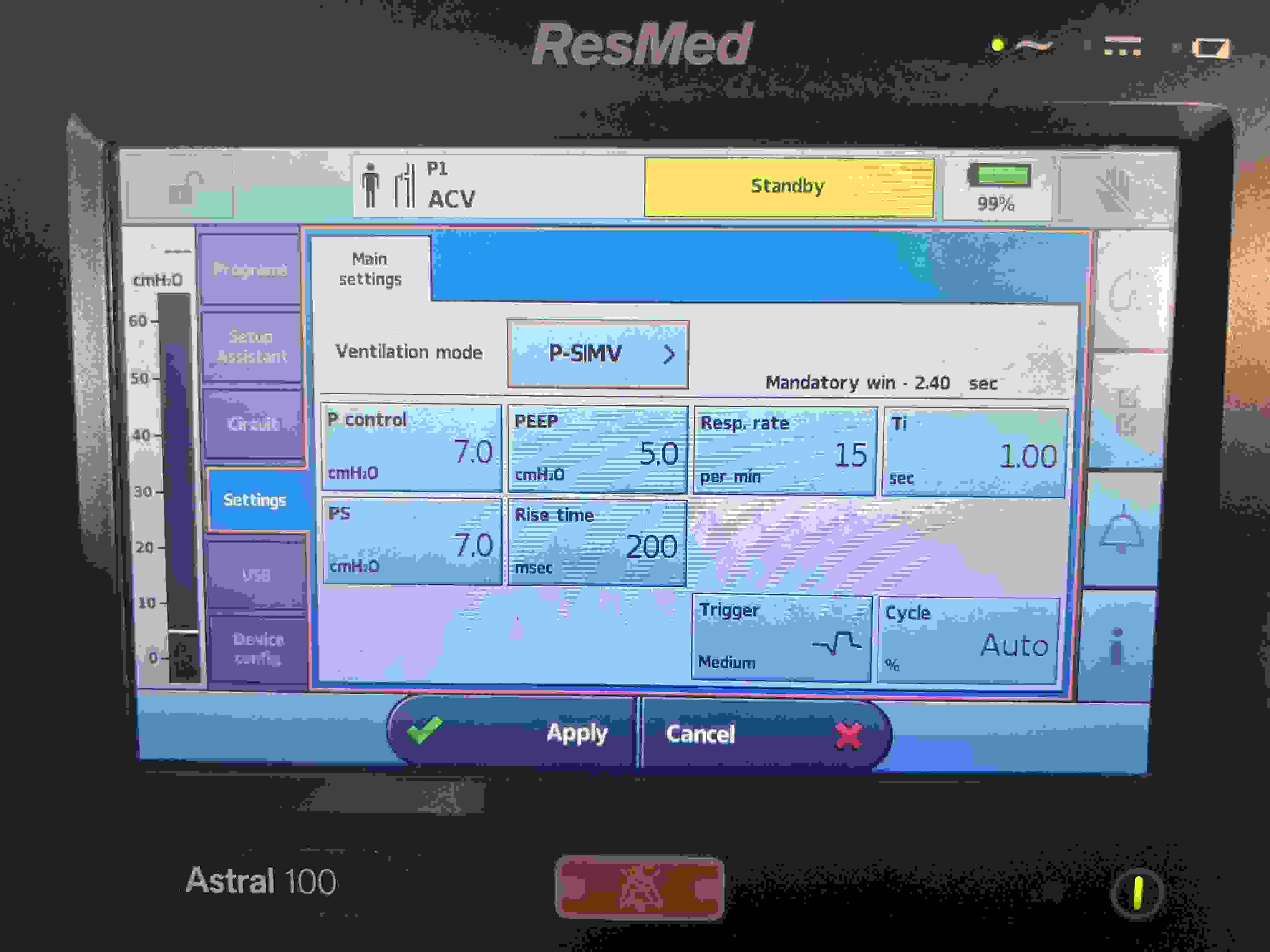
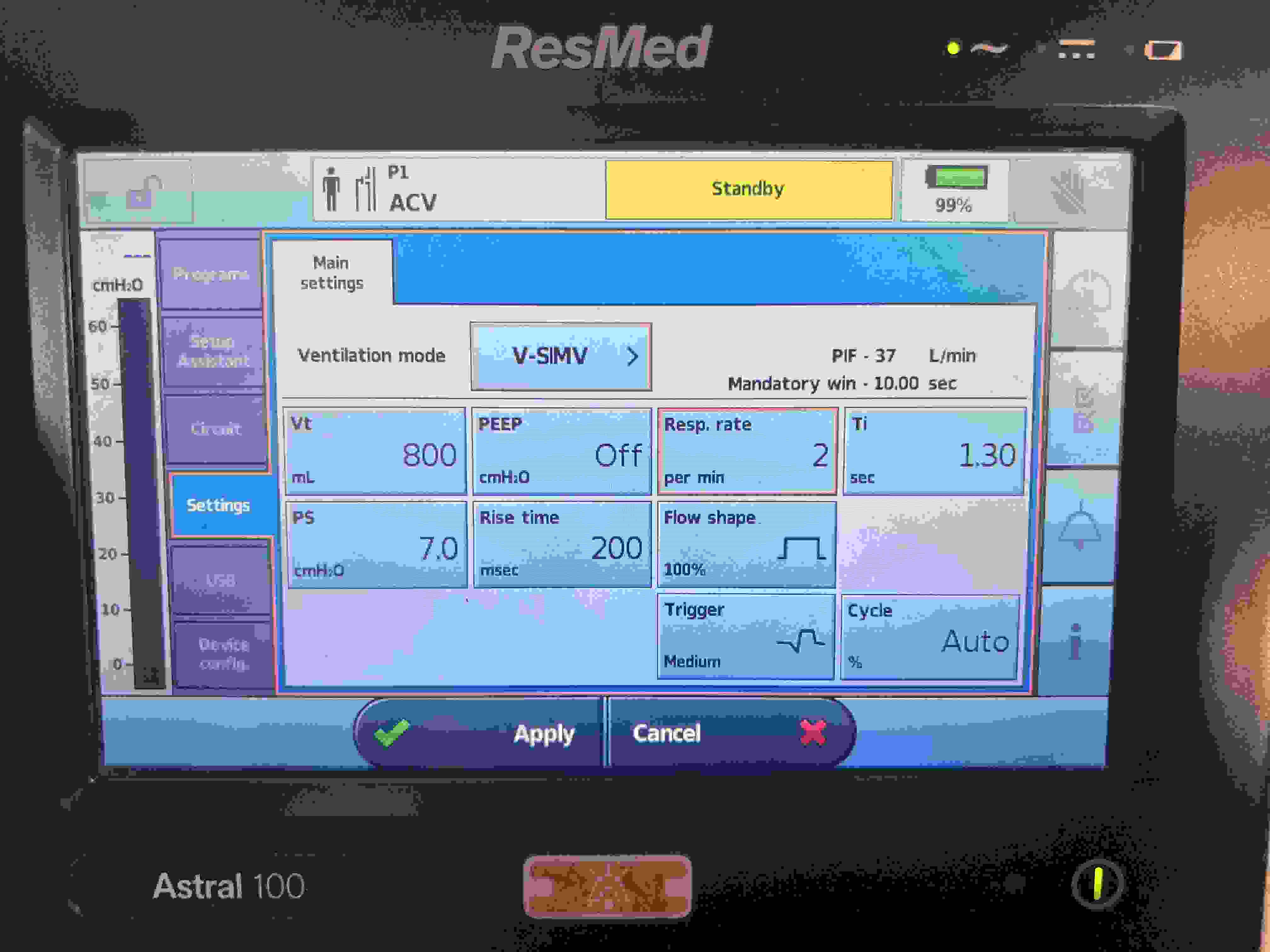
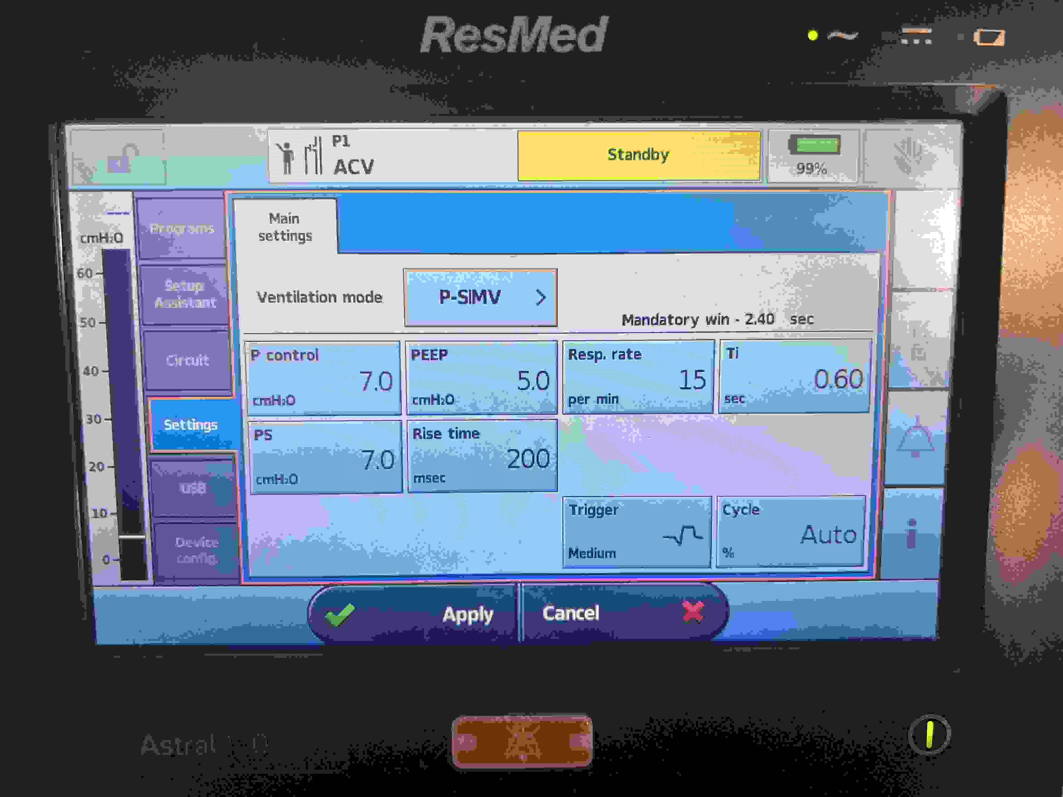
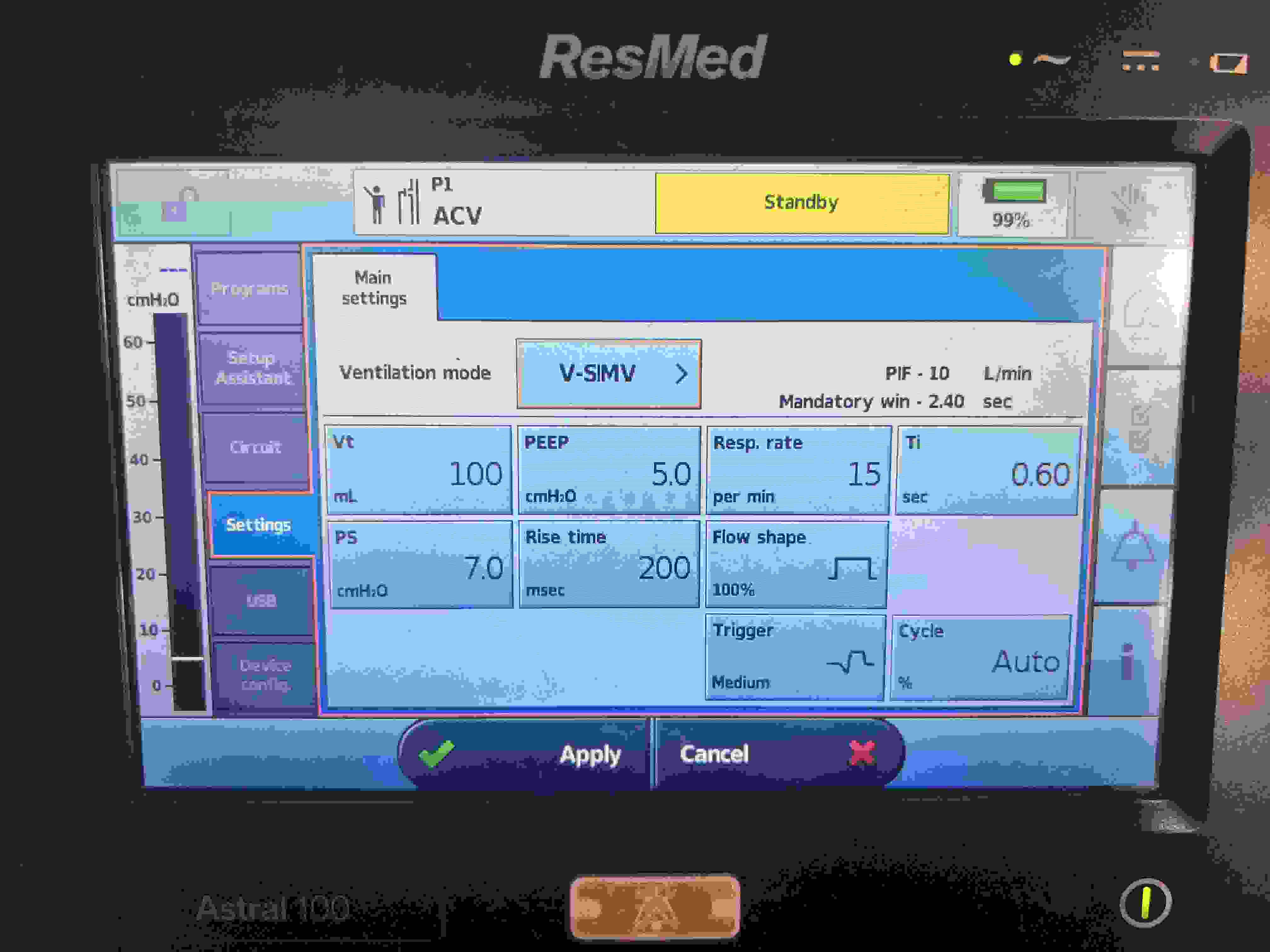
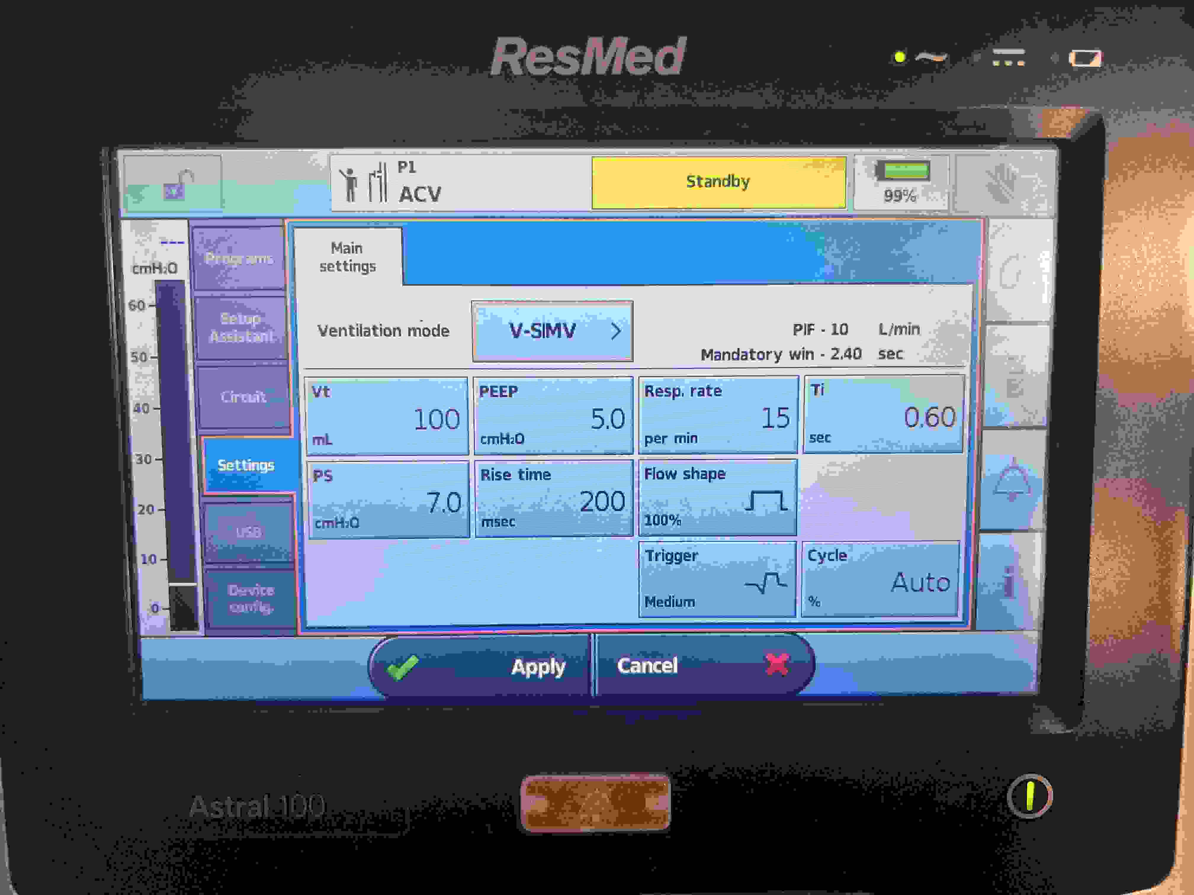
SIMV VC + PS
Volume (Mandatory) & Pressure (Spont.)
Tidal Volume for Mandatory Breaths (6–8 mL/kg IBW)
SIMV Rate
Pressure Support (PS) (≈5–20 cmH₂O) for spontaneous breaths
FiO₂
PEEP
Inspiratory Flow/I:E Ratio (I:E ~1:2) for mandatory breaths
Trigger sensitivity (Flow trigger: 1–5 L/min)
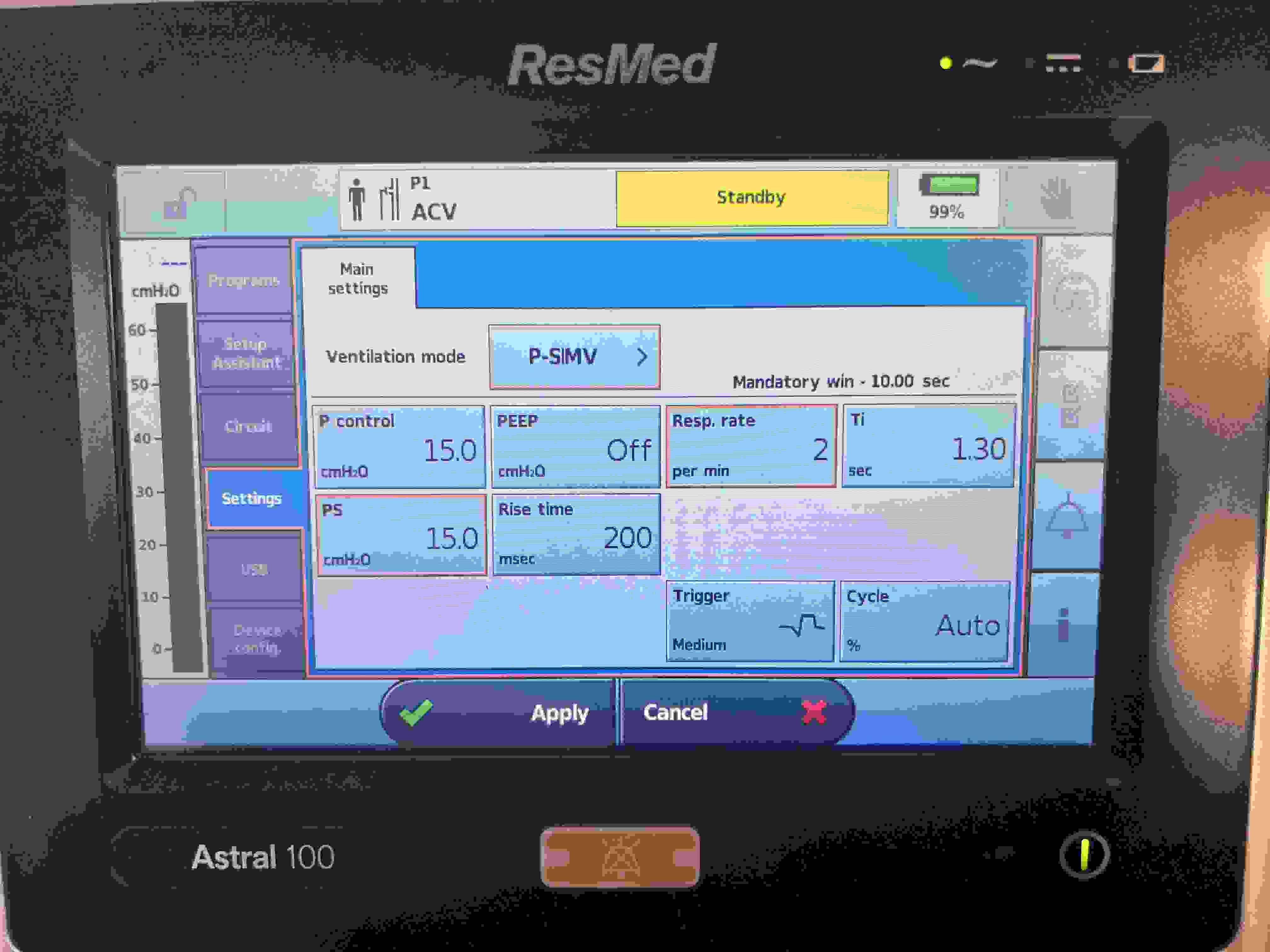
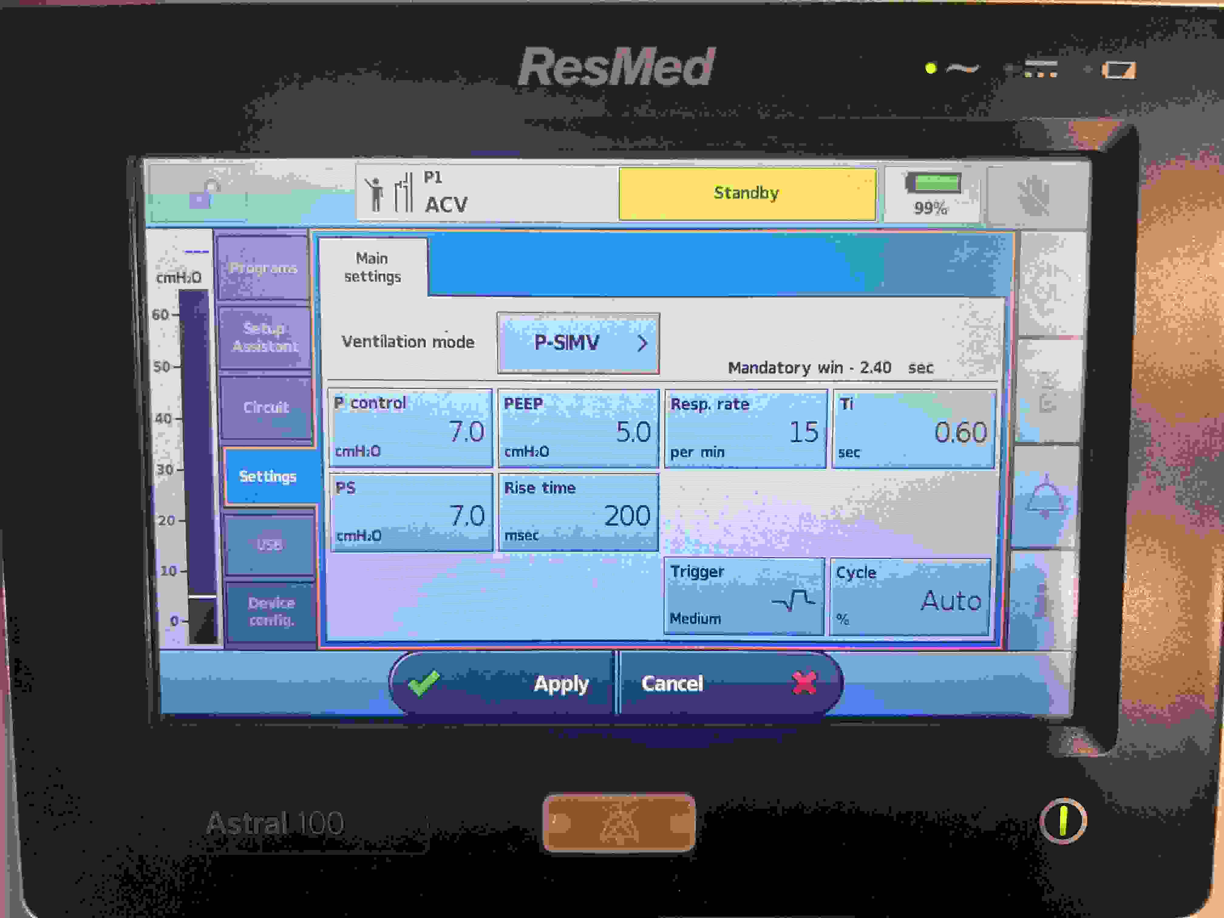
SIMV PC + PS
Pressure (Mandatory) & Pressure (Spont.)
Set Inspiratory Pressure (≈10–25 cmH₂O) for Mandatory Breaths
SIMV Rate
Pressure Support (PS) (≈5–20 cmH₂O) for spontaneous breaths
FiO₂
PEEP
Inspiratory Time or I:E Ratio (I:E ~1:2) for mandatory breaths
Trigger sensitivity (Flow trigger: 1–5 L/min)
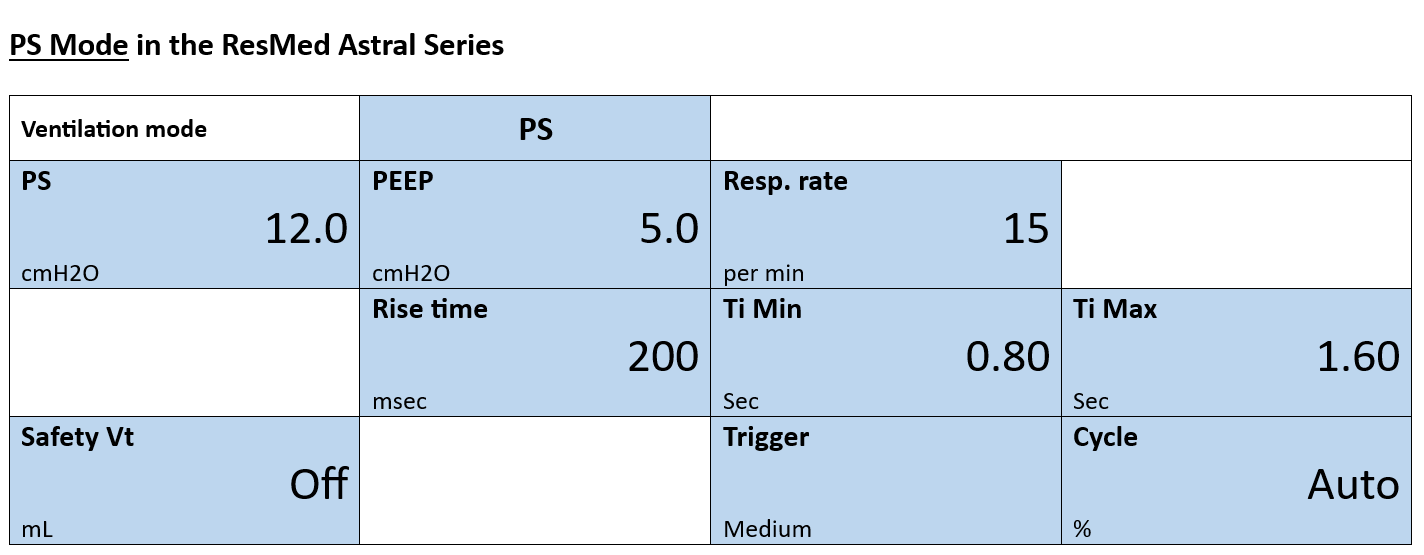
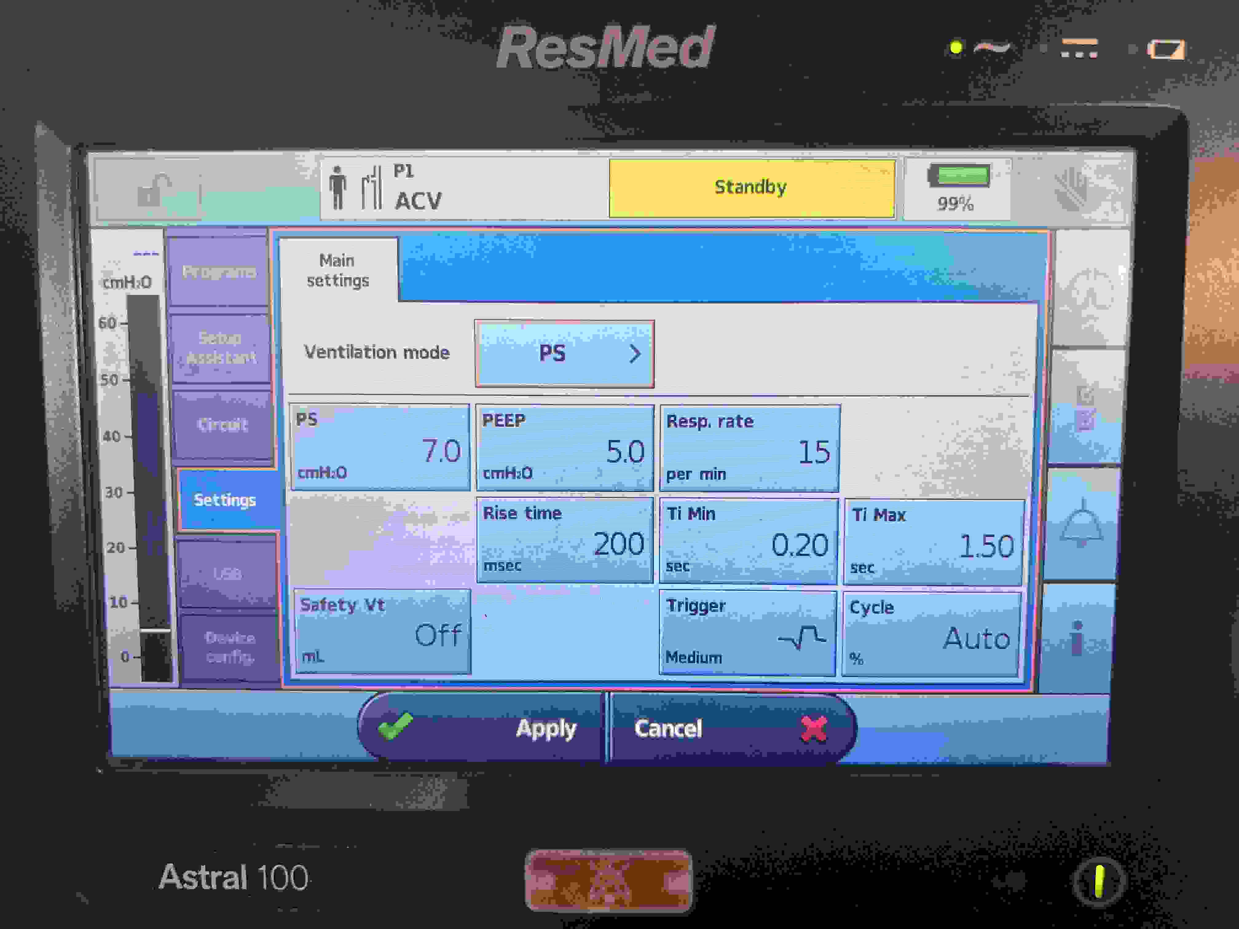
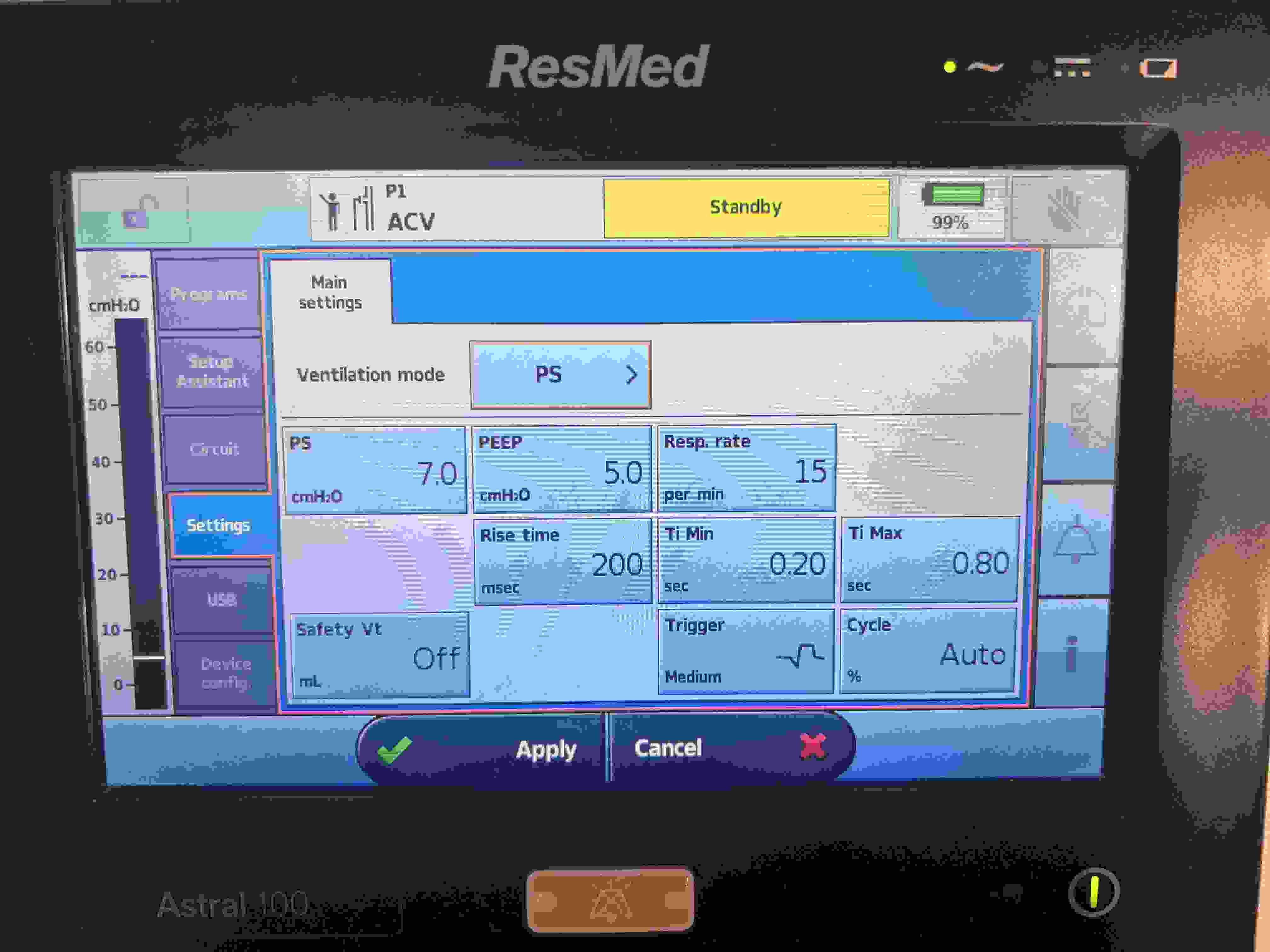
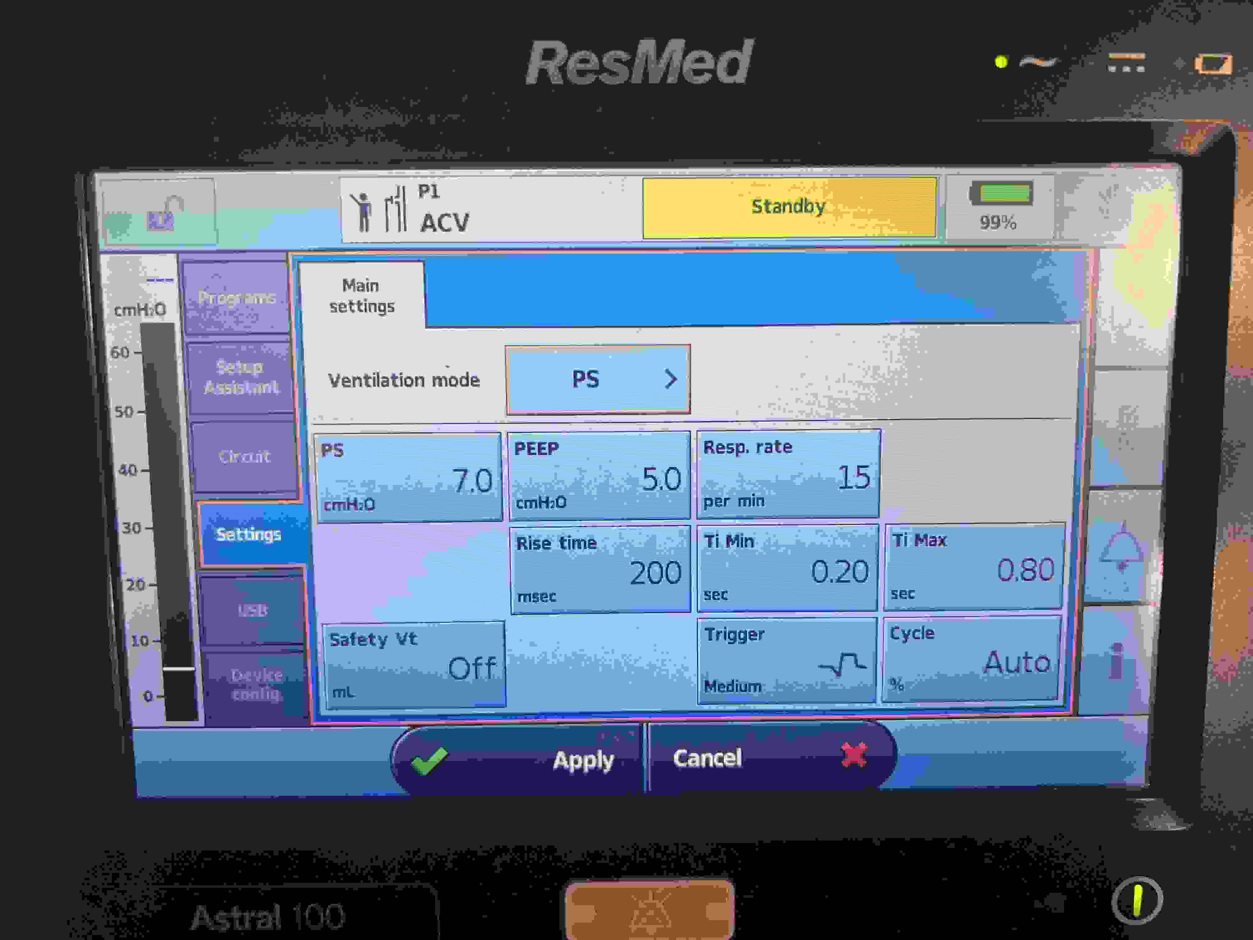
PS (Pressure Support)
Pressure (Spontaneous)
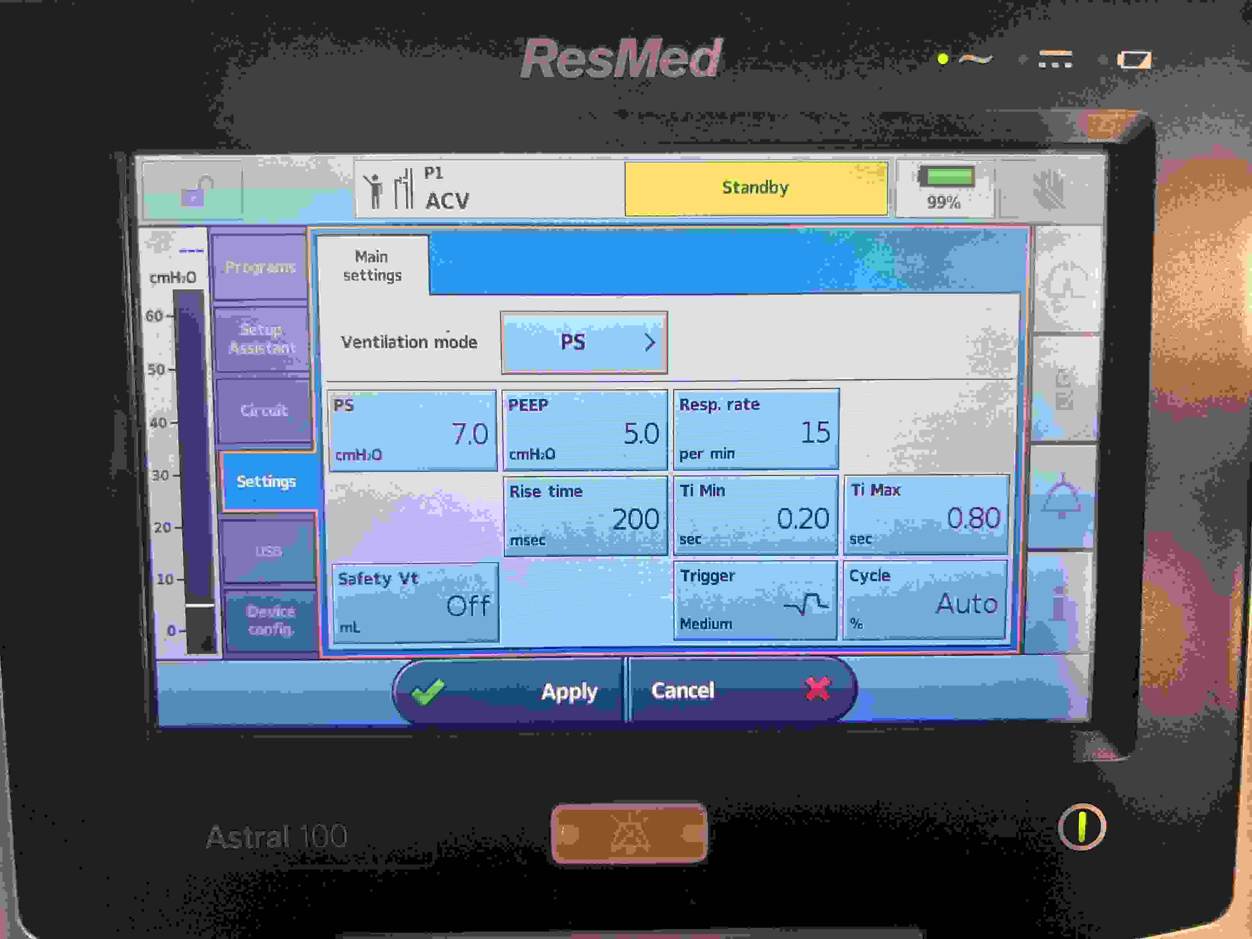
Pressure Support (PS) (≈5–20 cmH₂O)
FiO₂
PEEP
Trigger sensitivity (Flow trigger: 1–5 L/min)
Rise time (≈0.1–0.2 s)
% Pressure Support is for intubated or non-intubated patients, depending on their needs.
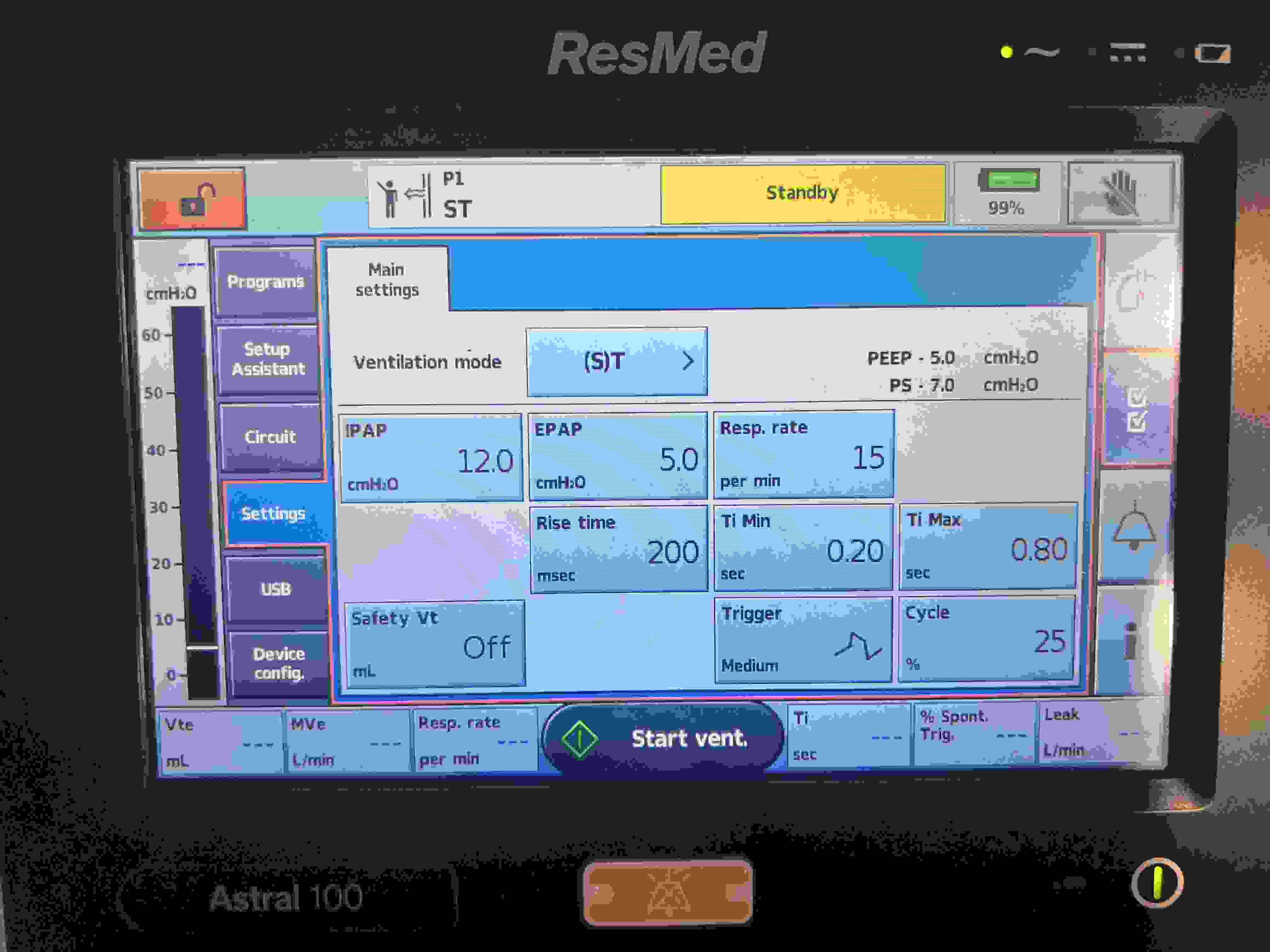
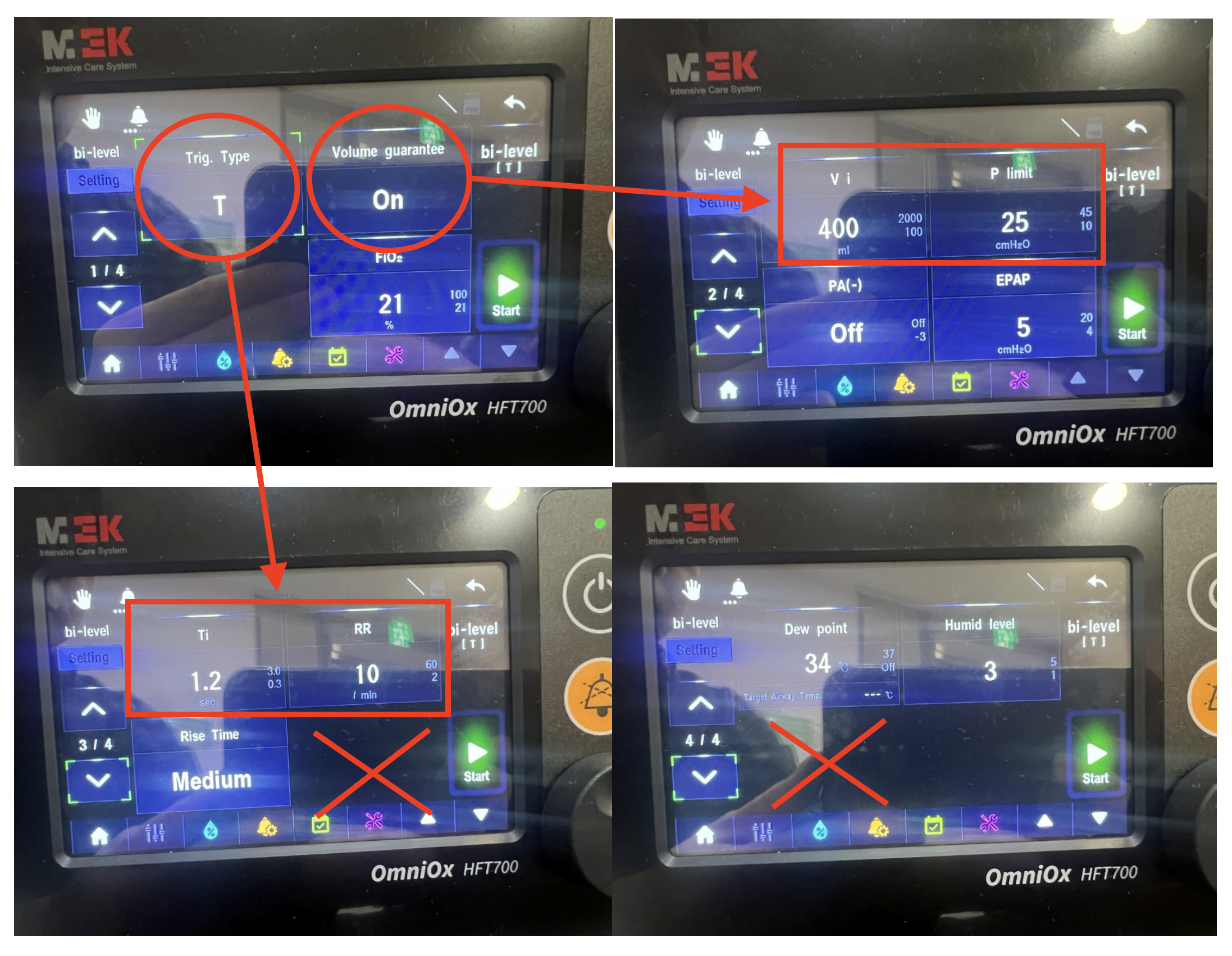
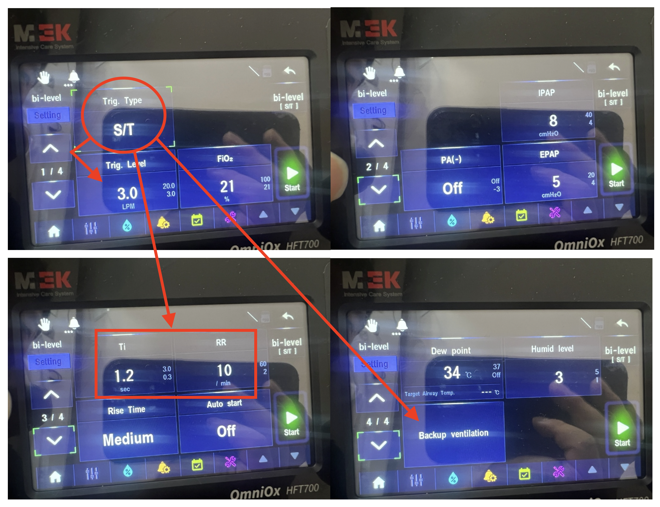
ST (Spontaneous/Timed, NIV)
Pressure (with backup)
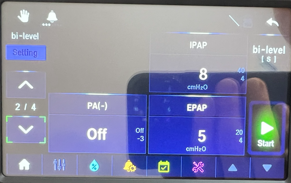
IPAP (≈10–20 cmH₂O)
EPAP (≈5–10 cmH₂O)
Backup RR
FiO₂ (if available)
Rise time (≈0.1–0.2 s)
Trigger and cycle sensitivity (Flow trigger: 1–5 L/min)
BiPAP (NIV)
Pressure (Spontaneous)
IPAP (≈10–20 cmH₂O)
EPAP (≈5–10 cmH₂O)
FiO₂ (if available)
Backup RR & inspiratory time (Inspiratory Time ~0.8–1.2 s)
Rise time (≈0.1–0.2 s), trigger sensitivity (Flow trigger: 1–5 L/min)
Trigger and Cycle Sensitivity: Flow trigger: 1–5 L/min
Flow or Pressure Support: PS ≈5–20 cmH₂O (if provided)
Ventilator modes such as ST (Spontaneous/Timed, Non-Invasive Ventilation) and SV (Spontaneous Ventilation) provide respiratory support tailored to various clinical needs. These modes range from offering a combination of spontaneous and timed breaths to facilitating entirely patient-driven breathing efforts. Modern ventilators often integrate ST and SV modes to enhance flexibility and adaptability in managing patient care, particularly in non-invasive applications.
ST (Spontaneous/Timed, Non-Invasive Ventilation)
ST mode, also known as Spontaneous/Timed Non-Invasive Ventilation (NIV), delivers patient-initiated spontaneous breaths combined with ventilator-delivered timed breaths. It is intended for patients capable of breathing spontaneously but who require additional support to maintain adequate ventilation and oxygenation.
SV (Spontaneous Ventilation)
SV mode relies entirely on the patient’s own respiratory drive, providing minimal or no machine assistance. It is suitable for patients who are largely breathing independently but may benefit from occasional support to reduce the work of breathing.
ST, SV (Integrated ST & SV Modes)
Modern ventilators that integrate ST and SV modes offer notable advantages, ensuring that respiratory support is appropriately matched to changing patient conditions.
Enhanced Flexibility:
Integrating ST and SV allows tailoring of respiratory support to the patient’s evolving status. For example, a patient may benefit from more controlled assistance at one point and require greater freedom for spontaneous breathing at another. This dynamic adjustment helps maintain optimal ventilation with minimal manual intervention.
Optimized Patient Comfort and Compliance:
By providing both timed mandatory breaths and opportunities for spontaneous ventilation, integrated modes align with natural breathing patterns, often improving patient comfort and reducing the perception of reliance on a machine. Enhanced synchrony between the patient and ventilator may also decrease sedation requirements and facilitate a more rapid recovery.
Improved Clinical Outcomes:
Integrated ST and SV modes support gradual weaning from mechanical ventilation by offering appropriate assistance as respiratory function improves. They can adapt to changes in a patient’s respiratory mechanics, ensuring consistent and adequate support without excessive intervention.
Comprehensive Support for Various Clinical Scenarios:
These integrated modes are beneficial in a wide range of clinical situations, from acute respiratory distress to chronic respiratory conditions. The ability to deliver ST and SV non-invasively expands their applicability to patients who may not tolerate invasive ventilation, improving overall patient management strategies.
Written on December 12th, 2024
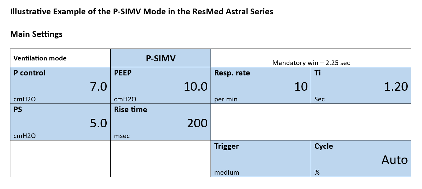
Ventilator Parameter Settings for Patient Transfer
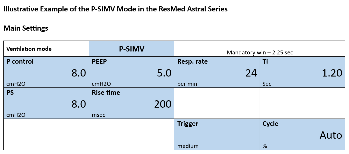
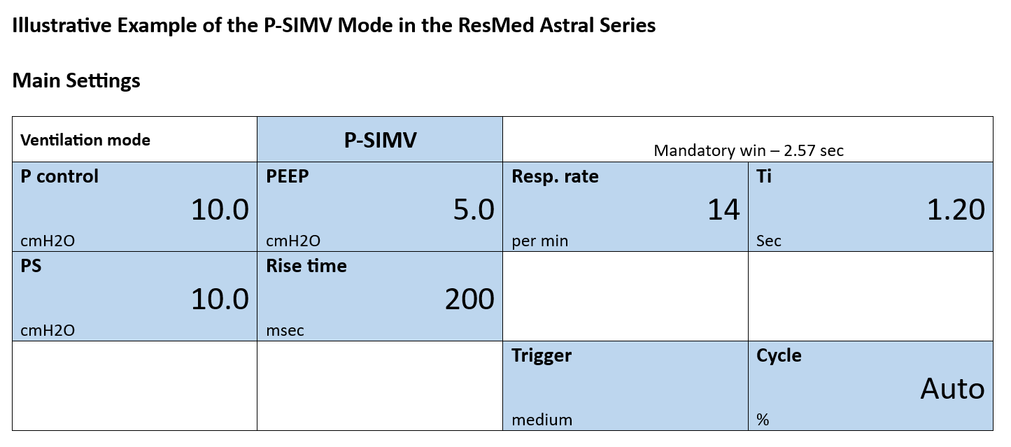
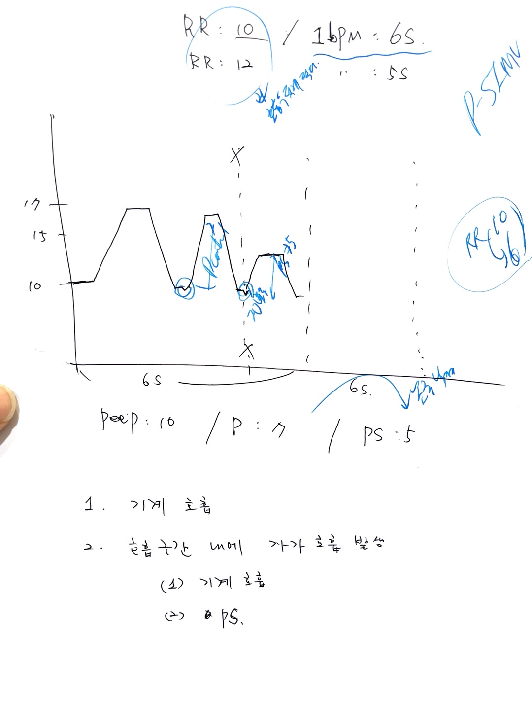
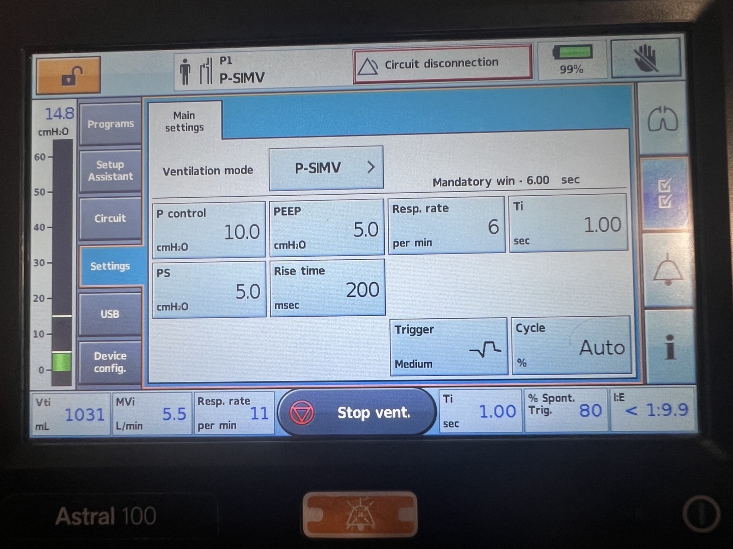
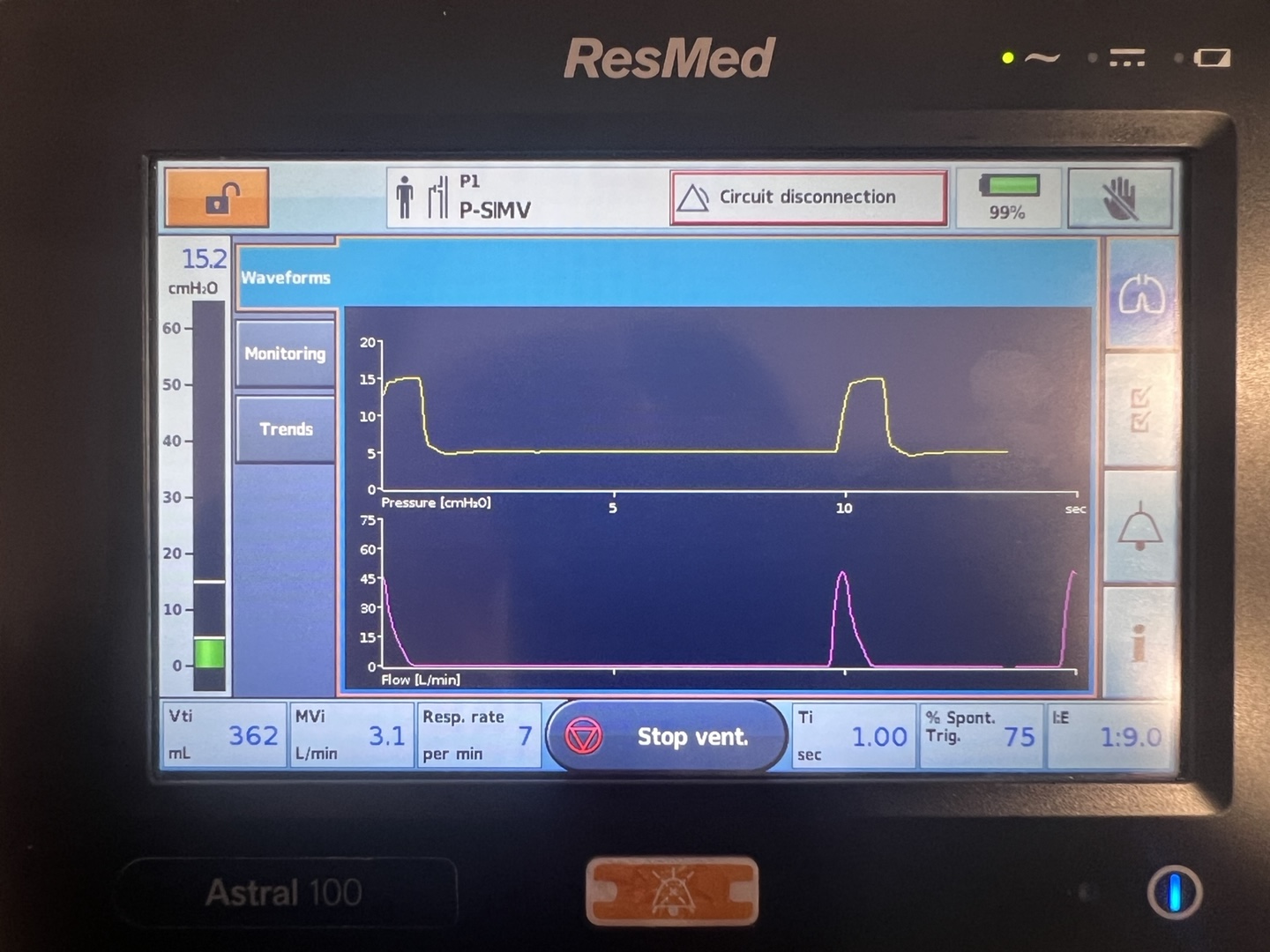
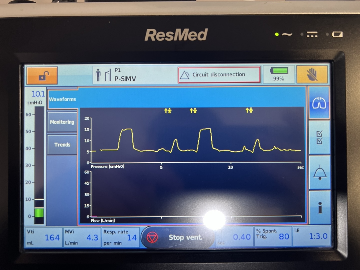
SIMV-PCV-PS is a ventilator mode that integrates Synchronized Intermittent Mandatory Ventilation (SIMV), Pressure Control Ventilation (PCV), and Pressure Support (PS). This configuration ensures that the ventilator delivers a set number of mandatory breaths at a predetermined pressure as defined by PCV. These breaths are synchronized with any spontaneous efforts by the patient, maintaining necessary ventilation support even in the absence of patient-initiated breathing.
In this mode, if the patient initiates a spontaneous breath, the ventilator shifts to Pressure Support (PS) mode. PS applies a consistent pressure during these spontaneous breaths, facilitating easier breathing by reducing the effort needed to inhale. If no spontaneous efforts occur, the ventilator continues with mandatory PCV breaths, providing uninterrupted support. Therefore, PS is only active during patient-initiated breathing; otherwise, ventilation defaults to the controlled settings of PCV.
Vsens (Volume Sensitivity): Activates support when a spontaneous breath exceeds a preset volume threshold.
Esens (Expiratory Sensitivity): Ends inspiratory support to allow natural exhalation based on the patient's breath.
Ti (Inspiratory Time): Specifies the duration of pressure application during each ventilator-assisted breath.
Pi (Inspiratory Pressure): Sets the pressure during the inspiratory phase to achieve the target breath volume in PCV mode.
Psupp (Pressure Support): Provides additional pressure during spontaneous breaths to ease inhalation.
Rate (Breathing Rate): Ensures a minimum set number of breaths per minute to meet ventilatory needs.
PEEP (Positive End-Expiratory Pressure): Keeps the lungs slightly inflated at the end of exhalation to prevent collapse and enhance oxygenation.
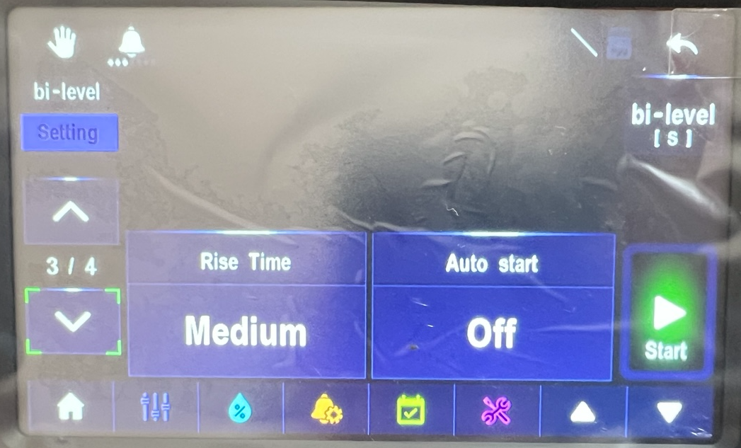
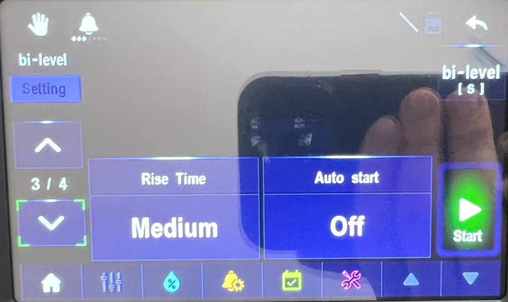
Rise Time: Adjusts the speed at which the set inspiratory pressure is reached during a breath in PS mode, enhancing patient comfort and synchrony with the ventilator.
Short practical guide to anion gap in mechanically ventilated patients
This concise guide emphasizes rapid, bedside interpretation of the anion gap (AG) in ventilated patients. Mechanical ventilation modulates PaCO₂ and arterial pH, but it does not correct the underlying metabolic component. The AG helps determine whether unmeasured anions are accumulating (high AG metabolic acidosis) or whether bicarbonate loss/chloride gain predominates (normal AG metabolic acidosis). Albumin-adjusted AG and disciplined use of compensation formulas prevent missed diagnoses in hypoalbuminemia and mixed disorders.
I. When and why to check
Trigger: Any low HCO₃⁻, unexplained acidemia, rising lactate, shock, DKA, renal failure, toxin concern, or large-volume saline resuscitation.
Simultaneous sampling: ABG/VBG with basic metabolic panel (Na, Cl, HCO₃⁻) and albumin to avoid time offsets.
Trend, not snapshot: Reassess AG as resuscitation proceeds; closure or persistence of the gap guides therapy.
II. Bedside equations
\[ \textbf{Anion Gap (without K)}:\quad AG = [Na^+] - \big([Cl^-] + [HCO_3^-]\big) \]
Notes: Use local laboratory normal AG (commonly ~12 mEq/L when K is excluded). Correct for albumin when hypoalbuminemia is present to avoid missing HAGMA.
III. Practical calculation and interpretation sequence
Confirm metabolic acidosis on ABG/chemistry: low pH and/or low HCO₃⁻. Compare measured PaCO₂ with Winter’s expected value to classify compensation as appropriate or inappropriate.
Calculate AG = Na − (Cl + HCO₃⁻). Apply albumin correction when albumin < 4 g/dL.
Classify as elevated AG versus normal AG using local reference and clinical context.
If elevated AG: obtain lactate, serum ketones/β‑hydroxybutyrate, renal indices, and toxicology (toxic alcohols, salicylate) without delay; begin mechanism‑specific therapy in parallel.
If normal AG: seek bicarbonate loss (GI, renal) and iatrogenic chloride load; consider bicarbonate replacement when indicated and adjust fluids.
Screen for mixed disorders: compute ΔAG, ΔHCO₃, and the delta ratio; discordances suggest concurrent processes that may change ventilator and fluid strategies.
IV. Common scenarios in ventilated patients: recognition and first moves
Lactic acidosis in shock or severe hypoxemia (HAGMA)
Pattern: Elevated AG; elevated lactate; possible inadequate respiratory compensation if PaCO₂ > Winter’s predicted.
Immediate actions: Restore perfusion and oxygen delivery (fluids, vasoactives, source control for sepsis), serial lactate and AG monitoring. Consider temporary IV bicarbonate if pH ≤ 7.1 while definitive therapy proceeds.
Ventilator notes: Increase minute ventilation to meet expected PaCO₂ (per Winter’s) without causing volutrauma; reassess pH after hemodynamic optimization.
Diabetic ketoacidosis (HAGMA)
Pattern: Elevated AG with ketonemia/ketonuria; potassium may be high initially but total body potassium is depleted.
Immediate actions: IV insulin, isotonic fluids, vigilant potassium repletion. Follow AG closure as a resolution marker in addition to glucose control.
Ventilator notes: Emulate compensatory hyperventilation (avoid relative hypoventilation that abruptly increases PaCO₂). Titrate minute ventilation to predicted PaCO₂ until acidosis improves.
Acute or chronic renal failure (HAGMA ± NAGMA)
Pattern: Elevated AG from retained acids; concomitant NAGMA possible.
Immediate actions: Consider urgent renal replacement therapy when severe acidemia, hyperkalemia, or volume issues coexist. Alkali therapy as bridge if needed.
Ventilator notes: Maintain adequate ventilation; after dialysis, AG should fall and pH improve.
Immediate actions: Antidotes when applicable (e.g., fomepizole), aggressive alkalinization in salicylates, and early hemodialysis for severe cases. Serial AG to confirm clearance.
Ventilator notes: In salicylate toxicity, preserve hyperventilation (high minute ventilation) to avoid abrupt PaCO₂ rise that worsens CNS toxicity.
Iatrogenic hyperchloremic acidosis after large-volume saline (NAGMA)
Pattern: Normal AG with elevated Cl and low HCO₃⁻; base deficit present.
Immediate actions: Switch to balanced crystalloids (e.g., lactate- or acetate‑buffered solutions). Consider bicarbonate infusion if acidemia is hemodynamically significant.
Ventilator notes: Temporary increase in minute ventilation may be needed; correct chloride load to resolve the acidosis.
GI bicarbonate loss (diarrhea, pancreatic/biliary fistula) (NAGMA)
Pattern: Normal AG with low HCO₃⁻ and high Cl; potential hypokalemia.
Immediate actions: Address source of losses; replace bicarbonate and potassium.
Ventilator notes: Provide respiratory compensation while repletion is underway.
Type IV renal tubular acidosis (often in diabetes or adrenal disease) (NAGMA)
Pattern: Normal AG with hyperkalemia; mild-to-moderate acidemia.
Immediate actions: Consider mineralocorticoid support, loop/thiazide diuretics, or potassium-binding strategies; provide bicarbonate as needed.
Ventilator notes: Avoid permissive hypercapnia when pH is marginal; modestly augment ventilation until metabolic therapy takes effect.
ARDS with permissive hypercapnia plus superimposed metabolic acidosis
Pattern: Low pH from combined respiratory and metabolic components (AG may be high or normal).
Immediate actions: If pH < 7.15 or hemodynamics are compromised, consider cautious buffering and a temporary, small increase in minute ventilation while lung‑protective strategy is preserved.
Ventilator notes: Balance pH goals with lung‑protective limits; reassess after the metabolic driver is treated (e.g., lactate reduction).
Normal AG: look for GI/renal HCO₃⁻ loss or chloride load; change fluids to balanced solutions; consider bicarbonate therapy as indicated.
Delta–delta: unmask mixed disorders that alter ventilator targets and fluid choices.
Reassess frequently: track AG (or AGcorr) and pH as therapy proceeds; adjust ventilation as the metabolic disturbance resolves.
Written on July 27, 2025
ABGA-Based Acid–Base & Anion‐Gap Monitor for Ventilation & Dialysis
Pressure-Volume Loops and Lung Compliance in Ventilated Patients
I. Basic Concepts: Pressure, Volume, and Compliance
Understanding pressure-volume (P–V) loops is fundamental for clinicians managing ventilation. In a P–V loop for the lung, the Y-axis represents lung volume and the X-axis represents pressure (typically the pleural or transpulmonary pressure). Lung compliance is defined as the change in volume per change in pressure:
\( Compliance = \frac{\Delta V}{\Delta P} \). This means compliance is essentially the slope of the P–V curve at any given point. A steeper slope (larger angle θ) indicates higher compliance, meaning the lung volume changes substantially for a small pressure change. Conversely, a flatter slope indicates low compliance, meaning the lung is stiff and requires larger pressure changes to produce volume changes.
The normal pressure-volume relationship of the lung is non-linear and sigmoid-shaped. At low lung volumes, initially the curve is flat (low compliance), then it becomes steeper at moderate volumes (high compliance), and flattens again at high volumes as the lungs approach their maximal capacity. This shape reflects the lung’s elastic properties: it is harder to begin inflating completely collapsed alveoli, easier to inflate them in a mid-volume range once open, and harder again to further stretch them near total lung capacity due to elastic limits. Thus, compliance is not constant; it is greatest in the mid-range of lung volumes and lowest at the extremes.
II. Hysteresis and Surfactant in the Normal Lung
When measuring a lung’s P–V loop during inflation (inspiration) and deflation (expiration), a phenomenon called hysteresis is observed. The inspiratory and expiratory curves do not overlap; for a given pressure, the lung volume is higher during deflation than during inflation. This occurs because of the behavior of surfactant and alveolar surface tension during the breathing cycle.
During inspiration, as alveoli expand, the surfactant molecules on their inner surface become more spread out (less concentrated per area). This reduction in surfactant density causes an increase in surface tension in the alveoli, which in turn decreases compliance. In other words, as the alveolus enlarges, it resists further stretch more due to rising surface tension.
During expiration, the opposite occurs: alveoli become smaller, surfactant molecules become more densely packed on the alveolar surface, which lowers the surface tension. The reduced surface tension makes the lungs more compliant during deflation. Because of this surfactant behavior, the deflation limb of the P–V loop has higher volumes at equivalent pressures (higher compliance) than the inflation limb. Hysteresis indicates that additional energy is needed during inflation to recruit and open alveoli (overcoming surface tension and initial stiffness), whereas deflation is aided by surfactant concentrating and maintaining openness of alveoli.
Surfactant, produced by type II alveolar cells, is critical for normal lung compliance. It lowers the alveolar surface tension, particularly when alveoli are small. By dynamically adjusting surface tension (increasing tension when stretched, decreasing when compressed), surfactant stabilizes alveoli and reduces the work of breathing. Without adequate surfactant, inflation would require extraordinarily high pressures, and small alveoli would collapse on expiration. The presence of surfactant explains why normal lungs can inflate and deflate along a workable loop rather than snapping open or collapsing. Hysteresis on the P–V loop graphically represents the effects of surfactant and alveolar recruitment.
III. Saline-Filled vs. Air-Filled Lungs
An illuminating experiment in pulmonary physiology is comparing a lung inflated with air to one inflated with fluid (such as saline). In a saline-filled lung, the air–liquid interface inside alveoli is absent, and thus surface tension forces are eliminated. The P–V curve for a saline-filled lung is dramatically different from that of an air-filled lung. With saline inflation, the lung exhibits much higher compliance and minimal hysteresis. This means that far less pressure is required to achieve the same volume. In fact, an air-filled lung typically requires roughly three times the transpulmonary pressure to reach a given volume compared to a saline-filled lung. The air-filled lung’s P–V loop lies to the right of the saline curve (indicating higher pressure needed) and shows a wider gap between inflation and deflation limbs (greater hysteresis). By contrast, the saline-filled lung’s curve is steeper and the inflation and deflation limbs nearly overlap (negligible hysteresis).
This comparison demonstrates the huge impact of surface tension in normal (air-filled) lungs. In the air-filled lung, a significant portion of the applied pressure is used to overcome surface tension at the alveolar air–water interface, especially at lower lung volumes when alveoli are small. In the saline lung, only the elastic resistance of lung tissue (collagen and elastin fibers) must be overcome, since surface tension forces are absent. Therefore, the saline-filled lung has less elastic recoil and much greater compliance. The difference between the air and saline P–V loops at any volume essentially quantifies the pressure needed to overcome surface tension. At low lung volumes, surface tension normally makes inflation difficult (atelectatic alveoli require a critical opening pressure). At high volumes, tissue elasticity becomes more important. By eliminating surface tension, saline inflation reveals the “ideal” compliance if only tissue forces were in play, and it confirms that surfactant and surface tension are key determinants of lung mechanics. Clinically, this underscores the importance of surfactant in reducing the work of breathing and the tendency of alveoli to collapse.
IV. Comparative pressure–volume curves
(
normal,
low compliance,
high compliance ,
↑ airway resistance
)
The chart depicts four representative pressure–volume loops anchored at the same
residual-volume starting point (≈ 7 % TLC) to highlight how differing
mechanical properties alter the loop shape:
Normal – The cyan loop follows a gentle
sigmoid path: moderate slope in mid-range volumes and modest hysteresis.
It reflects the balanced opposition of elastic recoil and surfactant-mediated
surface-tension reduction typical of healthy lung parenchyma.
Low compliance – The ultramarine loop is
flattened and right-shifted. A larger pressure rise is required to achieve
each volume increment because stiff alveolar walls
(e.g. interstitial fibrosis, chest-wall restriction) sharply limit
distensibility. The narrower loop area signifies little resistive work but
high elastic work.
High compliance – The green loop is
steep and left-shifted. Small pressure changes suffice to produce large
volume changes owing to loss of elastic tissue or abundant surfactant
(e.g. emphysema, acute surfactant therapy). Although inflation is easy,
elastic recoil is weak, predisposing to air trapping and lower driving
pressures during ventilation.
↑ airway resistance – The pink loop
shares the normal slope but is noticeably “fatter.” Inflation follows a
rightward track as pressure is spent overcoming flow
resistance; deflation returns on a leftward track as resistive pressure
dissipates. The enlarged enclosed area represents added work of breathing
without a change in static compliance, characteristic of obstructive airway
disease.
In clinical terms, a low-compliance loop warns that higher
plateau pressures (and lower tidal volumes) may be required for safe
ventilation, whereas a high-compliance loop demands vigilance for
overdistension despite seemingly low pressures. A wide, resistive loop
suggests prolonging expiratory time, reducing inspiratory flow, or
administering bronchodilators to limit the excessive work imposed by
airway narrowing.
V. “Fishtail” pressure–volume loop
(orange curve illustrating airway-opening and closing phenomena)
The orange “fishtail” pattern is frequently observed when a spontaneously breathing
patient is connected to a pressure-targeted ventilator:
Negative-pressure tail. A brief patient-generated drop in airway pressure
(–5 cm H2O)
signals inspiratory effort and triggers the ventilator;
little volume enters because alveoli remain closed.
Airway-opening (critical) pressure. At ~3 cm H2O,
a “knee” appears; once this threshold is crossed,
collapsed units pop open and compliance rises sharply.
Rapid recruitment. Beyond the knee, the curve steepens,
reflecting efficient filling of newly patent alveoli and reduced pressure cost.
Deflation limb. During expiration, volume remains higher than on
inspiration until the closing pressure is reached, so the loop’s low-pressure
segment does not retrace the tail—hence the characteristic fish-tail silhouette.
Clinically, the fishtail alerts the practitioner to repeated cyclic opening
and closing—a major source of atelectrauma. Strategies such as raising PEEP
above the airway-opening pressure or performing a gentle recruitment manoeuvre
can eliminate the tail, stabilise alveoli, and reduce ventilator-induced lung
injury.
VI. Factors Affecting Lung Compliance
Changes in Elastic Recoil of Lung Tissue
Lung compliance is strongly influenced by the elastic properties of the lung tissue itself, primarily due to components like elastin and collagen in the alveolar walls. Any condition that alters these elastic fibers will change compliance:
Loss of Elastic Tissue (Increased Compliance): When elastic recoil is reduced, the lungs become easier to distend. A prime example is pulmonary emphysema, in which the destruction of alveolar walls and elastin fibers leads to “floppy” lungs. Emphysematous lungs have high compliance – they inflate easily with small pressure changes. However, because of the lost elastic recoil, they have difficulty expelling air (air trapping), and the lung tends to remain hyperinflated (barrel chest appearance).
Aging (Increased Compliance): In normal aging, gradual changes in elastin and collagen make the lungs more distensible. Elderly individuals often have higher lung compliance compared to younger adults. The lung tissue offers less recoil, contributing to an increased residual volume and a slightly elevated FRC (functional residual capacity) as the chest wall expands outward more.
Fibrosis or Scar Tissue (Decreased Compliance): Conditions that increase elastic recoil or stiffness will reduce compliance. An example is pulmonary fibrosis (an intrinsic restrictive lung disease), where chronic inflammation or interstitial disease leads to deposition of fibrous tissue in the lung. The lungs become stiff and difficult to inflate – compliance is low, so a large pressure change yields only a small volume change. Patients with fibrotic lungs have shallow, rapid breathing because their lungs resist expansion.
Extrinsic Restrictive Factors (Decreased Overall Compliance): Factors outside the lung can also reduce the ease of lung expansion. For instance, severe obesity, chest wall deformities (like kyphoscoliosis), or pleural diseases (like large pleural effusions) restrict lung expansion from the outside. While the intrinsic lung tissue might have normal elasticity, the total respiratory system compliance is reduced. Greater pressure (muscle effort or ventilator force) is required to expand the lungs and chest wall together. Neuromuscular weakness (inadequate muscle force) can similarly make it effectively harder to expand the lung, though it does not change lung tissue stiffness per se.
Changes in Alveolar Surface Tension (Surfactant Effects)
The other major determinant of compliance is alveolar surface tension, governed by surfactant at the air–water interface inside alveoli. Several conditions influence surface tension and thereby lung compliance:
Surfactant Deficiency (Decreased Compliance): If surfactant is inadequate or ineffective, surface tension in alveoli remains high, making the lungs much harder to inflate. The classic example is neonatal respiratory distress syndrome (RDS), seen in premature infants whose immature lungs do not produce enough surfactant. High surface tension causes widespread alveolar collapse (atelectasis) and very low compliance – tremendous effort or ventilator pressure is required to generate normal tidal volumes. Several perinatal factors can predispose to surfactant deficiency in newborns, including prematurity (surfactant production ramps up late in gestation), maternal diabetes leading to fetal hyperinsulinemia (insulin can antagonize surfactant production), lack of antenatal steroids (glucocorticoids given to the mother help mature the lungs), congenital surfactant protein disorders, or even a precipitous cesarean delivery without labor (less fetal stress hormone release). In these scenarios, the absence or dysfunction of surfactant leads to stiff lungs and impaired gas exchange. A similar surfactant dysfunction can occur in adults with severe lung injury (ARDS), contributing to the markedly decreased compliance seen in ARDS.
Enhanced Surfactant Effect (Increased Compliance): In a normal lung, having adequate surfactant ensures reasonable compliance; there is no common pathological state of “too much surfactant,” but we can consider scenarios where surfactant’s effectiveness is maximized. For instance, the earlier discussion of the pressure-volume hysteresis showed that during expiration (the deflation limb), surfactant becomes more concentrated on alveolar surfaces, which maximally reduces surface tension. Thus, the lung’s compliance is higher during expiration than inspiration in each cycle. Another scenario is therapeutic surfactant administration (such as giving exogenous surfactant to a premature infant with RDS) – this treatment dramatically improves lung compliance by acutely lowering alveolar surface tension.
Elimination of Surface Tension (Extreme Case of Increased Compliance): As discussed in the saline-filled lung experiment, removing the air-liquid interface abolishes surface tension forces. While not a physiological condition (one cannot normally have fluid-filled lungs and breathe), this experiment underscores that if surface tension is eliminated, lung compliance becomes very high. In practice, certain interventions that improve surfactant function or recruit collapsed alveoli mimic some aspects of this – for example, a recruitment maneuver or appropriate positive end-expiratory pressure (PEEP) can help open collapsed alveoli, effectively reducing surface tension-related forces and improving overall compliance of the lung.
For clarity, the effects of various conditions on lung compliance are summarized in the table below:
Condition or Scenario
Compliance Change
Primary Mechanism
Emphysema
↑ Increased
Loss of alveolar elastic tissue (decreased recoil)
High alveolar surface tension (alveoli collapse easily)
VII. Work of Breathing: Normal vs. Obstructive Patterns
The pressure-volume loop also reflects the work of breathing. The work required to inflate the lung is proportional to the area under the inspiratory curve, and the difference between the inspiratory and expiratory curves (the hysteresis area) represents energy lost to overcoming frictional forces and surface tension adjustments. In a normal individual at rest, inspiration is an active process (muscular work is done to expand the thorax and drop the pleural pressure), whereas expiration is passive (the stored elastic energy in the stretched lung is released, recoiling the lung inward and expelling air without muscle effort). Thus, in normal lungs there is work done on inspiration but essentially no active work on expiration during quiet breathing.
In obstructive lung diseases (such as advanced COPD/emphysema or severe asthma), the work of breathing increases substantially and can involve both phases of respiration. Because these patients have narrowed or collapse-prone airways, they must generate more negative pleural pressure during inspiration to overcome airway resistance and fill the lungs. On expiration, instead of the lungs recoiling easily, air becomes trapped due to premature airway closure or obstruction. Patients often have to actively engage expiratory muscles (like the abdominal wall) to push air out, especially when ventilation demand is high. This means work is expended during expiration as well — something not seen in healthy breathing. The total work of breathing (area of the P–V loop) is greatly elevated in obstructive disease.
One visible sign of this increased effort is the use of accessory muscles and intercostal retractions during inspiration. Intercostal retraction refers to the inward pulling of the spaces between the ribs during a forceful or labored inspiration. This occurs when a very negative intrapleural pressure is generated (as the patient struggles to draw air in through obstructed airways), causing the relatively soft tissue between ribs to be sucked inward. The presence of intercostal retractions is an indication of significant negative pressure and respiratory distress. Over time, chronic obstructive disease with air trapping leads to hyperinflation of the lungs; the chest adopts a “barrel chest” configuration (increased anterior-posterior diameter) due to an elevated resting lung volume. In a barrel-chested individual, the lungs are operating at a higher volume even at rest (higher FRC). According to Boyle’s law, expanding the chest increases the volume and thus can lower the pressure in the thoracic cavity; however, in the case of a COPD patient at rest, the intrapleural pressure is often less negative than normal at baseline because the lungs have lost recoil tension. The negative intrapleural pressure we normally observe (approximately –5 cm H2O at end-expiration in a healthy person) is a result of the balanced inward recoil of the lungs and outward spring of the chest wall. In advanced emphysema, lung recoil is diminished, so the chest wall springs outward to a larger resting size. The new equilibrium (barrel chest) involves a somewhat less negative pleural pressure at end-expiration, but the diaphragm is flattened and at a mechanical disadvantage. Additionally, because the lungs start out more inflated, a person with hyperinflation has to do more work to inhale further (they are already on a flatter portion of the P–V curve, with reduced inspiratory reserve). All these factors contribute to the increased work of breathing and potential for respiratory muscle fatigue in obstructive lung disease.
VIII. Implications for Mechanical Ventilation: PEEP and Tidal Volume
Understanding pressure-volume relationships and compliance is crucial when managing patients on mechanical ventilators, as it guides the optimization of ventilator settings such as positive end-expiratory pressure (PEEP) and tidal volume. In a passively ventilated patient (e.g., one who is sedated on volume-controlled ventilation), the ventilator is doing the work of breathing by applying positive pressure to the airways. Essentially, instead of the patient’s muscles making the pleural pressure more negative, the machine increases alveolar pressure to inflate the lungs. This difference in how pressure is generated leads to some physiological and practical considerations:
Positive Pressure vs. Negative Pressure Inflation: In spontaneous (negative-pressure) breathing, pleural pressure drops below atmospheric pressure, and transpulmonary pressure (alveolar minus pleural pressure) increases to draw air in. In mechanical (positive-pressure) ventilation, airway (alveolar) pressure is raised above pleural pressure to push air into the lungs. Consequently, pleural pressure tends to rise (become less negative, or even positive if high pressures are used) during a positive-pressure breath. The P–V loop for mechanical ventilation is often plotted with airway pressure on the X-axis, but conceptually if plotted against pleural pressure, inspiration under positive pressure would show pleural pressure moving toward the positive direction. This can have hemodynamic effects (e.g., high intrathoracic pressure can reduce venous return), but in terms of lung mechanics, the transpulmonary pressure still dictates lung inflation. Clinically, measuring plateau pressure (after an inspiratory pause) and, if available, esophageal pressure as a surrogate for pleural pressure can help determine transpulmonary pressure and thus the effective lung-distending pressure.
Using PEEP to Improve Compliance and Oxygenation: PEEP is a key ventilator setting that maintains a positive pressure in the lungs at end-expiration. By not allowing the lung to deflate completely to atmospheric pressure, PEEP increases the functional residual capacity and prevents alveolar collapse. On the P–V curve, applying an appropriate level of PEEP essentially shifts the starting point of each breath to a higher volume (on the deflation limb of the curve where compliance is higher and alveoli are already open). This minimizes atelectasis and keeps alveoli in a more compliant range of the P–V relationship, thus reducing the work needed for the next inspiration and improving gas exchange. For patients with poor compliance due to surfactant issues or low lung volumes (such as ARDS), setting a sufficient PEEP above the lower inflection point of the pressure-volume curve recruits alveoli and markedly improves effective compliance. However, too much PEEP can push the lung toward overdistension (the flat upper part of the P–V curve), so it must be titrated carefully.
Tidal Volume and Overdistension: The selected tidal volume (VT) interacts with lung compliance to determine the pressures reached during ventilation. In a lung with normal or high compliance (e.g., emphysema), a given tidal volume will generate relatively low airway pressures. But such lungs are prone to overdistension if volumes are excessive, since they offer little resistance until the limits of their structure are reached; extreme overinflation can risk barotrauma or volutrauma (for example, rupturing a bleb in an emphysematous lung causing pneumothorax). In a stiff, low-compliance lung (e.g., fibrotic lung or ARDS), even a moderate tidal volume can produce high plateau pressures. To avoid ventilator-induced lung injury, modern strategies use lower tidal volumes in such patients (lung-protective ventilation), accepting smaller volumes to keep pressures at safe levels. Essentially, when compliance is low, the ventilator’s pressure alarm limits will be reached quickly if tidal volume is too large, indicating that the lung is being overstretched. By adjusting tidal volume to an appropriate level (around 6 mL/kg in ARDS, for instance), one can ensure the lung remains on the safer mid-portion of the P–V curve rather than the flat, injurious upper end.
Compliance Monitoring and Ventilator Adjustments: ICU ventilators often display dynamic P–V loops and calculate compliance. A decreasing compliance (flattening of the P–V slope) can alert clinicians to worsening lung conditions (e.g., developing pulmonary edema, ARDS, tension pneumothorax, or right mainstem intubation causing one-lung ventilation). Conversely, an improving compliance (steeper slope) might indicate resolving pathology or effective recruitment of lung units. Clinicians adjust PEEP, tidal volume, or other settings in response. For example, if the P–V loop suggests many alveoli are not opening until a certain pressure threshold, a recruitment maneuver or a higher PEEP may be used to pop open those units, thereby moving the lung to a more compliant part of the curve. The goal is to ventilate the patient on the optimal portion of the compliance curve – avoiding both the lower extreme (atelectatic, low-volume, low-compliance region) and the upper extreme (overstretched, high-pressure, low-compliance region).
In summary, pressure-volume loops offer invaluable insight into lung mechanics for both spontaneously breathing individuals and mechanically ventilated patients. The slope of these loops (compliance) reflects how easily the lungs inflate, which is determined by elastic tissue recoil and surfactant-mediated surface tension forces. Changes in compliance can signal normal adaptation (aging) or disease processes (emphysema, fibrosis, surfactant deficiency). For the clinician at the bedside, understanding these principles supports better decision-making in setting ventilator parameters like PEEP and tidal volume to ensure adequate ventilation with minimal injury. By appreciating the differences between a normal air-filled lung and a saline-filled (no surface tension) condition, one can grasp the vital importance of surfactant in everyday breathing and apply this knowledge when managing patients with challenging lung mechanics in critical care.
Written on August 1, 2025
Static and dynamic compliance Calculator
Static Compliance (Cstat)
Measures lung compliance without the influence of airway resistance.
Cstat = VT / (Pplat − PEEP)
Where Pplat is Plateau Pressure and PEEP is Positive End-Expiratory Pressure.
Static Compliance Calculator
Static Compliance (Cstat): N/A
Dynamic Compliance (Cdyn)
Dynamic compliance is measured during airflow and includes resistance.
Cdyn = VT / (Ppeak − PEEP)
Where Ppeak is Peak Inspiratory Pressure and PEEP is Positive End-Expiratory Pressure.
Dynamic Compliance Calculator
Dynamic Compliance (Cdyn): N/A
Flow-Volume Loop Interpretation for Ventilator Management
The flow-volume loop is a graphical representation of respiratory airflow plotted against lung volume during a forceful breath maneuver. It displays both the expiratory and inspiratory phases of breathing in a single curve, providing valuable insights into a patient’s pulmonary mechanics. In a normal flow-volume loop, the expiratory limb rises sharply to a peak (peak expiratory flow) and then descends roughly linearly or with a gentle curve as lung volume decreases, while the inspiratory limb is more symmetric and convex. Deviations from this normal loop shape can indicate specific pathologies. Importantly, the loop’s horizontal axis corresponds to lung volume: at the start of forced exhalation the lungs are at total lung capacity (TLC), and when flow returns to zero at the end of exhalation the lungs are at residual volume (RV). Thus, the total width of the loop represents the forced vital capacity (FVC). In practice, TLC and RV themselves are often measured with additional methods (like body plethysmography), but qualitatively an increased width or a shifted position of the loop can suggest changes in these lung volumes. Modern ventilators can display flow-volume loops in real time, allowing clinicians to identify patterns of obstruction, restriction, or upper airway obstruction at the bedside and adjust ventilator settings accordingly.
Parameter
Obstructive Disease
Restrictive Disease
Fixed Upper Airway
FEV1/FVC Ratio
Low (< 70%)
Normal or high
Normal or mildly reduced
Peak Expiratory Flow
Reduced (low PEFR)
Near normal (relative to volume)
Reduced (flattened plateau)
Expiratory Curve Shape
Concave “scooped-out” curve
Near-linear descent (no coving)
Flat-topped (plateau)
Inspiratory Curve
Normal shape
Normal shape (scaled down)
Flat-bottomed (plateau)
Total Lung Capacity (TLC)
Normal or increased (hyperinflation)
Decreased
Normal
Residual Volume (RV)
Increased (air trapping)
Decreased or normal
Normal (may appear elevated if incomplete exhalation)
Forced Vital Capacity (FVC)
Normal or slightly reduced
Reduced
Normal or slightly reduced
Example Conditions
COPD, Asthma, Bronchiectasis
Pulmonary fibrosis, ARDS, Kyphoscoliosis
Tracheal stenosis, Large goiter, Tracheal tumor
Key Ventilation Strategy
Prolong exhalation, avoid auto-PEEP
Low tidal volume, high PEEP
Secure or bypass airway obstruction
Normal Flow-Volume Loop
This version renders the conventional flow–volume loop with an inverted X-axis: volume labels descend from left to right (e.g., 8, 7, …, 1, 0), so the rightmost boundary corresponds to 0 L and nothing is drawn beyond 0. TLC and RV are plotted along this inverted axis; the loop runs from TLC = 5.8 L down to RV = 1.2 L during expiration, and from RV back up to TLC during inspiration. Peak expiratory and inspiratory flows are set to +8 L/s and −4.5 L/s, respectively.
Obstructive lung diseases (such as COPD and asthma) are characterized by difficulty in exhaling air due to narrowed or collapsing airways. On the flow-volume loop, this manifests as a scooped-out or concave appearance of the expiratory limb. Instead of a straight-line decline, the expiratory flow rapidly peaks and then “coves” inward as volume decreases. Expiration is prolonged and flow rates are reduced. A hallmark quantitative finding is a low FEV1/FVC ratio (often < 0.70), reflecting how much of the vital capacity is expelled in the first second is abnormally low. Lung volumes in obstructive patterns tend to be increased due to air trapping and hyperinflation: residual volume (RV) is elevated (more air remains in the lungs after full exhalation) and total lung capacity (TLC) can also be higher than normal. The flow-volume loop may shift toward higher volumes; for example, the loop does not return fully to baseline volume at end-exhalation if significant air trapping is present. Peak expiratory flow rate (PEFR) is typically decreased, and the overall curve demonstrates reduced expiratory flow at a given lung volume (indicative of airflow limitation). Inspiratory flow may be relatively preserved in pure obstructive disease, though in severe cases even the inspiratory limb may be blunted by dynamic airway compression.
Ventilator Management Considerations
In mechanically ventilated patients with an obstructive pattern, the primary goals are to avoid air trapping and reduce the work of breathing. Clinicians often set a prolonged expiratory time by using lower respiratory rates and adjusting the inspiratory-to-expiratory (I:E) ratio in favor of a longer expiration. This allows the patient more time to fully exhale each breath and helps prevent dynamic hyperinflation (auto-PEEP). Tidal volumes are usually kept moderate (for example, 6–8 mL/kg ideal body weight) because very large volumes would take longer to exhale and could worsen air trapping. Monitoring the ventilator’s flow-time waveform is crucial: if expiratory flow has not returned to zero before the next breath, it indicates incomplete lung emptying and the need for further adjustments (such as an even lower rate or shorter inspiratory time). Applying a small amount of external positive end-expiratory pressure (PEEP) can sometimes help splint open collapsing airways and mitigate intrinsic PEEP, but excessive PEEP should be avoided as it may aggravate hyperinflation. Bronchodilator therapy (e.g., inhaled beta-agonists and anticholinergics) and anti-inflammatory treatments (steroids) are concurrently used to relieve airway narrowing. Ensuring adequate sedation (and even neuromuscular relaxation in critical cases like status asthmaticus) can help synchronize the patient with the ventilator and prevent high airway pressures due to fighting or stacking breaths. In summary, ventilator management for obstructive disease focuses on gentle, slower breaths that prioritize complete exhalation, thereby protecting the lungs from elevated pressures and barotrauma.
Obstructive bronchospasm: wide pressure–volume loop, obstructive flow–volume loop, pressure waveform with plateau, and expiratory flow not returning to baseline
This update refines the wide pressure–volume (P–V) loop to emphasize resistive hysteresis (loop “fatness”) without implying a change in static compliance, and revises the pressure waveform to include a clear end-inspiratory plateau pressure segment. The four appended plots are: (A) P–V loop widened by increased airway resistance (Raw), (B) obstructive flow–volume loop with expiratory coving and ↑RV/↓PEFR (inverted volume axis), (C) pressure waveform highlighting large PIP − Pplat, and (D) flow waveform showing expiratory flow failing to reach zero before the next breath.
(A) Wide P–V loop (↑Raw → larger hysteresis area). (B) Obstructive F–V loop (inverted volume axis) with coving, ↑RV, ↓PEFR. (C) Pressure waveform with explicit plateau; large PIP−Pplat reflects high Raw. (D) Flow waveform with expiratory flow not returning to zero (auto-PEEP risk).
Wide P–V loop: The loop uses pressure–volume points shaped to produce a “fat” hysteresis similar to the provided example, highlighting increased resistive work (↑Raw) without altering static compliance slopes.
Obstructive F–V loop: Inverted volume axis (left→right = high→0) with coving, ↑RV, and ↓PEFR.
Pressure waveform: The end-inspiratory plateau is a true flat segment after an explicit rapid transition from PIP, making the PIP − Plateau difference visually prominent.
Flow waveform: Prolonged expiratory time constant prevents flow from reaching zero before the next inspiration.
II. Restrictive Lung Disease Patterns
Flow-Volume Loop Features and Lung Volumes
Restrictive lung diseases (such as pulmonary fibrosis, severe pneumonia, or acute respiratory distress syndrome (ARDS)) are characterized by reduced lung compliance and limited lung volumes. In a restrictive pattern, the shape of the flow-volume loop remains relatively normal but is scaled down in both height and width. There is no scooping of the expiratory limb; instead, the expiratory curve may appear almost linear or only gently curved, reflecting that airflow is proportionate to the smaller volumes. All lung volumes and capacities are decreased: total lung capacity (TLC) is low, as the lungs cannot expand fully, and residual volume (RV) is also reduced or normal because there is no air-trapping (in fact, some restrictive processes like fibrosis can cause the lungs to empty more completely). The forced vital capacity (FVC) is significantly reduced (the loop’s width is narrow). Peak expiratory flow may be lower in absolute terms, but when considered relative to the small lung volume, flow is often appropriate or even high (patients with stiff lungs tend to have high elastic recoil, which can drive a brisk expiratory flow early on). The FEV1/FVC ratio is typically normal or even above normal, since both FEV1 and FVC are proportionally reduced. Overall, the loop of a patient with restriction looks like a miniaturized version of a normal loop, shifted toward lower volumes.
Ventilator Management Considerations
When managing a ventilated patient with restrictive physiology, the strategy centers on accommodating a smaller, stiffer lung while avoiding further injury. Low tidal volume ventilation is a key approach, especially in ARDS and similar conditions—about 4–6 mL/kg ideal body weight is often used to prevent overdistension of the fragile lungs. Because these patients have reduced capacity, their plateau pressures (a reflection of lung compliance) must be monitored closely; the goal is typically to keep plateau pressure < 30 cm H2O to minimize barotrauma. To support gas exchange with the smaller volumes, higher respiratory rates may be needed (while carefully avoiding auto-PEEP, which is less commonly an issue in pure restrictive disease since exhalation is not flow-limited). Positive end-expiratory pressure (PEEP) is usually set at a moderate to high level in ARDS or severe pneumonia to prevent alveolar collapse and recruit atelectatic lung units, thereby improving oxygenation. For example, clinicians may use a PEEP of 10–15 cm H2O or more, titrated to oxygenation and hemodynamic tolerance. The flow-volume loop on the ventilator can help in real time by showing that the volumes are small; if the loop’s width suddenly decreases further or the shape distorts, it may indicate worsening compliance or patient-ventilator asynchrony. In addition to ventilator adjustments, adjunctive measures such as prone positioning, paralysis, or extracorporeal membrane oxygenation (in extreme cases) are considered in ARDS to improve ventilation-perfusion matching and reduce ventilator-induced lung stress. Overall, ventilator management in restrictive disease emphasizes gentle ventilation with small volumes, adequate PEEP, and vigilance to prevent high airway pressures.
This appended illustration renders three overlaid flow–volume loops with the conventional inverted volume axis (left→right = 8→0 L). The normal loop is drawn in cyan (both expiratory and inspiratory limbs). The obstructive loop is drawn in blue and demonstrates increased RV and TLC with reduced flow and a concave (“coving”) expiratory limb. The restrictive loop is drawn in green and demonstrates decreased RV and TLC with proportionally smaller flows and volumes and no coving.
Comparative flow–volume loops with inverted X-axis (left→right = higher→lower volume). Cyan = normal; Blue = obstructive; Green = restrictive.
Pattern
RV (L)
TLC (L)
FVC (L)
PEF (L/s)
PIF (L/s)
Expiratory coving
Normal (cyan)
1.2
5.8
4.6
8.0
−4.5
None
Obstructive (blue)
2.1 (increased)
6.5 (increased)
4.4 (slightly reduced)
5.0 (reduced)
−4.0
Present (concave expiratory limb)
Restrictive (green)
0.8 (decreased)
4.2 (decreased)
3.4 (decreased)
6.0 (lower absolute)
−3.2 (decreased)
Absent (near-linear descent)
III. Fixed Upper Airway Obstruction
Flow-Volume Loop Features and Lung Volumes
A fixed upper airway obstruction (for example, a tracheal stenosis, large airway tumor, or external compression like a goiter) imposes a constant limitation on airflow during both inhalation and exhalation. The flow-volume loop in this scenario shows a plateau (flattening) of both the inspiratory and expiratory limbs. Instead of the normal peaked contour, the top of the expiratory curve is truncated and the bottom of the inspiratory curve is also blunted, often yielding a rectangular, “boxy” shape to the loop. This indicates that flow cannot increase beyond a certain fixed maximum, regardless of effort or lung volume, because of the fixed narrowing in the airway. Lung volumes (TLC, FVC, RV) in pure fixed upper airway obstruction are usually not primarily affected by the obstruction itself; the patient’s lungs may still have normal capacity to fill and empty if given enough time. However, during a forced maneuver (or during mechanical ventilation), the obstruction can impede the ability to exhale quickly, sometimes leading to a slightly reduced FVC or apparent air trapping if exhalation cannot be completed in the usual time. The residual volume might appear elevated if the patient cannot expel air rapidly through the narrowed airway before the end of the expiratory effort, but fundamentally the issue is flow limitation, not a problem with lung compliance or elasticity. The FEV1 and peak flow are both reduced (often dramatically) while the FEV1/FVC ratio may appear relatively normal or mildly decreased (since both values drop due to the bottleneck in the airway). A classic clue is the equally flattened inspiratory limb, which differentiates a fixed obstruction from variable obstructions that only affect one phase of breathing.
Ventilator Management Considerations
In a ventilated patient, a fixed large airway obstruction presents special challenges and must be addressed primarily by relieving the obstruction if possible. The flow limitation caused by a fixed lesion can lead to high airway pressures; on volume-control ventilation one might observe an elevated peak inspiratory pressure due to the resistance at the obstruction, while plateau pressure remains normal (indicating the lungs themselves are still compliant). The ventilator’s flow-volume loop or flow-time curve will show the characteristic flow plateau. Management involves ensuring the airway is patent: for example, checking that the endotracheal tube is not kinked or occluded by secretions (which can mimic an upper airway obstruction). If an intrinsic obstruction like a stenosis is present, options include bronchoscopy or surgical intervention to dilate or remove the blockage. In the interim, certain ventilator adjustments can help. Using a slower inspiratory flow (longer inspiratory time) or a decelerating flow pattern may reduce turbulence through the narrowed segment and slightly improve airflow. Heliox (a mixture of helium and oxygen) can be administered in some cases of fixed airway obstruction because helium’s lower density reduces airflow resistance and allows increased flow through a fixed narrowing. The mode of ventilation may be switched to pressure control to avoid dangerously high pressures—this way, the ventilator will deliver pressure up to a set limit without forcing a volume that requires excessive pressure. Sedation is often necessary to prevent the patient from panicking or fighting the ventilator, as the sensation of obstruction can cause severe anxiety. Ultimately, definitively managing a fixed obstruction (for instance, resecting a tumor or relieving external compression) is critical; ventilator adjustments serve as a temporary support to maintain oxygenation and ventilation until the obstruction is resolved. Clinicians must be vigilant, as a severe fixed airway obstruction can rapidly lead to ventilatory failure that no conventional setting tweak can fully overcome without securing the airway past the obstruction.
Normal vs fixed upper airway obstruction
This appended illustration overlays a normal flow–volume loop (cyan) with a fixed upper airway obstruction loop (orange). The fixed obstruction demonstrates (1) flattening of both expiratory and inspiratory limbs (flow plateaus), (2) increased RV, and (3) reduced PEFR, while TLC is kept similar to normal to emphasize that the dominant problem is a fixed flow bottleneck rather than a primary change in total capacity.
Plateau (flattening) of both expiratory and inspiratory limbs
Written on August 3, 2025
Control Mode
Operational Differences and Patient Outcomes between VC and PC Ventilation
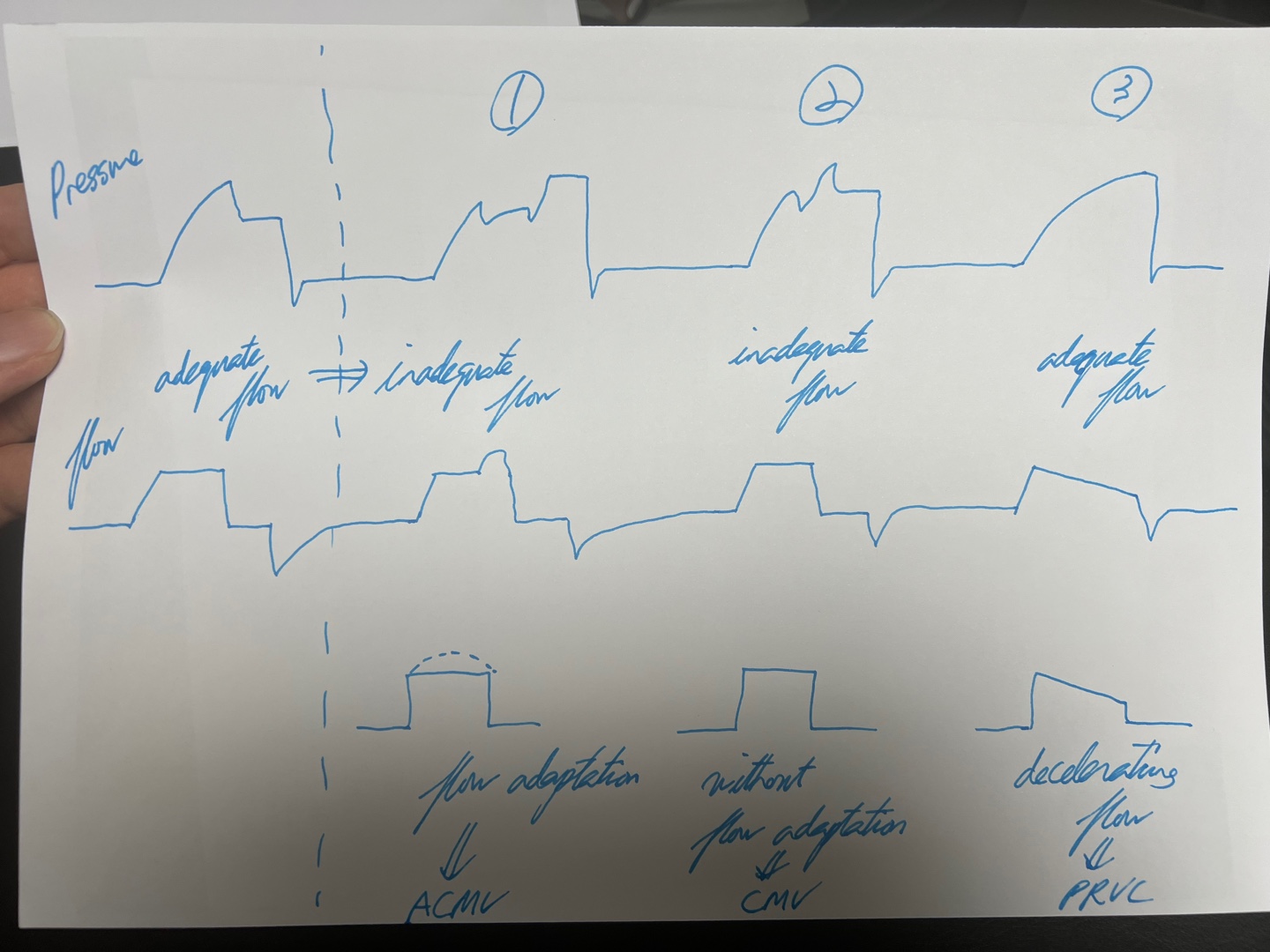
Practically speaking, a significant advantage of Volume Control (VC) ventilation is its ability to allow a single clinician to manage multiple patients simultaneously, especially in scenarios that require interventions like sputum suction, which can decrease minute ventilation (MV). In such situations, VC automatically increases the peak pressure to maintain the predetermined tidal volume (TV), giving clinicians additional flexibility and time to manage other tasks. Conversely, Pressure Control (PC) ventilation maintains a fixed pressure, which does not automatically adjust in response to changes in patient conditions, such as diminished TV due to airway obstruction. This characteristic necessitates a more immediate and direct response from clinical staff to ensure patient safety and effective ventilation.
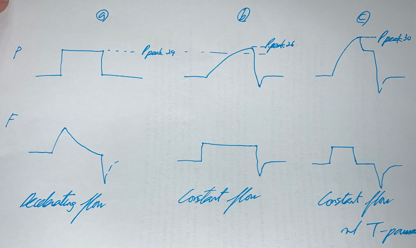
Pressure Control (PC) ventilation offers several significant benefits due to its decelerating flow characteristics. Firstly, it is highly recommended for neonates because it reduces the risk of complications. Secondly, PC ventilation typically results in lower peak inspiratory pressures (PIP), which can minimize the risk of lung injury. The decelerating flow pattern in PC ventilation results in lower PIP because it better accommodates the natural compliance and resistance of the lungs. In contrast, the constant flow pattern in Volume Control (VC) ventilation can lead to higher PIP due to the inability to adjust to varying airway resistance dynamically. Additionally, an increase in mean airway pressure (MAP) can reduce dead space and enhance oxygenation. Furthermore, PC improves patient-ventilator synchrony and reduces the work of breathing (WOB), thereby decreasing the likelihood of the patient 'fighting' the ventilator. This is particularly advantageous as PC allows for flexible adjustment of the inspiration time, contributing to more natural breathing patterns that better meet the dynamic needs of the patient.
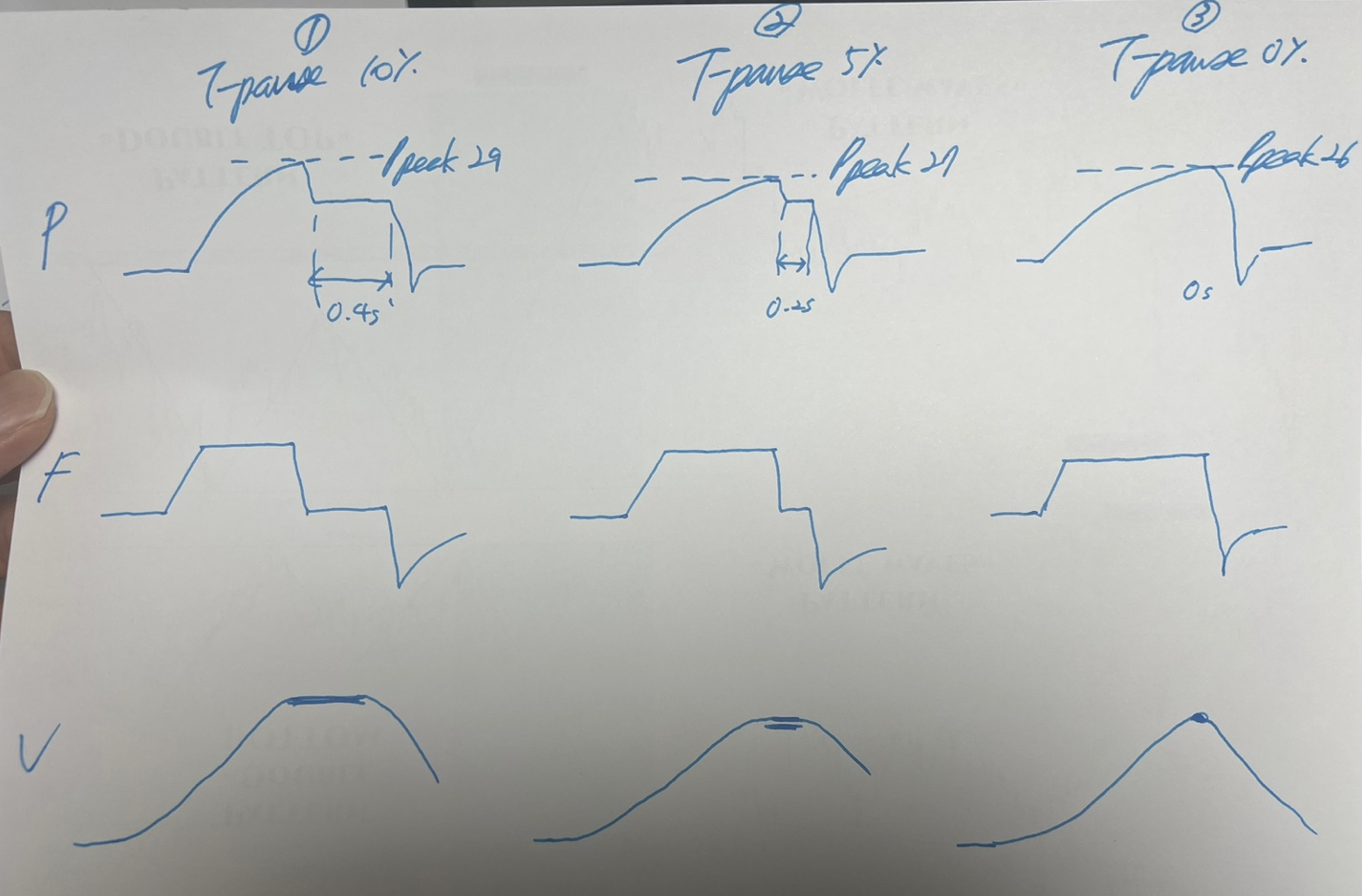
Plateau Pressure: In Volume Control (VC) mode, plateau pressure is not directly visible during regular ventilation cycles. It must be measured using an inspiratory pause, where airflow is briefly halted at the end of inspiration to allow pressures within the lung to equalize, giving a true measure of plateau pressure. Also, during the T-pause, which is the pause time during VC mode, the plateau pressure is estimated effectively due to the cessation of airflow, which allows for pressure equilibration across the pulmonary system, reflecting the pressure exerted by the ventilator against the lung compliance. In Pressure Control (PC) mode, since the ventilator delivers a preset pressure and maintains it throughout the inspiratory phase, the peak pressure is effectively the plateau pressure.
A Hybrid Approach of Volume Control and Pressure Modulation in PRVC
Pressure Regulated Volume Control (PRVC) integrates the precision of Volume Control (VC) with the protective features of Pressure Control (PC), forming a unique and dynamic approach to mechanical ventilation. In this mode, a preset tidal volume is targeted, much like in VC, but the delivery method adapts characteristics of PC by adjusting the inspiratory pressure automatically on a breath-to-breath basis. This adaptability ensures the set volume is delivered with the minimum necessary pressure, enhancing patient safety by reducing the risk of barotrauma. The key settings include not only the tidal volume but also an adjustable inspiratory pressure (capped at an upper limit to prevent lung injury), respiratory rate, inspiratory time, and positive end-expiratory pressure (PEEP), which aids in maintaining alveolar stability and improving oxygenation.
The operational flexibility of PRVC becomes particularly advantageous when managing patients with variable lung mechanics. If a drop in the delivered tidal volume is detected, the system initially applies a volume-type strategy, automatically adjusting to a pressure-type mode if the volume shortfall persists. This ensures the intended tidal volume is maintained even under changing physiological conditions. As the patient's lung mechanics stabilize and tidal volume recovers, the system responsively lowers the peak pressure. This dynamic adjustment not only optimizes gas exchange and lung protection but also minimizes the risk of ventilator-induced lung injuries, making PRVC an essential tool in modern respiratory care, particularly in scenarios where both volume consistency and pressure mitigation are critical. (Additionally, PRVC employs a decelerating flow waveform, similar to PC, enhancing gas exchange and matching ventilation closely to the patient's needs.)
Drawbacks: If the patient's airway resistance increases, the peak pressure cannot rise as rapidly or effectively as in PC mode due to the inherent limitations of PRVC. PRVC adjusts pressure gradually, both increasing and decreasing it slowly. This slower adjustment can lead to delays in reaching the necessary inspiratory pressure during sudden changes in the patient's airway resistance or compliance, making PRVC less responsive in acute situations where rapid pressure adjustments are necessary. Additionally, PRVC's dependence on accurate real-time respiratory data means that sudden changes in the patient's condition or data errors might prevent timely adjustments, potentially leading to inappropriate ventilatory support. Noteworthily, during procedures such as sputum suctioning, the removal of airway obstructions can suddenly reduce airway resistance. PRVC might respond by delivering a higher tidal volume than intended before recalibrating, risking overdistension of the lungs. This potential for increased tidal volume underscores the importance of careful monitoring during such procedures.
Dynamics of Pressure-Driven Ventilation
(A) Understanding PC and PS Mode
Ventilator pressure modes are categorized into controlled and support modes, each tailored to different patient needs. In controlled mode, the ventilator autonomously delivers breaths at preset times and volumes, which is essential for patients who are unconscious or unable to breathe voluntarily. This mode ensures that the patient receives adequate ventilation without relying on their respiratory effort, leading to generally seamless synchrony between the patient and the ventilator due to the absence of patient-initiated breathing efforts.
Conversely, support mode is designed to work in harmony with the patient's own respiratory efforts. It dynamically adjusts variables such as the inspiratory to expiratory (I:E) ratio, inspiratory time, tidal volume, and trigger sensitivity based on the patient's initiated breaths. This mode is particularly beneficial for conscious patients who are capable of voluntary breathing but still require assistance to maintain adequate ventilation. However, achieving synchrony in support mode can be challenging, as the ventilator must finely tune its responses to closely match the timing and intensity of the patient's spontaneous breaths.
Specific considerations arise within these modes, especially concerning Pressure Control (PC) and Pressure Support (PS) ventilation. In PC mode, patients with conscious and voluntary breathing may face synchrony challenges because the fixed pressure delivery might not align perfectly with their natural breathing patterns. This misalignment can lead to discomfort or inefficiency in ventilation support.
In contrast, PS mode often proves more suitable for conscious patients who can initiate breaths. This mode allows for a more natural interaction with the ventilator, which can significantly improve both synchrony and comfort by adapting the ventilation support more closely to the patient's actual respiratory needs. The inspiratory time in PS mode isn't set by the clinician but is instead determined by the patient's inspiratory effort and the cycle-off criteria, typically based on a percentage of peak inspiratory flow. This approach makes the inspiration time more dynamic and patient-driven, reflecting their current respiratory status and contributing to a more personalized ventilation strategy.
Overall, support mode is crucial for patients who are capable of participating in their own breathing yet require assistance to achieve or maintain adequate ventilation. This mode's flexibility helps accommodate individual respiratory patterns and reduces the work of breathing, making it a preferred option for patients in the process of recovering respiratory function.
(B) Adjusting Inspiratory Settings
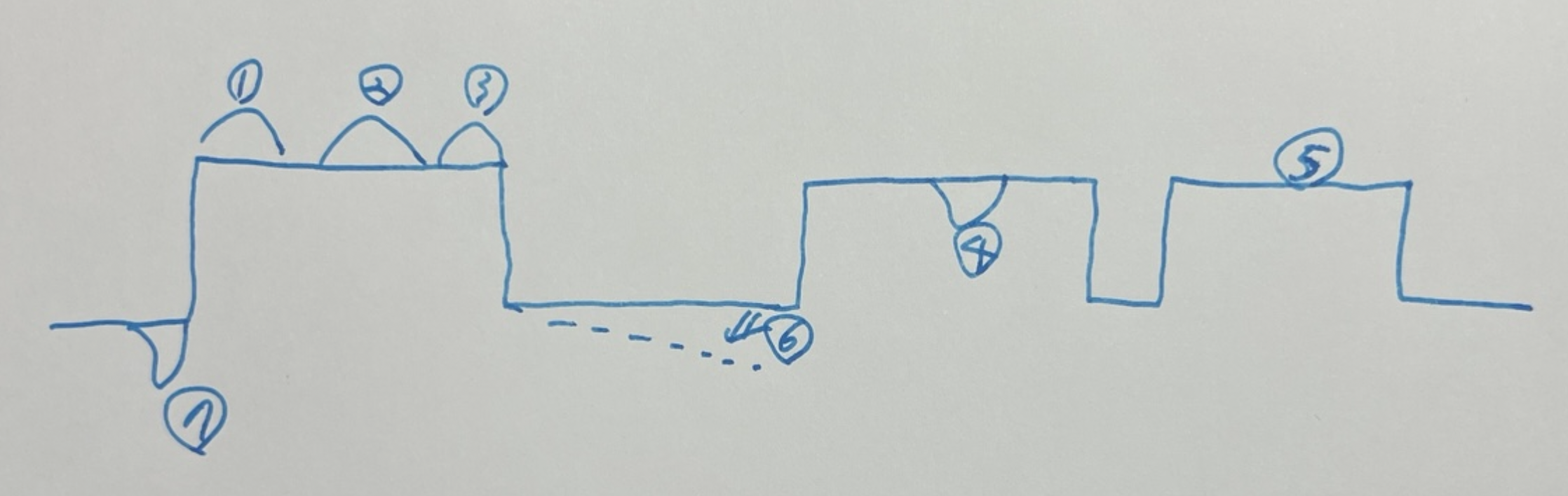
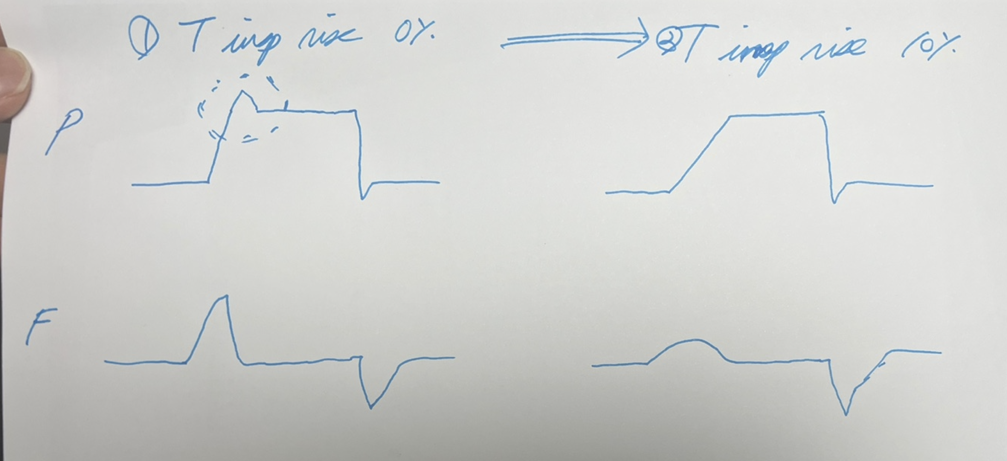
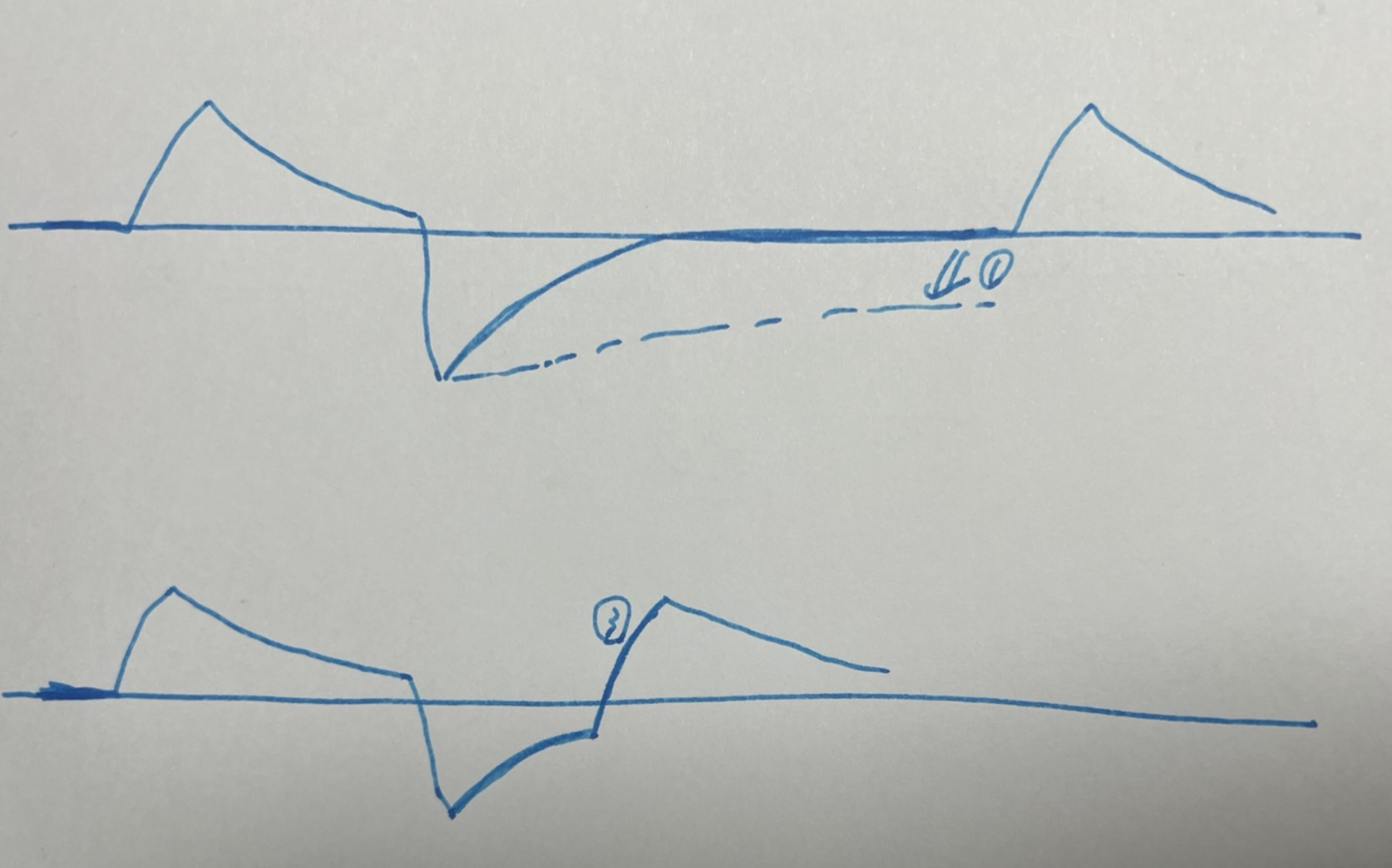
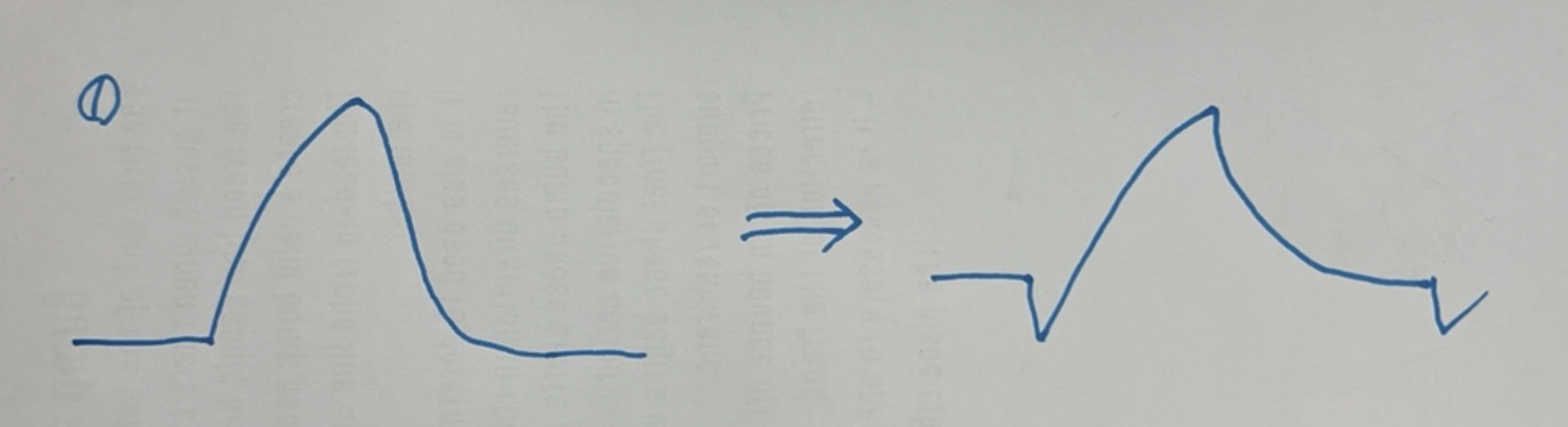
Adjusting inspiratory settings for better outcomes in mechanical ventilation involves meticulous management of the dynamics between Pressure Control (PC) and Pressure Support (PS) ventilation modes. In PC ventilation, manual adjustment of the inspiratory time (Ti) is crucial to maintain patient-ventilator synchrony. Typically, longer Ti settings are well-tolerated during sleep, but adjustments may be necessary when a patient awakens and becomes more active. Changes in the breathing pattern, often observable on the pressure graph as an upward trend at the end of inspiration, indicate the patient's attempt to exhale while the ventilator continues to deliver air. Reducing Ti in these instances helps align the ventilator support with the patient's natural desire to breathe more shallowly or exhale, thereby reducing the risk of patient-ventilator asynchrony, often referred to as "fighting the ventilator."
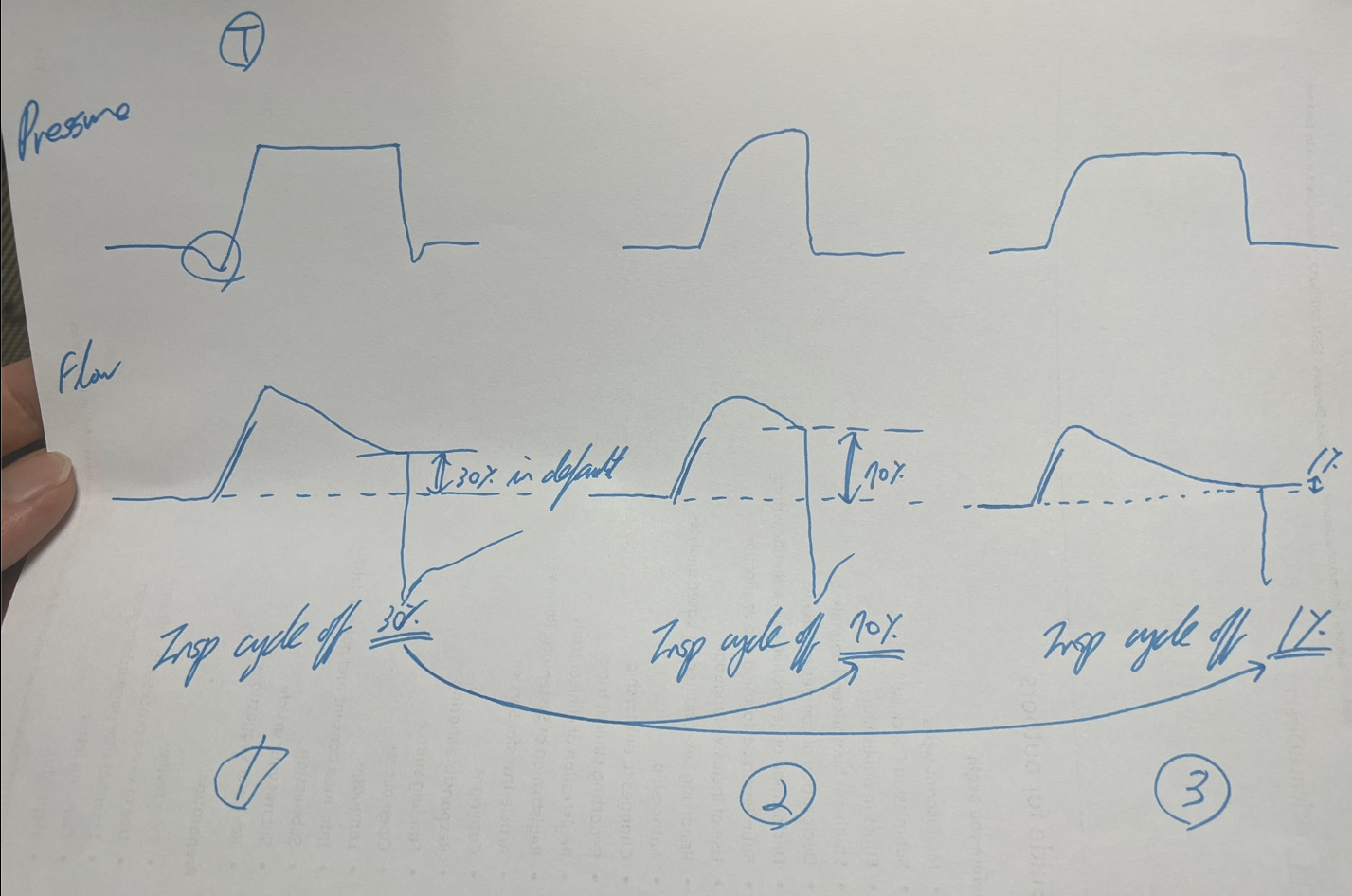
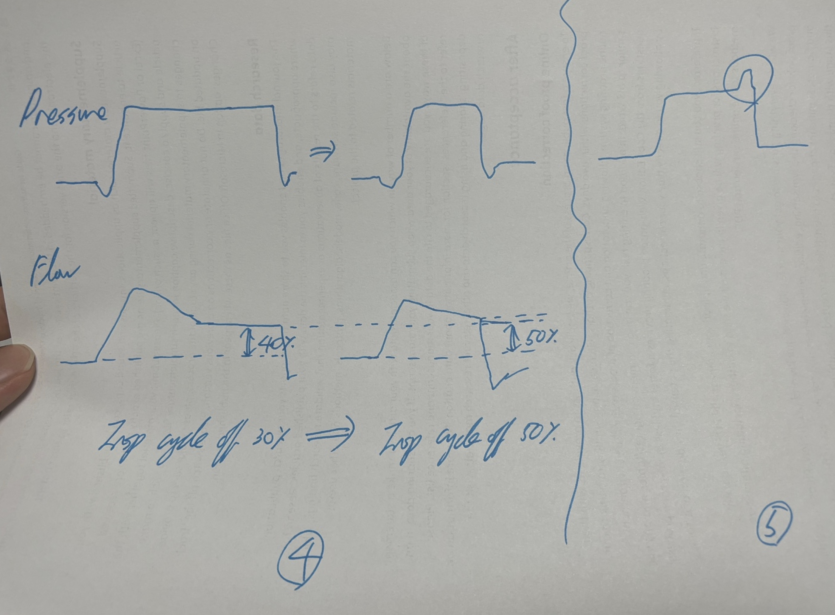
In PS ventilation, the inspiratory cycle-off setting is critical. This setting determines when the ventilator ceases inspiratory pressure support and transitions to expiration, based on a predefined percentage of peak inspiratory flow. Typically, the inspiratory cycle-off is set to terminate inspiration at about 25% of the peak inspiratory flow. Adjustments to this setting are necessary when patients exhibit signs of discomfort or asynchrony, such as trying to exhale while still in the inspiratory phase. Decreasing this percentage to around 15% can allow the ventilator to switch to the expiratory phase sooner, thus reducing the risk of breath stacking and enhancing comfort. This adjustment better synchronizes the ventilator with the patient's breathing efforts, particularly if the patient completes their inhalation quickly or feels that the breaths are too long. Conversely, increasing the cycle-off percentage to around 50% prolongs the time the ventilator provides support during inhalation. This can be beneficial if the patient feels they are not getting enough air before the ventilator cycles off, as it allows more complete inhalation according to the patient's needs.
However, in PS mode, adjusting Ti is not an option since it is inherently designed to be patient-driven. The duration of inspiration is determined by the patient's inspiratory effort and the cycle-off setting, rather than a fixed time set by the clinician. This design emphasizes the supportive nature of PS ventilation, giving patients greater control over their breathing patterns, which is especially vital for those with varying levels of respiratory drive. This approach allows inspiration time to be more dynamic and patient-driven, reflecting their current respiratory needs and efforts, and enhances overall patient comfort and ventilator efficiency.
(C) Understanding and Managing Double Triggering in Mechanical Ventilation
Double triggering is a significant issue in mechanical ventilation, particularly in Pressure Support (PS) and Pressure Control (PC) modes, with a higher occurrence in PS. This phenomenon arises when the ventilator's sensitivity settings fail to align with the patient's actual respiratory demands, or if the inspiratory time set by the device does not synchronize with the patient's natural breathing pattern. Such misalignments can lead to a scenario where a patient initiates a second breath while the first is still being completed, potentially disrupting both patient comfort and the efficiency of the ventilation process.
In PS mode, the ventilator responds to the patient's breathing efforts, and if these efforts trigger the ventilator prematurely during the inspiratory cycle, double triggering may occur. This typically happens if the patient attempts to breathe in again before the machine has completed the cycle, which ideally should transition into expiration. In PC mode, although the ventilators are programmed with preset inspiratory times to mitigate this issue by strictly controlling the breathing cycles, mismatches with the patient's natural respiratory rhythm can still lead to synchronization problems and subsequent double triggering.
To manage and prevent double triggering effectively, it is crucial to ensure that the ventilator settings are meticulously adjusted to the patient's current respiratory status. This includes fine-tuning the sensitivity settings and inspiratory times to better match the patient's natural breathing patterns, thus minimizing the risk of premature initiation of a second breath.
(D) Adjusting Trigger Sensitivity for Improved Patient-Ventilator Synchrony
Effective management of ventilator settings, particularly trigger sensitivity, is essential, especially in the presence of leaks. The default setting for flow trigger sensitivity is typically +2, which detects changes in flow rate to initiate ventilation in response to patient-initiated respiratory efforts. To minimize the risk of auto-triggering due to a leak, it may be necessary to adjust this setting to -2 or lower. Settings in negative values use pressure triggers, which are more precise in detecting actual decreases in pressure, thus ensuring a more accurate response to genuine respiratory efforts and reducing false triggers.
For neonatal patients, who exhibit unique respiratory dynamics, a higher sensitivity setting of +5 may be required. This adjustment ensures that the ventilator can effectively detect the subtle respiratory efforts typical in neonates, which might not activate standard sensitivity settings.
(E) Challenges in ARDS Patients
In scenarios involving patients with Acute Respiratory Distress Syndrome (ARDS), the severely compromised lung function results in rapid exhalation phases, making Pressure Support Ventilation (PSV) unsuitable. PSV depends heavily on the patient's spontaneous breathing, which may be insufficient or unstable in ARDS cases. Consequently, Pressure Control Ventilation (PCV) is generally preferred as it provides better control over the breathing cycle with fixed pressure delivery, aiding in synchronizing ventilation with the patient's respiratory needs.
However, even in PCV, mismatches between the set inspiratory times and the patient's natural breathing rhythm can lead to double triggering — where the ventilator delivers two breaths in rapid succession without allowing for a full exhalation in between. Managing these cases may necessitate clinicians to adjust the trigger sensitivity to make the ventilator less responsive to minor respiratory efforts, increase the volume settings for more complete breaths, or use sedation to moderate the patient's spontaneous breathing efforts, thereby enhancing overall control over ventilation.
(F) Optimizing Pressure Rise Settings
In Pressure Control (PC) mode, rapid increases in pressure at the onset of inspiration can sometimes lead to disruptions in the ventilator's pressure graph, which may appear as abrupt changes or instabilities. Such occurrences can compromise the smooth delivery of ventilation and potentially affect patient comfort. To address this issue, it's essential to adjust the 'T insp rise' setting, which controls the rate at which pressure increases during the inspiratory phase.
Typically, if this setting is at zero (or off), the pressure rise is immediate and steep, leading to what might be perceived as an abrupt start to inspiration. Incrementally adjusting this setting by 5% or 10% allows for a more gradual and controlled pressure increase. This modification helps smooth out the initial pressure transition, thereby stabilizing the pressure graph at the beginning of inspiration. Such adjustments not only enhance the mechanical performance of the ventilator but also improve patient-ventilator synchrony and reduce potential stress on the patient's respiratory system.
(G) "PC above PEEP" and Driving Pressure: Insights from Marcelo B.P. Amato et al. (NEJM, 2015)
In Pressure Control (PC) mode, "PC above PEEP" refers to the pressure set above the baseline Positive End-Expiratory Pressure (PEEP) during the inspiratory phase, and this value is equivalent to the driving pressure. According to the study by Marcelo B.P. Amato et al. (NEJM, 2015), driving pressure (ΔP) is a critical factor associated with survival in patients with acute respiratory distress syndrome (ARDS). The study found that lower driving pressures, achieved by adjusting ventilator settings to avoid increases in peak inspiratory pressure (PIP) while optimizing PEEP, were strongly linked to improved survival rates.
Ventilator Asynchrony
Strategies for Managing Patient-Ventilator Asynchrony
Active Inspiration: Protecting lung integrity is critical, as highlighted by studies such as "Driving Pressure and Survival in the Acute Respiratory Distress Syndrome" by Marcelo B.P. Amato et al. (NEJM, 2015) and "Ventilation with Lower Tidal Volumes as Compared with Traditional Tidal Volumes for Acute Lung Injury and the Acute Respiratory Distress Syndrome" by The Acute Respiratory Distress Syndrome Network (NEJM, 2000). However, strict adherence to these guidelines might lead to insufficient breathing, potentially causing double triggering if patients inhale more than the set tidal volume. To mitigate this, clinicians may consider increasing the tidal volume, adjusting trigger sensitivity, or sedating the patient to decrease spontaneous efforts. Raising the trigger level can enhance ventilator response to patient-initiated breaths, while reducing it helps prevent double triggering. Modifications to ventilator alarm settings, such as the low PEEP alarm, are also often necessary. In Pressure Control (PC) mode, inspiratory time (Ti) is generally set between 0.8 to 1.25 seconds but may be shortened to minimize ventilator conflict. Unlike PC mode, Pressure Support (PS) mode does not allow direct control over Ti, thus incrementally adjusting the "End Inspiration" or "Esens" settings from 30% to 50% can assist in better managing breath termination timing.
Active Expiration: Challenges during expiration, particularly with high Positive End-Expiratory Pressure (PEEP) settings, increase work of breathing (WOB), potentially causing discomfort and leading to non-compliance with ventilation. Shortening the expiratory time in PC mode can effectively address these issues. In PC mode, adjusting the expiratory time primarily involves altering the inspiratory time (Ti) and the respiratory rate (RR), as these settings will indirectly affect how long the expiratory phase lasts. For example, decreasing the Ti from 1.2 seconds to 0.8 seconds and maintaining a consistent respiratory rate will naturally extend the expiratory phase. In Pressure Support (PS) mode, expiratory time adjustment differs since inspiratory time is typically patient-driven. Adjusting the "cycling off" criteria, for instance, setting it to terminate inspiration when the flow decreases to 25% of the peak flow rate, will typically shorten the inspiratory phase and potentially increase the expiratory time.
Managing Leaks: Leaks in Volume Control (VC) mode particularly pose challenges, as they can prevent the ventilator from delivering the set tidal volume accurately. This shortfall in delivered volume can destabilize vital signs and may prompt incorrect ventilator adjustments. "End Inspiration" settings may need to be adjusted upwards (e.g., from 30% to 50%), and "Trigger Pressure" should be set to a less sensitive level (ranging from -10 to -20). Regular checks, such as ensuring proper ET tube cuff pressurization and verifying ventilator integrity with a test lung, are essential for identifying equipment-related issues. If leaks persist, increasing minute ventilation (MV) may temporarily resolve issues until more definitive solutions like reintubation or manual bagging are executed.
Biased Flow: Biased flow maintains a continuous stream of air through the mechanical ventilation system, aiding in keeping airways open and detecting spontaneous breathing efforts. Typically set at 2 liters per minute, biased flow comprises a significant part of the total ventilation volume. For example, out of a total of 9 liters, 7 liters are ventilator-delivered, and 2 liters are biased flow. An active inhalation of 1.6 liters (or 80% of the biased flow) by a patient indicates effective inspiration. For smaller or weaker patients, increasing the biased flow (from 2L to 3L or 4L) ensures even minimal efforts are recognized, thus easing their breathing work. However, too high a setting may induce auto-triggering, where minor disturbances are mistakenly interpreted as breathing attempts. Adjusting sensitivity settings can help mitigate auto-triggering, ensuring the ventilator supports only genuine respiratory efforts.
Improving Patient-Ventilator Synchrony Through Neurally Adjusted Ventilatory Assist (NAVA)
Neurally Adjusted Ventilatory Assist (NAVA) represents a progressive form of mechanical ventilation that optimizes the synchronization between the ventilator and the patient by leveraging the electrical activity of the diaphragm (EAdi). This technology allows the ventilator to respond dynamically to the patient's breathing needs, ensuring that assistance is provided in direct correlation with their respiratory effort. This method not only enhances comfort but also aligns precisely with the patient's natural respiratory drive, crucial for those who can breathe spontaneously but require additional support due to conditions like respiratory failure or challenges in weaning from mechanical support.
The functionality of NAVA hinges on the continuous monitoring of Edi, which acts as the primary trigger for ventilatory assistance. When a patient initiates a breath, the resulting electrical activity of the diaphragm prompts the ventilator to deliver pressure proportionate to this signal, ceasing as the signal diminishes. This responsive system adapts to the patient's breathing needs in real-time, offering a level of support directly correlated to their respiratory muscle effort, thereby mitigating the risks of over- or under-ventilation and enhancing comfort.
The principle of NAVA lies in its ability to detect and utilize the diaphragm's electrical signals as the direct driver for ventilatory assistance. The ventilator adjusts its support based on real-time changes in EAdi, providing a tailored respiratory aid that prevents the common pitfalls of conventional ventilation, such as asynchrony or mismatched timing and intensity of support. This responsiveness to the patient's own respiratory signals makes NAVA particularly advantageous for patients with varying respiratory drive and those susceptible to discomfort with traditional mechanical ventilation methods. However, the efficacy of NAVA can be compromised in patients with conditions that impede the generation or detection of accurate EAdi signals, such as severe diaphragmatic dysfunction, certain neuromuscular disorders, or obstructive esophageal pathologies that prevent proper catheter placement.
NAVA is particularly beneficial in conditions like Acute Respiratory Distress Syndrome (ARDS) in adults and Respiratory Distress Syndrome (RDS) in neonates. It's also indicated in cases of pulmonary hypertension and scenarios requiring detailed assessment of respiratory activity, such as in central hypoventilation syndrome. However, its application is limited by conditions that affect the diaphragm's ability to generate reliable Edi signals, such as neuromuscular disorders, severe diaphragmatic dysfunction, or esophageal anomalies, which might impede the placement or function of the necessary esophageal catheter.
Setting up a NAVA system requires meticulous initial adjustments to ensure optimal patient support. These settings include establishing the NAVA level, which is calculated by the formula NAVA level x (Edi max - Edi min) + PEEP, and determining the trigger sensitivity. The chosen NAVA level, expressed in cmH2OμV, should aim for a target Edi range of 5-20 μV, adjusted based on observed Edi max values to either enhance or reduce ventilatory support.
Clinically, NAVA has shown to significantly improve patient-ventilator synchrony, reducing the risks associated with mechanical ventilation such as ventilator-induced lung injury. By supporting the natural breathing pattern of the patient rather than overriding it, NAVA facilitates a more physiological form of respiratory support, which can lead to better outcomes in the weaning process and overall patient comfort. Its capability to adjust support based on the patient's immediate respiratory muscle output distinguishes it from other assisted modes like Pressure Support Ventilation (PSV), which may not accurately align support with patient effort.
The real-world application of NAVA, especially in complex clinical scenarios, underscores its significant benefits. Studies have documented improved outcomes in diverse patient populations, including adults with acute respiratory conditions and neonates experiencing respiratory distress (Beck et al., 2009; Breatnach et al., 2010). The ability to maintain effective ventilation despite challenges such as air leaks — common in both invasive and non-invasive forms of ventilation — further demonstrates NAVA's robustness (Beck et al., 2009). Its adaptability extends to non-invasive applications, where it can be used with nasal prongs or masks, allowing for a smoother transition from invasive to non-invasive support and potentially reducing the need for higher pressures typically required in conventional ventilation settings (Makker et al., 2020).
Shah, S. D., & Anjum, F. (2024). Neurally Adjusted Ventilatory Assist (NAVA). In StatPearls [Internet]. Treasure Island (FL): StatPearls Publishing. Retrieved from https://www.ncbi.nlm.nih.gov/books/NBK572111/
Beck, J., Reilly, M., Grasselli, G., Mirabella, L., Slutsky, A. S., Dunn, M. S., & Sinderby, C. (2009). Patient-ventilator interaction during neurally adjusted ventilatory assist in low birth weight infants. Pediatric Research, 65(6), 663-668. https://doi.org/10.1203/PDR.0b013e31819e72ab
Breatnach, C., Conlon, N. P., Stack, M., Healy, M., O'Hare, B. P. (2010). A prospective crossover comparison of neurally adjusted ventilatory assist and pressure-support ventilation in a pediatric and neonatal intensive care unit population. Pediatric Critical Care Medicine, 11(1), 7-11. https://doi.org/10.1097/PCC.0b013e3181b0630f
Makker, K., Cortez, J., Jha, K., Shah, S., Nandula, P., Lowrie, D., Smotherman, C., Gautam, S., & Hudak, M. L. (2020). Comparison of extubation success using noninvasive positive pressure ventilation (NIPPV) versus noninvasive neurally adjusted ventilatory assist (NI-NAVA). Journal of Perinatology, 40(8), 1202-1210. https://doi.org/10.1038/s41372-019-0578-4
Spontaneous Breathing and Ventilator Weaning
A Comparative Analysis of Ventilation Modes for Patients with Spontaneous Breathing
When considering the various modes of mechanical ventilation with spontaneous patient breathing — Spontaneous Timed (ST), BiPAP (Bilevel Positive Airway Pressure), BiVent/APRV (Airway Pressure Release Ventilation), Volume Support (VS), Pressure Support (PS), and CPAP (Continuous Positive Airway Pressure) — it's essential to understand both their operational characteristics and the freedom they afford to patients. Each mode requires specific parameters to be set, ensuring optimal ventilation and patient comfort during respiratory support:
ST: EPAP/IPAP, RR, FiO2, and Ti
BiPAP: EPAP/IPAP, RR, FiO2 (, and Ti as the maximum duration of inspiration allowed by the ventilator)
PS: FiO2, PEEP, and PS above PEEP
CPAP: FiO2, CPAP, and trigger sensitivity
In understanding these modes, it's crucial to note that PS mode with 'PS above PEEP' set at zero essentially functions as CPAP, offering continuous positive airway pressure without additional support during inspiration. This equivalence underscores the versatility of PS mode, adapting its function based on settings to meet patient needs. BiPAP, on the other hand, provides variable pressure support during both inhalation and exhalation, offering enhanced ventilation assistance compared to CPAP or PS alone. However, despite its efficacy, BiPAP may feel more restrictive to patients due to its dual-pressure levels. Conversely, CPAP, whether delivered independently or through PS mode, offers continuous support with less complexity, potentially affording patients a greater sense of freedom in their breathing.
When considering freedom to breathe, PS mode stands out as it allows patients to initiate breaths spontaneously and breathe at their own pace. This mode synchronizes with the patient's respiratory effort, providing additional support when needed, while still allowing for variability in breathing rates and patterns. ST mode, while offering partial ventilatory support, imposes fixed intervals for mandatory breaths, which may feel somewhat restrictive compared to the flexibility of PS mode. BiPAP, with its dual-pressure levels, offers tailored support during both inspiration and expiration but may feel more constraining due to its preset parameters. CPAP, whether provided independently or through PS mode, offers continuous positive airway pressure without additional support during inspiration, providing a stable environment for breathing but potentially lacking the adaptability of PS mode.
BiVent/APRV is notable for its innovative ventilation strategy that emphasizes spontaneous breathing across the entire respiratory cycle. This mode operates by maintaining a high baseline airway pressure to optimize oxygenation and alveolar recruitment, while periodically dropping to a lower pressure to allow for CO2 elimination without disrupting the patient's natural breathing attempts. The high pressure phase supports the alveoli continuously, which is critical for patients experiencing severe respiratory distress. In contrast, the brief, controlled lower pressure phase acts like a sigh, aiding in more effective CO2 removal. This mode's ability to allow spontaneous breathing throughout its cycle offers a significant improvement in patient comfort compared to more traditional, restrictive methods.
Volume Support (VS), on the other hand, provides a blend of controlled and supportive ventilation, ideal for patients who are capable of initiating breaths but require assistance in achieving consistent tidal volumes due to varying respiratory muscle strength or lung compliance. Once a patient initiates a breath in VS mode, the ventilator adjusts the pressure dynamically to deliver a predetermined tidal volume. This adaptability ensures adequate ventilation while permitting the patient to control the timing and frequency of breaths, thereby reducing fatigue and promoting a more natural breathing pattern. Unlike modes such as Pressure Support (PS) or BiPAP, VS not only supports the breath initiated by the patient but also guarantees the delivery of a specific volume, adjusting pressure as needed on a breath-by-breath basis to maintain consistent minute ventilation.
Ventilation Settings and Their Role in Effective Weaning
Weaning patients from mechanical ventilation is a critical step in their recovery, marking the transition from artificial support back to natural breathing patterns. Typically, humans breathe using negative pressure, where the diaphragm creates a vacuum that draws air into the lungs. In contrast, mechanical ventilation employs positive pressure to push air into the lungs, which can lead to complications such as barotrauma from excessive air pressure and inadequate gas exchange due to low tidal volumes. To mitigate these issues, sedation often facilitates controlled mechanical ventilation with two primary modes: Volume Control (VC), where tidal volume is precisely regulated, and Pressure Control (PC), which adjusts "PC above PEEP" to ensure consistent lung inflation.
As patients stabilize, ventilator settings transition to support modes that allow more spontaneous breathing efforts. Pressure Support (PS) aids each breath initiated by the patient by maintaining "PS above PEEP," while Continuous Positive Airway Pressure (CPAP) maintains a constant pressure to keep the alveoli open, supporting natural lung function but not directly assisting the breathing effort. A notable challenge with support modes like PS is their inability to control the respiratory rate (RR), which can result in apnea if the patient's spontaneous efforts are insufficient.
Transitioning from Controlled Mandatory Ventilation (CMV) to Assisted/Control Mandatory Ventilation (ACMV) is significant, allowing the start of inspiration to be patient-initiated rather than ventilator-initiated, granting more autonomy in the breathing process. For patients requiring intermittent assistance, Synchronized Intermittent Mandatory Ventilation (SIMV) provides mandatory breaths as a backup, set by the SIMV rate, which defines the frequency of controlled breathing. Crucially, if there is an absence of spontaneous patient breathing, the system reverts from ACMV to CMV, ensuring continuous ventilation. However, between controlled breaths, PS can be activated to provide necessary support.
Moreover, transitioning from PS to CPAP involves shifting the control from "PS above PEEP" to a mode where only PEEP is provided, allowing patients under CPAP to utilize negative pressure for breathing. Significantly, if the inspiration strength in PS is set to zero, it effectively transitions the operation to CPAP, emphasizing passive support through maintained PEEP without additional pressure support. This phase is critical as it encourages patients to engage their respiratory muscles more actively, vital for successful weaning.
Assessing Readiness for Ventilator Weaning Using RSBI and P 0.1: To determine if a patient is ready for weaning from mechanical ventilation, two key measures are often evaluated: the Rapid Shallow Breathing Index (RSBI) and the P 0.1 or Occlusion Pressure. The RSBI is calculated by dividing the respiratory rate (RR) by the expiratory tidal volume (VTe) measured in liters. An RSBI value less than 105 breaths per minute per liter is considered indicative of a patient's readiness for weaning. This index, measured during a spontaneous breathing trial, helps assess the patient's workload of breathing, providing a quantitative basis for evaluating their ability to breathe independently.
Additionally, the P 0.1, which is the negative pressure exerted by the patient in the first 100 milliseconds of an occluded airway, is another crucial measure. A P 0.1 value between 1 to 2 cm H2O suggests a lower respiratory drive, which can indicate that the patient may be ready for weaning. This measure provides insight into the patient's respiratory effort and capacity to maintain adequate breathing without ventilatory support. Both the RSBI and P0.1 are essential in providing a comprehensive assessment of a patient's potential to successfully transition off mechanical ventilation.
Rapid Shallow Breathing Index (RSBI) Calculator
Predicts the success of weaning from mechanical ventilation. An RSBI ≤ 105 breaths/min/L is considered an indicator of readiness for weaning.
RSBI = f / VT
RSBI Calculator
Factors to Consider for Weaning from Mechanical Ventilation
Successful weaning from mechanical ventilation requires a holistic evaluation of the patient's clinical status. While the Rapid Shallow Breathing Index (RSBI) is a valuable predictor, it should be considered alongside other critical factors to ensure the patient is ready for spontaneous breathing without mechanical support.
RSBI ≤ 105 breaths/min/L
An RSBI of 105 or less is widely accepted as an indicator that the patient may be ready for weaning. This threshold suggests that the patient is likely to tolerate spontaneous breathing effectively.
Hemodynamic Stability
The patient should exhibit stable blood pressure and heart rate without the need for high doses of vasopressors. Hemodynamic stability indicates that the cardiovascular system can support the increased workload associated with independent breathing.
Adequate Oxygenation
A PaO₂/FiO₂ ratio greater than 150–200 with minimal positive end-expiratory pressure (PEEP ≤ 5 cm H₂O) demonstrates sufficient gas exchange capacity. This level of oxygenation suggests the lungs can function adequately without extensive ventilatory support.
Optimal Mental Status
The patient should be awake, alert, and cooperative. Adequate cognitive function ensures that the patient can manage airway protective reflexes and participate in the weaning process.
Effective Airway Protection
A strong cough and the ability to clear secretions are essential. The patient should manage secretions without excessive assistance to reduce the risk of aspiration and respiratory complications.
Manageable Secretion Burden
Secretions should be minimal and easily handled without frequent suctioning. Excessive secretions can obstruct airways and impede successful weaning.
Absence of Significant Respiratory Acidosis
Blood gas analyses should indicate stable respiratory function without significant acidosis (PaCO₂ near the normal range). This stability suggests the patient can maintain adequate ventilation independently.
Minimal Ventilatory Support Requirements
The patient should require low levels of ventilatory support, indicating readiness to breathe without assistance. Parameters such as low PEEP and low inspiratory pressures are favorable signs.
Nutritional and Metabolic Stability
Adequate nutritional status and electrolyte balance support muscle strength and endurance, which are crucial for sustained spontaneous breathing.
Absence of Infection or Fever
The patient should be free from active infections or fever, as these conditions can increase metabolic demands and respiratory workload, potentially hindering the weaning process.
Psychological Readiness
Emotional and psychological factors can impact respiratory function. The patient should be assessed for anxiety or other psychological conditions that might affect weaning success.
A comprehensive assessment involving a multidisciplinary team is essential to evaluate these factors thoroughly. Each patient's unique clinical context should guide the decision-making process, ensuring that weaning is conducted safely and effectively with close monitoring for any signs of distress or failure.
RSBI: N/A
SIMV Rate and Breath Cycle Time Across Clinical Scenarios
I. Foundational terminology
SIMV rate – number of SIMV intervals initiated each minute.
Breath cycle time – programmed duration of one mandatory breath (inspiration + expiration).
SIMV interval – the span between successive synchronization windows; mathematically
\( \text{SIMV interval} = \dfrac{60\ \text{s}}{\text{SIMV rate}} \).
Synchronization window – the first portion of each SIMV interval, lasting exactly one breath cycle time, during which a mandatory breath may be synchronized with patient effort.
90 % threshold – the safety mark at \(0.9 \times \text{breath cycle time}\); absence of effort by this point mandates a time‑triggered breath.
Pressure support (PS) – flow‑cycled assistance given to spontaneous efforts that occur after the single mandatory breath within the current interval.
II. Delivery algorithm
The synchronization window opens at the onset of each SIMV interval and spans one breath cycle time.
If an effort arises before the 90 % threshold, a synchronized mandatory inflation is issued.
If no effort occurs by the threshold, a time‑triggered mandatory breath is delivered.
Only one mandatory breath is permitted per interval; subsequent efforts before the next interval receive PS.
No residual free period exists; the ventilator begins a new interval immediately after 3 s.
Scenario A — spontaneous effort present
Elapsed time (s)
Action
Reason
0.5
Synchronized mandatory breath
Effort detected early.
Scenario B — no spontaneous effort
Elapsed time (s)
Action
Reason
2.7
Time‑triggered mandatory breath
Delivered at the threshold; interval ends at 3 s.
Clinical pearl: High SIMV rates eliminate free periods, making the mode functionally similar to a fully synchronized controlled mode; inspiratory time and flow must be adjusted to avert insufficient tidal volumes.
IV. Physiological and operational rationale
Minute‑ventilation assurance vs muscle preservation – one mandatory breath per interval guarantees baseline ventilation, while free periods (when present) enable diaphragm recruitment.
Asynchrony mitigation – restricting synchronization to a defined window reduces double‑trigger and early‑cycle dyssynchrony.
Progressive weaning – decreasing SIMV rate enlarges free periods, progressively shifting work of breathing to the patient.
A brief peak at the very start of inspiration indicates
inspiratory pressure overshoot. The pattern appears when the set
inspiratory flow or rise-time exceeds the capacity of the lung–airway
system (low compliance, high resistance, or a very short rise-time).
Not an asynchrony by itself; considered a machine-related artifact.
Mitigation: lengthen rise-time or reduce peak inspiratory flow.
Effect of inspiratory rise-time on early pressure overshoot and patient comfort.
(0) Tinsp rise 5 % — factory default; balanced patient comfort.
(1) Tinsp rise 0 % — instantaneous rise; marked early-pressure overshoot (“fighting”).
(2) Tinsp rise 10 % — slower ramp; overshoot minimized, mean airway pressure (Pmean) and delivered tidal volume (VT) fall slightly while synchrony improves.
Inspiratory rise time is the interval from the onset of inspiration to the moment peak inspiratory pressure is reached (some ventilators use a flow-based definition). It is set as a fraction of the total respiratory cycle; with respiratory rate RR = 15 breaths·min–1 (Tcycle = 4 s):
\[
T_{\text{rise}} \;=\; f_{\text{rise}}\times T_{\text{cycle}} \;=\; f_{\text{rise}}\times \frac{60}{RR}.
\]
Thus a 10 % setting yields \(T_{\text{rise}} = 0.10 \times 4\text{ s} = 0.4\text{ s}\). Lengthening Tinsp rise reduces overshoot and dyssynchrony at the cost of a modest drop in VT and Pmean.
Mid-inspiratory upward spike
A sudden transient rise after inspiration begins most commonly signifies a
cough, hiccup, or transient glottic closure.
Pressure climbs momentarily because the airway is briefly obstructed.
Falls under expiratory flow limitation / protective reflexes.
Not classified as “fighting.”
Late-inspiratory upward bulge
Upward inflection just before inspiratory flow should cease identifies a
premature expiratory effort — an example of
expiratory (cycling) asynchrony or
“early cycling / flow-termination mismatch.”
Recognised as patient–ventilator fighting because the patient
attempts to end inspiration while the ventilator continues to deliver flow.
A dip below the pressure baseline during inspiration represents a
patient inspiratory effort stronger than delivered flow.
The airway pressure falls because flow or tidal volume is inadequate.
Categorised as flow starvation / pressure-drop asynchrony.
Perceived as “fighting”; resolved by increasing peak flow or choosing a
mode with demand-adapted flow.
Post-inspiratory double peak (“stacked breaths”)
If spontaneous effort persists after the ventilator cycles off,
a second mandatory breath may be triggered, producing two consecutive breaths.
This phenomenon denotes double triggering (also called
breath stacking).
Classic trigger asynchrony; a clear manifestation of “fighting.”
Progressive pressure decay during exhalation
When measured PEEP drifts below the set PEEP and the expiratory pressure
slope falls slowly toward zero, the usual cause is an air-leak
(circuit, cuff, or chest drain).
Identified as a ventilator-circuit problem, not fighting.
Corrective action: locate and seal the leak or reinflate the tracheal-tube cuff.
Pre-trigger drop in PEEP before inspiration
A noticeable fall below PEEP immediately before the inspiratory valve opens
reveals a vigorous negative-pressure trigger effort.
When excessive, the event is termed excessive negative-pressure trigger
and may cause patient discomfort.
Still a trigger asynchrony; regarded as “fighting” when frequent or pronounced.
Are all of the above “patient-ventilator fighting” ?
The informal phrase “fighting the ventilator” broadly includes any
patient–ventilator asynchrony that induces distress, ineffective ventilation,
or abnormal work of breathing.
Accurate classification remains crucial: ventilator settings (flow, rise-time,
cycling criterion) must be optimised, leaks eliminated, and reflex causes
treated before every anomaly is labelled as “fighting.”
Pattern No.
Main cause
Category
1
Rise-time too short / high flow
Machine artifact or Fighting
2
Cough / glottic reflex
Physiologic reflex
3
Premature expiratory effort
Fighting
4
Flow starvation
Fighting
5
Double triggering
Fighting
6
Air-leak
Circuit fault
7
Excessive negative trigger
Fighting
Troubleshooting checklist
Inspect the circuit for leaks, condensate, and cuff pressure.
Match inspiratory flow to demand; increase peak flow or prolong rise-time if negative scoops occur.
Adjust cycling criteria in pressure-support modes (e.g., raise the %-peak-flow threshold) to prevent premature expiratory effort.
Evaluate sedation and analgesia if coughs, double triggering, or vigorous efforts continue.
Consider proportional-assist or NAVA when conventional modes cannot achieve synchrony.
Written on June 7, 2025
Interpreting ventilator FLOW-waveform anomalies (Written June 7, 2025)
Typical findings and corrected explanations
Prolonged expiratory tail (“slow rise”)
In a normal passive breath, expiratory flow decays exponentially to
baseline within ≈1 s. Obstructive diseases (COPD, asthma) lengthen the time
constant, producing a gently sloping tail that fails to reach zero before
the next inspiration.
Represents expiratory flow limitation and air-trapping.
Predisposes to intrinsic PEEP (auto-PEEP) and CO2 retention.
Incomplete exhalation before the next breath
When inspiratory flow begins while expiratory flow is still positive,
residual gas remains in the lungs.
Direct sign of auto-PEEP; flow never touches the zero line.
Total PEEP (measured during expiratory hold) exceeds the set
PEEP by ≥2 cmH2O.
Mid-expiratory inspiratory spike
A brief reversal of flow halfway through exhalation reflects a
premature spontaneous inspiratory effort that prematurely
retriggers the ventilator.
Classified as trigger asynchrony (“fighting”).
Resolve by reducing trigger sensitivity or lengthening expiratory time.
Plateaued low-flow segment (“flow-plateau”)
A long stretch of nearly constant, low expiratory flow followed by an
abrupt drop suggests dynamic airway collapse or a
pursed-lip–breathing effect.
Common in severe emphysema; titrate extrinsic PEEP to splint airways.
Saw-tooth oscillations on the expiratory curve
Fine, regular undulations superimposed on the descending limb usually stem
from secretions or condensate causing intermittent,
partial obstruction.
Clear the airway or drain circuit water to restore a smooth trace.
How flow anomalies signal CO2 retention
Flow waveform: persistent expiratory flow at the onset of
inspiration or mid-expiratory reversals implies trapped gas and increased
dead-space ventilation.
Minute ventilation (V̇E): when V̇E falls
and PaCO2 (or end-tidal CO2) rises, alveolar
ventilation is inadequate despite apparent tidal volumes.
Total PEEP vs. set PEEP: an elevated measured PEEP during
expiratory hold (> set PEEP) quantifies intrinsic PEEP
and correlates with CO2 retention severity.
How do patterns 1–4 actually differ?
No.
Waveform detail
Does flow reach zero ?
Any flow reversal ?
Shape cue
Principal mechanism
Main consequence
1
Prolonged tail gradually decays
X (approaches but above)
X
Gentle slope >1 s
High time-constant lungs (COPD/asthma)
Progressive air-trapping, rising auto-PEEP
2
New breath starts while flow still positive
X (clear gap from baseline)
X
Sharp “cut-off” by next inspiration
Expiratory time too short
Established auto-PEEP >2 cmH2O above set
3
Brief mid-expiratory spike upward
—
✔ (negative→positive)
Narrow peak in exhalation limb
Premature patient effort retriggers breath
Trigger asynchrony (“fighting”)
4
Long, flat low-flow plateau then sudden drop
X (plateau above zero)
X
“Shelf” at ≈0.1–0.2 L·s-1
Dynamic small-airway collapse (emphysema)
Air-trapping despite adequate expir-time
Why 1 ≠ 2
Pattern 1 shows a gradual decay that merely suggests impending
air-trapping; pattern 2 proves the trap has already occurred because inspiration
interrupts active exhalation. Total-PEEP measurement confirms the difference.
Why 3 ≠ 4
Pattern 3 is defined by flow reversal—a spike crossing zero as the
patient tries to inhale; pattern 4 never reverses but instead stalls at a low
flow owing to airway collapse. The former is solved by trigger tuning,
the latter by judicious extrinsic PEEP.
Troubleshooting checklist
Lengthen expiratory time (↓ RR or adjust I:E ratio) to allow complete exhalation.
Apply extrinsic PEEP judiciously to counteract dynamic airway collapse without aggravating hyperinflation.
Suction and humidify to eliminate saw-tooth patterns caused by secretions.
Optimise trigger settings (flow or pressure sensitivity, trigger delay) to prevent premature inspiratory spikes.
Monitor PaCO2, end-tidal CO2, and total PEEP; adjust ventilation strategy when values climb.
Written on June 7, 2025
Interpreting ventilator VOLUME-waveform anomalies
Normal symmetry:
Inspired tidal volume (VTi) matches exhaled tidal
volume (VTe) within ≈10 %. The
volume-time trace returns to baseline before the next breath, forming
uniform rectangles on the scalar display.
Typical findings and corrected explanations
VTe < VTi (“volume loss”)
A persistent gap between inspired and expired volume indicates gas
escaping the system.
Cuff or circuit leak is the usual culprit.
Waveform cue: descending limb slopes smoothly but ends below the
zero-line target; baseline drifts downward over successive breaths.
Baseline not reached between breaths (“volume stacking”)
The expiratory limb fails to return to zero before the next inspiration,
causing the trace to “ride” progressively higher.
Represents incomplete exhalation / auto-PEEP.
Often accompanies obstructive flow patterns; VTe may equal
VTi yet the baseline elevation betrays gas trapping.
Step-like double plateau (“breath stacking”)
Two mandatory breaths delivered in rapid succession without an expiratory
phase create a two-step inspiratory limb and a single, larger expiratory
descent.
Caused by double triggering (trigger asynchrony).
Net VTi nearly doubles; VTe eventually matches,
but oversize volumes risk barotrauma.
Abrupt volume collapse (“disconnection”)
Both inspiratory and expiratory tracings plummet to zero suddenly and
remain flat.
Signifies circuit disconnection or massive leak.
Immediate alarm and reconnection required.
Serrated descent (“secretions artifact”)
Fine oscillations decorate the expiratory limb, mirroring saw-tooth flow
patterns.
Attributed to airway secretions or water condensation.
Suctioning or circuit drainage resolves the serrations.
Perform an expiratory hold to quantify total PEEP when baseline fails to return to zero.
Adjust trigger sensitivity or sedation level to stop breath stacking.
Reconnect or replace circuit immediately if a flat-line appears.
Suction airway and drain humidifier to remove serrated artifacts.
Written on June 7, 2025
Flow adaptation in volume-targeted ventilation: ACMV, CMV, and PRVC
I. Conceptual framework
Volume-controlled (VC) breaths deliver a preset tidal volume by using a square-wave inspiratory flow. Depending on whether the ventilator allows the patient to draw additional (“adaptive”) flow above the square baseline—or replaces the baseline with a decelerating pattern—the breath is classified as assist/control mandatory ventilation (ACMV), controlled mechanical ventilation (CMV), or pressure-regulated volume control (PRVC).
Flow adaptation denotes the ventilator’s ability to sense negative deflection in airway pressure or inspiratory effort and deliver extra flow above the programmed constant value, thereby meeting the patient’s instantaneous demand without altering the target tidal volume.
II. Mode-specific mechanics
ACMV — VC with flow adaptation
When the patient initiates a stronger inspiratory effort during a square-wave VC breath, the ventilator permits a transient upward inflection in the flow waveform. This additional flow maintains patient comfort, shortens inspiratory muscle work, and prevents the pressure–time curve from dipping below baseline. Trigger sensitivity must remain high enough to capture spontaneous effort yet low enough to avoid auto-cycling.
CMV — VC without flow adaptation
In CMV the flow waveform is rigidly constant; the ventilator ignores any further negative pressure generated by the patient after the first trigger. The square-wave remains flat, so dyssynchrony may occur if inspiratory demand exceeds the programmed flow. This mode is suitable for deeply sedated or pharmacologically paralysed patients in whom spontaneous effort is undesirable (e.g., during acute lung recruitment or intracranial pressure control).
PRVC — VC with decelerating flow
PRVC targets a set tidal volume but controls pressure rather than flow. The ventilator measures the compliance on each breath, then computes the minimal inspiratory pressure needed to achieve the volume while imposing a decelerating flow pattern. Peak inspiratory pressure is automatically adjusted—typically within a ±3 cm H2O window—to reach the volume goal with the lowest feasible pressure.
When a ventilator lacks a dedicated PRVC mode, selecting a decelerating flow option under VC partially reproduces PRVC’s gentler pressure profile; however, pressure is no longer actively regulated and peak variations may grow if compliance changes abruptly.
III. Pressure-Regulated Volume Control (PRVC)
PRVC is a closed-loop “hybrid” mode that guarantees a set tidal volume (VT) while automatically choosing the lowest possible inspiratory pressure on every breath.
The ventilator delivers a decelerating flow waveform—similar to pressure control (PC)—which spreads the flow early and tapers it late, lowering peak inspiratory pressure (Ppeak) compared with square-flow volume control (VC).
How the algorithm works
Starts with a test breath, measures dynamic compliance, then calculates the minimum pressure above PEEP needed to hit the target VT.
On each subsequent breath it compares the measured exhaled VT with the target and tweaks the driving pressure in small steps (≈ ±3 cm H2O).
Regulation-pressure limit alarm. If VT (e.g., 500 mL) still falls short, the ventilator keeps stepping the pressure up until either the target is met or the operator-set maximum pressure limit is reached—then an alarm (“regulation pressure limited”) announces that higher pressure is forbidden and VT may drop.
Why PRVC behaves like VC and PC
VC
PRVC
PC
Volume target
Volume target with adaptive pressure
Pressure target
Square flow
Decelerating flow → lower Ppeak
Decelerating flow
Upper-pressure alarm terminates the breath early,
often yielding a small VT
Controller raises pressure to avoid lost VT
yet stays below the limit
Pressure is fixed; VT falls if compliance worsens
Operator-set variables
Target VT (primary goal)
Respiratory rate (RR) — pairs with VT to determine minute ventilation
Inspiratory time / I:E ratio
PEEP
Maximum pressure limit (e.g., 30–35 cm H2O); set high enough to allow adaptation yet low enough to remain lung-protective
VC: watch delivered VT; if the high-pressure limit aborts the breath, VT drops.
PC: watch VT; pressure is fixed, so stiff lungs yield smaller volumes.
PRVC: watch both:
Ppeak — a gradual climb signals worsening compliance or resistance.
Exhaled VT — a sudden fall means the pressure limit has been hit or spontaneous effort has waned.
Strengths
Decelerating flow and breath-by-breath pressure minimization lower Ppeak and plateau pressure.
Maintains target VT even when compliance changes, avoiding the low-volume alarms common in PC and the pressure spikes of square-flow VC.
Limitations & watch-outs
Hidden compliance deterioration: the ventilator quietly ratchets pressure up until it hits the limit; clinical decline may be missed unless Ppeak is trended.
Slow to sudden load changes: stepwise 3 cm H2O adjustments may lag rapid events (bronchospasm, tubing kink).
Spontaneous over-assistance: strong efforts raise VT; the algorithm answers by lowering pressure, so the next passive breath may be under-supported.
Post-obstruction overshoot: after suctioning or secretion clearance, the previously high pressure can overshoot volume before the next recalibration—set tight volume alarms during airway procedures.
Sensor accuracy: leaks or water in the circuit can feed bad data to the controller, causing inappropriate pressure changes.
Clinical tip. Set the maximum pressure limit high enough (but safe) so PRVC can “do its job” in stiff lungs—commonly 5–7 cm H2O above your plateau-pressure goal. Then trend both Ppeak and exhaled VT to catch rising pressures or falling volumes early.
III. Pressure-regulated volume control (PRVC) - Old Version
PRVC is a closed-loop hybrid mode designed to deliver a clinician-selected tidal volume while capping airway pressure on every breath. The ventilator begins with a test breath, measures dynamic compliance, and then calculates the minimum inspiratory pressure required to achieve the target volume using a decelerating flow waveform. On subsequent breaths it compares the exhaled tidal volume against the set point and automatically adjusts the inspiratory pressure—typically in ±3 cm H2O increments—until the volume target is met. Because flow decelerates, most of the breath is spent near the calculated peak pressure, yielding a pressure–time profile that resembles pressure control (PC), yet the controlling objective remains volume delivery, classifying PRVC as a volume-controlled strategy at its core.
The principal motivation for PRVC is to fuse the lung-protective advantages of PC (lower peak and plateau pressures, decelerating flow) with the metabolic certainty of a guaranteed tidal volume. This makes the mode attractive for patients whose compliance fluctuates rapidly—such as those with early acute respiratory distress syndrome, evolving pulmonary oedema, or post-operative atelectasis—where conventional VC risks pressure spikes and pure PC risks under-ventilation. However, PRVC can up-titrate inspiratory pressure to its safety ceiling if compliance deteriorates, potentially masking clinical decline; conversely, vigorous spontaneous effort may cause the algorithm to undershoot delivered volume.
Operator-controlled inputs are the target tidal volume, respiratory rate, inspiratory time (or I:E ratio), PEEP, and a maximum allowable pressure limit. The ventilator responds by modulating inspiratory pressure—and therefore peak flow—breath-by-breath, while maintaining the decelerating flow waveform typical of PC. The result is a mode that “looks and feels” like pressure control at the bedside, yet behaves as volume control under the hood, continuously trading small pressure adjustments for precise volume assurance.
Operator-set variables
Target tidal volume (VT) ― primary goal the algorithm strives to deliver.
Respiratory rate (RR) ― pairs with VT to determine minute ventilation.
Inspiratory time or I:E ratio ― defines the duration available for pressure delivery and flow deceleration.
Positive end-expiratory pressure (PEEP) ― baseline pressure on which the inspiratory pressure is added.
Maximum pressure limit ― safety ceiling (often 30–35 cm H2O); the ventilator will not exceed this value when auto-adjusting.
Trigger sensitivity & cycling criteria ― determine patient–ventilator synchrony but do not alter the adaptive algorithm.
Why PRVC behaves like volume control
Guaranteed volume. Breath-by-breath adjustments continue until the measured exhaled VT matches the set target.
Minute-ventilation predictability. Because VT and RR are fixed inputs, minute ventilation remains stable despite compliance changes.
Alarms and data display. The ventilator still tracks “volume-delivered” errors similarly to conventional VC.
Why PRVC mimics pressure control
Decelerating flow pattern. Flow peaks early and tapers, creating a pressure–time curve indistinguishable from PC.
Inspiratory pressure targeting. The machine sets and adjusts an inspiratory pressure above PEEP rather than a fixed flow.
Lower peak pressures. Auto-adjustment aims for the minimal pressure that achieves the target volume, often reducing PIP compared with square-flow VC.
Limitations and watch-outs
Hidden compliance deterioration. The ventilator silently raises inspiratory pressure toward the safety ceiling as the lung stiffens. Because the rise is incremental, clinical decline may remain unnoticed until the preset limit is reached and tidal volume abruptly falls.
Sluggish response to sudden load changes. PRVC modifies inspiratory pressure in discrete steps (≈ ±3 cm H2O per breath).
When airway resistance or compliance shifts abruptly—such as during bronchospasm, kinking, or chest-wall splinting—the algorithm cannot elevate pressure as fast as pure pressure control (PC).
The delayed rise can produce brief hypoventilation, elevated work of breathing, and alarm activation.
Spontaneous over-assistance. Vigorous patient effort inflates exhaled volume above the target.
The controller reacts by lowering inspiratory pressure; when the effort subsides, the breath that follows may be under-supported, creating a pendulum of hypo- and hyper-ventilation.
Risk of inadvertent volutrauma after obstruction relief. During procedures such as tracheobronchial suction, the sudden removal of secretions markedly reduces airway resistance.
The previously calculated pressure—now too high for the improved condition—can overshoot the target, delivering a larger tidal volume before the next breath permits recalibration.
Close bedside monitoring and temporary volume alarms are advised whenever airways are manipulated.
Dependence on accurate real-time data. Sensor drift, water condensation, or circuit leaks may feed erroneous pressure–volume information into the controller, prompting inappropriate pressure adjustments that persist until the fault is detected.
IV. Comparative summary
Feature
ACMV (VC + adaptive flow)
CMV (VC + fixed flow)
PRVC (pressure-regulated VC)
Primary control variable
Volume
Volume
Pressure (for volume goal)
Flow waveform
Square with upward spikes when patient inhales harder
Square, no deviation
Decelerating from an initial peak
Peak inspiratory pressure (PIP)
May rise if extra flow is large
Fixed; rises only with resistance/compliance change
Auto-adjusted breath-to-breath; generally lower than ACMV/CMV
Best clinical fit
Spontaneously breathing, lightly sedated patients
Paralysed or deeply sedated patients
Patients with variable compliance who need lung-protective volumes
Risk of dyssynchrony
Low
High if demand exceeds flow
Low (variable pressure + flow)
V. Practical bedside considerations
Trigger and cycle settings. In ACMV, ensure sensitive inspiratory triggers and appropriate cycle criteria to harness adaptive flow without auto-triggering.
Alarm limits. Because adaptive or decelerating patterns alter peak flow, flow and pressure alarms must be widened slightly to prevent nuisance alerts while retaining safety.
Monitoring. Continuous evaluation of PIP, tidal variability, and patient effort (e.g., pressure-time product or diaphragm ultrasound) confirms that the chosen mode meets lung-protective and comfort goals.
VI. Key takeaways
Flow adaptation distinguishes ACMV from conventional CMV by allowing demand-driven flow augmentation during square-wave volume breaths.
PRVC replaces the square-wave with a decelerating flow, automatically titrating inspiratory pressure to deliver the set volume at the lowest feasible PIP.
When dedicated PRVC is unavailable, selecting a decelerating-flow VC breath offers partial pressure relief but lacks breath-to-breath pressure regulation.
Mode selection should weigh patient effort, lung mechanics, and the need for precise volume targeting against the potential for pressure-induced injury.
Written on June 7, 2025
Triggering mechanics in assisted ventilation: Pressure- vs Flow-Triggering
A mechanical breath begins when the ventilator detects patient effort through either a pressure trigger (drop below baseline circuit pressure) or a flow trigger (deflection of a continuous bias flow). Trigger sensitivity determines how much patient effort is required—less negative pressure or smaller flow reduction signifies a more sensitive trigger.
I. Pressure triggering
With pressure triggering the ventilator monitors circuit pressure relative to set PEEP. Inspiration is delivered when airway pressure falls by at least the trigger threshold \(\Delta P_{\text{trig}}\).
Sensitivity scale. Typical adult thresholds range from −1 to −5 cm H2O; a setting of −2 is relatively sensitive, whereas −10 is markedly insensitive and increases inspiratory workload.
PEEP interaction. If PEEP = 7 cm H2O and the trigger is −10, the patient must generate an airway pressure of −3 cm H2O (7 − 10) to initiate a breath—often unattainable in respiratory fatigue.
Clinical caveat. Excessive sensitivity (< −1 cm H2O) may promote auto-triggering from cardiogenic oscillations or circuit bumping.
Figure. (1) With the trigger threshold set at −10 cm H₂O and PEEP at 7 cm H₂O, the patient-generated drop of −7 cm H₂O is insufficient to initiate a breath. (2) Reducing the threshold to −2 cm H₂O renders the ventilator sensitive enough to recognise the same effort and deliver inspiration.
II. Flow triggering
Flow triggering employs a constant bias flow—commonly 2 L·min−1 in adults, 0.5 L·min−1 in paediatrics—and recognises inspiration when a portion of that flow is diverted into the patient.
Over-sensitive values (e.g., \(S \ge 8\)) may auto-trigger during leak, patient repositioning, or water condensation movement, precipitating breath stacking.
III. Comparative considerations
Work of breathing. Flow triggering generally halves trigger effort compared with pressure triggering because the patient alters flow rather than generating extra negative pressure.
Leak tolerance. Large leaks diminish net flow change, making flow triggering unreliable; pressure triggering may be preferred when unavoidable leaks exist (e.g., uncuffed tracheostomy, neonatal circuits).
Noise immunity. Pressure triggering is less vulnerable to circuit vibration but more prone to missed efforts if set too insensitive.
IV. Practical adjustment algorithm
Start with flow triggering at \(S = 4\)–5 (≈ 40–50 % bias-flow drop) in adults; observe pressure–time curve for early dips indicating effort.
If missed efforts appear, increment sensitivity by 1 step and re-evaluate; if auto-triggering occurs, decrement by 1–2 steps or switch to pressure trigger.
For pressure triggering, begin at −2 cm H2O; titrate toward −1 if effort remains high or toward −4 if auto-triggering persists.
Always reassess after position change, secretion clearance, or introduction of a circuit leak.
V. Key points
Trigger sensitivity must balance patient comfort against inadvertent auto-cycles.
Flow triggering reduces inspiratory workload but is leak- and motion-sensitive.
Pressure triggering remains dependable when leaks are unavoidable, provided the threshold is not set excessively negative.
Written on June 7, 2025
T-pause and inspiratory time (Ti): timing mechanics in VC and PC
In volume-controlled (VC) ventilation, the clinician fixes the tidal volume and allows the ventilator to generate a square (constant) inspiratory flow to deliver that volume within the preset inspiratory time. Because the flow trace is flat, the entire inspiratory period is actively filling the lungs unless an explicit inspiratory pause (T-pause) is inserted at the end of inspiration. When a pause is added—commonly 10 % of the total cycle time—the active-flow window shortens while the delivered volume remains unchanged; the ventilator therefore compensates by increasing instantaneous flow, which in turn elevates peak inspiratory pressure (Ppeak). Minute ventilation (ĖV) under VC follows the direct proportionality ĖV = VT × RR, so any adjustment to respiratory rate (RR) or tidal volume (VT) alters global carbon-dioxide clearance, whereas changes in pause fraction mainly influence alveolar pressure dynamics and airway stress.
Pressure-controlled (PC) ventilation, by contrast, targets a constant airway pressure rather than a fixed volume. The inspiratory flow automatically decelerates as the lungs fill, reaching near-zero toward the end of inspiration; this intrinsic taper means there is effectively no need for an additional T-pause. For a given compliance, PC can achieve the same tidal volume as VC while maintaining a lower Ppeak, thereby reducing the risk of barotrauma in patients with stiff or injured lungs. Using the illustrative VC settings RR = 15 breaths·min-1 (Tcycle = 4 s), I:E = 1:2 (ideal inspiratory window ≈ 1.33 s), and T-pause = 10 % (0.40 s), the active-flow time contracts to 0.93 s; reproducing the same volume in that shorter span demands a steeper flow ramp and raises Ppeak. In PC mode the flow would simply taper earlier without an imposed pause, keeping airway pressures lower while preserving the delivered volume—provided that inspiratory time is long enough to reach the pressure target.
➤ In pressure-controlled ventilation there is no separate T-pause. Once the set driving pressure (Pcontrol above PEEP) is reached, flow passively decelerates to near-zero, so the plateau pressure you observe is simply Ppeak = PEEP + Pcontrol. Any sudden change that increases airway resistance or decreases compliance—such as retained secretions—will cause the delivered tidal volume to fall at the same pressure target. For this reason, vigilant tidal-volume monitoring is essential in PC mode; a downward drift should prompt suctioning, bronchodilation, or adjustment of Pcontrol / Ti to re-establish adequate ventilation.
(1) T-pause 10 % (0.40 s, Ppeak 29 cmH2O); (2) T-pause 5 % (0.20 s, Ppeak 27 cmH2O); (3) T-pause 0 % (0 s, Ppeak 26 cmH2O). All examples use RR 15 breaths·min–1 (cycle time 4 s) and the same tidal volume. As the inspiratory pause lengthens, the active-flow segment of inspiratory time (Ti) contracts, requiring a steeper flow ramp to deliver the preset volume and thus elevating peak inspiratory pressure. A moderate pause remains valuable for plateau-pressure measurement and alveolar recruitment despite the higher Ppeak.
I. Timing building blocks
Total cycle time \(T_{\text{cycle}} = 60 / RR\)
Inspiratory phase partitions into an active-flow segment (\(T_{\mathrm{i,flow}}\)) and an optional T-pause.
Inspiratory time \(T_{\mathrm i}\) (graphical width of the inspiratory flow trace) therefore equals
\[
T_{\mathrm i}=T_{\mathrm{i,flow}}+T\text{-pause}.
\]
Expiratory time \(T_{\mathrm e}=T_{\text{cycle}}-T_{\mathrm i}\).
II. Computing Ti and T-pause in volume control (VC)
Given an operator-selected I:E ratio (\(I:E\)) and pause fraction \(P\) (decimal):
Computes total inspiratory time (Ti), the active-flow segment (Tiflow), and the pause plateau from respiratory rate (RR), a single I:E ratio expressed as 1:E, and a user-defined T-pause percentage.
Ti Calculator
Ti & T-pause: equations and rationale
The total inspiratory time (Ti) sets the window for volume delivery. A brief T-pause raises mean alveolar pressure and allows plateau-pressure measurement, but an excessive pause shortens the active-flow segment and can elevate peak inspiratory pressure or encroach on expiratory time.
IV. Physiological implications of manipulating Ti and T-pause
Gas distribution. Lengthening T-pause raises mean alveolar pressure, aiding alveolar recruitment and static compliance assessment.
Peak pressure. In VC, a longer T-pause forces delivery of the same volume over a shorter \(T_{\mathrm{i,flow}}\), lifting \(P_{\text{peak}}\). In PC, \(P_{\text{peak}}\) stays locked, but VT may fall if Ti is too short.
CO2 clearance. Effective minute ventilation obeys \(\dot V_{\mathrm E}=V_{\mathrm T}\times RR\); trimming Ti (especially \(T_{\mathrm{i,flow}}\)) without compensatory RR may elevate PaCO2.
Auto-PEEP risk. Prolonging Ti or T-pause at high RR shortens expiratory time, predisposing to air-trapping in obstructive physiology.
V. Bedside adjustment workflow
Choose baseline RR and I:E to assure \(T_{\mathrm e}\geq 2\tau\) (twice the patient’s expiratory time constant).
Introduce T-pause ≤10 % when accurate plateau pressure or alveolar recruitment is required.
After adding pause, re-check \(P_{\text{peak}}\) (VC) or delivered VT (PC). If unsafe, either lower VT, extend \(T_{\text{cycle}}\), or reduce P.
Monitor arterial gases; adjust RR if PaCO2 rises due to reduced \(T_{\mathrm{i,flow}}\).
VI. Key takeaways ✏️
Ti comprises an active-flow segment plus T-pause; only the active segment determines instantaneous flow and \(P_{\text{peak}}\).
In VC, increasing T-pause elevates \(P_{\text{peak}}\) by squeezing flow into a shorter window; in PC, pressure stays fixed but volume may drop.
Balanced timing preserves expiratory time, maintains minute ventilation, and avoids barotrauma or auto-PEEP.
Written on June 7, 2025
Written on June 7, 2025
PS and CPAP modes
Pressure-support (PS) and continuous positive airway pressure (CPAP) represent the least mandatory forms of mechanical assistance. These modes permit the patient to determine respiratory rate and—with appropriate settings—optimize comfort while maintaining adequate gas exchange. A safety net is provided by an apnea back-up algorithm that automatically delivers pressure-controlled (PC) breaths if spontaneous effort ceases.
Apnea back-up ventilation
When no spontaneous trigger is detected within the pre-set apnea time (factory default 20 s but adjustable, e.g. 15 s in the alarm profile), the ventilator converts to a PC back-up pattern until patient effort resumes.
Back-up pressure above PEEP (ΔP): clinician-selected driving pressure.
Back-up respiratory rate (RR): typically 10–15 breaths·min-1.
Inspiratory:expiratory (I:E) ratio: often 1:2; ensures adequate expiratory time.
Alarm behaviour: if the required ΔP to attain the target tidal volume approaches the operator-defined pressure limit, a “regulation pressure limited” alarm is annunciated, yet the ventilator strives to preserve ventilation without breaching the ceiling.
Even during back-up PC, the pressure limit should be set high enough to enable protective tidal volumes but low enough to avoid barotrauma.
CPAP
Setting pressure support above PEEP to 0 cm H2O converts the circuit to pure CPAP. The ventilator then provides only the selected PEEP and oxygen concentration, relying entirely on the patient’s inspiratory effort for tidal ventilation. Back-up PC remains available should apnea occur.
Pressure-support (PS)
Core adjustable variables
Pressure support above PEEP (ΔP): primary determinant of tidal volume.
PEEP: baseline pressure.
FiO2: oxygen fraction.
Tinsp rise: time from trigger to attainment of target pressure (comfort parameter).
Trigger sensitivity: flow- or pressure-based threshold initiating inspiration.
Inspiratory cycle-off (End inspiration): flow threshold (%) at which inspiration terminates and exhalation begins.
Inspiratory cycle-off and timing mechanics
PS lacks an I:E ratio; instead, inspiratory cycle-off governs inspiratory time (TI) relative to total breath duration (Ttot). The ventilator switches to exhalation when inspiratory flow decays to a defined fraction of its peak.
Default threshold: 30 % of peak inspiratory flow.
Raising threshold (≥ 40 %): earlier cycling, shorter TI, smaller tidal volume; useful when late-inspiratory “fighting” or double triggering is observed.
Lowering threshold (< 30 %): prolonged TI, larger tidal volume; may improve ventilation in restrictive lungs but risks air trapping if expiratory time becomes insufficient.
General use; adjust as compliance or demand changes
1 %
Very late termination; longest TI
Extreme restrictive physiology when larger tidal volume is required
Leakage and resistance considerations
Circuit leaks (e.g., reduced cuff pressure) sustain elevated flow throughout inspiration, preventing decay to the cycle-off threshold and unintentionally prolonging TI. When compensation raises the effective threshold above the set value, the cycle-off percentage should be increased to restore timely exhalation.
Managing inspiratory “fighting”
Increase the inspiratory cycle-off threshold (e.g., from 30 % to 40–50 %) to allow earlier cycling.
Shorten Tinsp rise when flow demand is high; lengthen it when overshoot occurs.
Verify trigger sensitivity to prevent delayed inspiration.
Inspiratory cycle-off effects in PS mode.
(1) Default cycle-off 30 % of peak flow.
(2) Cycle-off 70 % → earlier switch to exhalation.
(3) Cycle-off 1 % → prolonged inspiration, larger tidal volume.
(4) Cycle-off set to 30 % but cuff pressure falls; compensation elevates effective threshold (≈40 %), lengthening inspiration—raise the setting above 40 % to restore timing.
(5) Late-inspiratory “fighting” produces an end-inspiratory pressure spike; increasing cycle-off shortens TI and resolves the dyssynchrony.
Clinical summary
PS and CPAP permit spontaneous breathing with adjustable pressure support and PEEP, while an apnea timer safeguards against hypoventilation via PC back-up.
Inspiratory cycle-off replaces I:E ratio in PS; meticulous adjustment optimizes comfort, prevents air trapping, and avoids late-inspiratory dyssynchrony.
Pressure limits in back-up PC and PS should balance lung protection with tidal-volume adequacy; both ΔP and delivered volumes require continuous monitoring.
Written on June 8, 2025
PRVC algorithmic software framework: breath-by-breath pressure regulation with decelerating flow
Pressure-regulated volume control (PRVC) is a hybrid mode of mechanical ventilation that combines the advantages of volume control (VC) and pressure control (PC). A target tidal volume (VT) is delivered while the ventilator continuously adapts the inspiratory pressure on a breath-by-breath basis, using a decelerating (ramp-down) flow pattern. This strategy aims to minimize peak inspiratory pressure (PIP) and improve patient–ventilator synchrony.
Foundational principles
Flow patterns during inspiration
Constant (square-wave) flow (typical of traditional VC): Delivers a fixed flow until the set VT is reached. To achieve the same VT as PC, VC generally requires a higher instantaneous PIP because gas must be driven into the lungs at a fixed rate irrespective of changing compliance or resistance. When an inspiratory pause time (Tpause) is added to VC, flow stops while the airway remains occluded, increasing both alveolar pressure and measured PIP even further.
Decelerating flow (used in PRVC and PC): Starts with a high peak flow and progressively tapers, distributing gas more evenly and lowering PIP for an identical VT. The early, high-flow phase quickly meets patient demand, improving comfort and synchrony.
Figure. Ventilator pressure (P) and flow (F) waveforms under three inspiratory strategies. (a) PRVC with a decelerating flow pattern delivers the target tidal volume with a peak inspiratory pressure (PIP) of 24 cm H₂O; (b) volume-controlled ventilation (VC) using a constant, square-wave flow requires a higher PIP of 26 cm H₂O; (c) adding an inspiratory pause to constant-flow VC increases PIP further to 30 cm H₂O.
Breath-to-breath pressure regulation algorithm
PRVC employs an adaptive software loop:
Initialization – “learning” breath: The ventilator often delivers a VC-like test breath at a modest flow to measure the patient’s compliance and airway resistance.
Pressure estimate: Using the measured VT and peak/plateau pressures, the microprocessor calculates the minimum inspiratory pressure (Pinsp) projected to deliver the set VT on the next breath.
Delivery as a pressure-controlled breath: The subsequent breath is given in PC format at the computed Pinsp with a decelerating flow waveform.
Continuous adaptation: After each breath, the delivered VT is compared with the target. If VT is lower (or higher) than desired, Pinsp is incremented or decremented—typically by 1–3 cmH2O—on the following breath, constrained by an upper safety limit Pmax.
This closed-loop approach preserves volume assurance while always seeking the lowest effective pressure.
The decelerating flow profile front-loads flow, so alveoli fill earlier and the remaining inspiratory time is spent at a lower flow and pressure. As a result, PIP is reduced by 3–10 cmH2O compared with VC at the same VT.
The prolonged end-inspiratory phase raises mean airway pressure (MAP) (the time-averaged pressure over the entire respiratory cycle), creating gentle alveolar recruitment that lowers physiologic dead space and enhances oxygenation without additional barotrauma risk.
Because flow decelerates naturally, patient-triggered efforts are less likely to fight a rigid flow profile, reducing the work of breathing (WOB) and the need for deep sedation or neuromuscular blockade.
Plateau pressure (Pplat)—the static alveolar pressure measured during an inspiratory hold—remains below the lung-protective threshold (≈ 30 cmH2O) more readily than in VC where higher peaks are common, especially if an inspiratory pause is used.
Lower PIP than VC, reducing barotrauma and volutrauma risk. The difference widens further when VC employs an inspiratory pause.
Higher MAP (without a high PIP) improves oxygenation by recruiting atelectatic lung units and reducing ventilation–perfusion mismatch.
Enhanced patient–ventilator synchrony lowers WOB and sedation requirements.
In neonates, PRVC has been associated with fewer ventilator-related complications, including intraventricular hemorrhage.
Important cautions
Rapid, large swings in resistance or compliance (e.g., severe bronchospasm or pulmonary edema) may temporarily outpace the algorithm, risking transient hypoventilation.
Significant circuit or airway leaks (uncuffed tubes, bronchopleural fistula) can lead the ventilator to raise Pinsp inappropriately.
An overly low or overly high Pmax undermines the safety of the algorithm, either limiting tidal volume delivery or eliminating the pressure-limiting advantage.
Written on June 19, 2025
Troubleshooting
Considerations When Using a Jet Nebulizer in Respiratory Therapy
When using a pneumatic jet nebulizer in respiratory therapy, it's crucial to consider its impact on mechanical ventilation parameters. (1) First, introducing a jet nebulizer can significantly increase the flow within the ventilatory circuit, which in turn may inadvertently raise the tidal volume (TV) delivered to the patient. This increase can lead to unexpectedly high lung volumes, risking volutrauma if not closely monitored and adjusted. (2) Additionally, this extra flow can cause a slight increase in airway pressure. While generally mild, this increase requires careful monitoring to prevent potential adverse effects on patients with compromised lung function or those at risk of barotrauma.
(3) Another consideration is the effect on the fraction of inspired oxygen (FiO2). The use of a jet nebulizer can dilute the oxygen concentration within the ventilatory circuit as air is utilized to nebulize the medication, resulting in a reduced FiO2. Adjusting the oxygen settings to compensate for this dilution is essential to ensure that the desired level of oxygenation is maintained. (4) Furthermore, the additional flow and pressure fluctuations introduced by the nebulizer can interfere with the ventilator's sensitivity settings, complicating the initiation of spontaneous breathing by the patient. This may increase the work of breathing and lead to discomfort or fatigue. To mitigate these effects, it may be necessary to adjust the trigger sensitivity settings on the ventilator to lower the threshold required for triggering, thereby reducing the respiratory effort needed from the patient.
Ventilator Troubleshooting Guide
High Airway Pressure (Paw) Alarm: This alarm can be triggered by increased airway resistance or decreased lung compliance. To reduce airway resistance, perform suctioning and administer nebulized treatments. If the issue is related to lung compliance, consider interventions such as inhaled nitric oxide or extracorporeal membrane oxygenation (ECMO) to enhance lung flexibility and functionality.
Decreased Oxygen Saturation: When decreased oxygen saturation is detected, indicated by alarms or monitoring systems, several critical steps must be taken to ensure optimal patient care. Oxygen levels are primarily monitored using SpO2 and arterial oxygen partial pressure (PaO2). Immediate actions include resolving any High Paw Alarm by suctioning and nebulization to decrease airway resistance. It is also vital to thoroughly check the ventilatory circuit for any disconnections or leaks, as these can significantly compromise the oxygen delivery system.
To assess the patient's oxygenation status more comprehensively, performing an arterial blood gas analysis (ABGA) is recommended to check PaO2 levels. Based on these results, adjustments to the fraction of inspired oxygen (FiO2) and positive end-expiratory pressure (PEEP) should be considered. Initially, FiO2 may be increased to deliver more oxygen, especially in acute settings. Concurrently, adjusting PEEP can help improve oxygenation and ensure the patient receives adequate oxygen while preventing potential lung damage.
A practical approach involves starting with higher FiO2 and PEEP settings and then gradually reducing them as the patient's condition stabilizes or improves. For example, beginning with an FiO2 of 100% paired with a PEEP of 12 cm H2O, and methodically lowering both to potentially an FiO2 of 30% and a PEEP of 5 cm H2O as the patient's oxygenation status allows. This systematic and intuitive adjustment process is aligned with the ARDSnet protocol guidelines, which provide extensive tables and further recommendations for managing FiO2 and PEEP in different clinical scenarios.
High Carbon Dioxide Levels (PaCO2): If this alarm activates, first assess whether increased airway resistance is contributing to inadequate CO2 removal. To enhance CO2 clearance, adjust the tidal volume (TV) upwards. Increasing the respiratory rate (RR) can also help by augmenting the overall ventilation. Another strategy is to modify the inspiratory to expiratory ratio (I:E Ratio), which can improve ventilation efficiency. However, care must be taken to ensure that these adjustments do not lead to air trapping, especially in patients with conditions like Chronic Obstructive Pulmonary Disease (COPD).
PEEP High Alarm Due to Filter Obstruction: A 'PEEP High Alarm' in mechanical ventilation typically signals a blockage in the expiratory phase, often due to a clogged filter that impedes the flow of expired air, leading to increased end-expiratory pressure. The crucial step in troubleshooting is to promptly remove the filter to check if it is the source of the obstruction. If removing the filter resolves the alarm and normal ventilation function is restored, this confirms the filter as the culprit. The immediate replacement of the obstructed filter is critical to maintain unimpeded airflow, ensuring the ventilation system operates efficiently and safely.
Management of Expiratory Filters: Expiratory filters are critical in managing airway resistance within mechanical ventilation systems. These filters usually last one to two days, though high-quality, genuine filters can remain effective for up to five days under ideal conditions. Obstructions in these filters are common and can be caused by various factors, including the administration of specific medications such as colistin and coagulants, or due to excessive nebulization. When filter issues are suspected, such as after administering colistin, it is advisable to perform routine checks and ensure timely maintenance or replacement of the filters to maintain optimal ventilation management.
Strategic Use of PEEP in Patients with V/Q Mismatch and Shunting: For patients exhibiting V/Q mismatch or shunting, often caused by lung infiltration as indicated by a chest X-ray, increasing the positive end-expiratory pressure (PEEP) can enhance their condition by improving oxygenation and reducing shunt effects. However, if the PEEP exceeds 10 cm H2O, it may lead to decreased venous return, potentially resulting in hemodynamic instability. In such scenarios, administering an inotrope may be necessary to help maintain or increase blood pressure.
Auto-PEEP Detection and Management (Version I): Auto-PEEP is a significant concern, particularly in patients receiving medications such as colistin or anticoagulants, which can increase the risk of this complication. Monitoring the end-expiratory flow, known as V̇ee on a Servo ventilator, is critical because an increase in V̇ee may indicate the presence of Auto-PEEP, necessitating prompt assessment and intervention to ensure optimal ventilator function and patient safety.
Effective management of Auto-PEEP includes adjusting the inspiratory to expiratory (I:E) ratio, for example, from 1:2 to 1:3. This adjustment extends the expiratory time relative to the inspiratory time, aiming to provide sufficient expiratory time — ideally more than three times the time constant (Tc). This strategy promotes complete exhalation, prevents lung overdistension, optimizes respiratory mechanics, and aids in preventing complications such as air trapping while ensuring efficient CO2 removal. Maintaining the inspiratory time (Ti) within 0.6 to 1.2 seconds, even when altering the I:E ratio, is essential to avoid negative impacts on the patient's breathing pattern.
In scenarios where there is a rapid increase in respiratory rate (RR), continuous monitoring of V̇ee through the "Trends" function on the ventilator is essential. This allows clinicians to observe changes over time and make informed decisions about ventilatory adjustments. Additionally, performing an arterial blood gas analysis (ABGA) is routine to check for CO2 retention and decreased O2 levels, further informing the adjustment process.
Further strategies to manage Auto-PEEP include ensuring clear airways and, if necessary, adjusting the respiratory rate (RR) and tidal volume (TV). Encouraging patients to take deep breaths can help decrease the buildup of intrinsic PEEP and facilitate better lung decompression. Additionally, adjunctive therapies such as nebulization, the administration of steroids, or bronchoscopy may be necessary to address underlying respiratory issues contributing to Auto-PEEP.
Air Trapping Indicators and Management (Version II): Air trapping, commonly seen in conditions like COPD, asthma, or airway edema, manifests through several indicators:
Visual Inspection: The flow graph does not return to zero during expiration, indicating incomplete exhalation.
V̇ee (End-expiratory Flow): A V̇ee greater than or equal to 1 suggests persistent air in the lungs post-expiration.
Arterial Blood Gas Analysis (ABGA): This analysis is essential for checking CO2 levels, with a PaCO2 above 45 mmHg indicating CO2 retention.
Lower Inflection Point (LIP) Changes in PC Mode: A rightward shift in LIP points to increased airway resistance, while a swollen or wider LIP indicates decreased lung compliance. Reassessing the LIP through sputum suction can confirm these conditions.
Monitored PEEP Variations: If the monitored PEEP significantly exceeds the set value, it can lead to decreased cardiac output and unstable blood pressure, indicating severe air trapping. Sometimes, with air trapping, monitored PEEP might significantly exceed the set value (e.g., set at 5 but reads 19 or 20), leading to decreased cardiac output and unstable blood pressure.
Total PEEP: When total PEEP readings exceed set PEEP, it suggests the presence of auto-PEEP, confirming air trapping (e.g., set PEEP at 5 but total reads 6).
Re (Expiratory Resistance): Expiratory resistance, when measured during holds, that falls within the 30-40 range indicates severe CO2 retention and requires urgent intervention. This resistance ranges from normal (5-15) to critical levels (30-40), indicating severe CO2 retention and necessitating immediate attention. While Total PEEP primarily helps in assessing the degree of air trapping and managing auto-PEEP, Re (expiratory resistance) is crucial for diagnosing the extent and cause of airway obstruction and evaluating overall lung mechanics.
Management strategies for air trapping include increasing the expiratory time to allow more complete exhalation, frequent nebulization to reduce airway resistance, and ensuring the expiratory time is at least three times the time constant (Tc) to promote efficient gas exchange and prevent complications from incomplete exhalation.
Air Flow Reductions: In scenarios where there is inspiratory pressure but the airflow drops to zero, urgent assessment and management are crucial to identify and rectify underlying causes. This issue often points to problems with lung compliance or mechanical impediments in the ventilation system. Evaluating lung elasticity is essential, and it's important to ensure that inspiratory pressures are not excessively high, as this could exacerbate lung stiffness and compromise function.
In terms of mechanical causes, obstructions in the endotracheal tube (ET tube) should be checked. Such obstructions can be due to kinking, blockage within the tube, or from the patient biting the tube. Inspecting and, if necessary, replacing the ET tube is crucial. If the patient is biting the tube, using a bite block can prevent occlusion and ensure continuous airflow. Addressing these issues promptly is vital not only to restoring proper airflow but also to preventing potential lung damage from inadequate ventilation.
Additionally, understanding lung compliance through static and dynamic indices can provide insights into lung health and guide appropriate ventilatory support. Static Compliance (Cstat) is calculated from the formula VTe / Pplat - PEEP, where VTe is the exhaled tidal volume, Pplat is the plateau pressure after an inhalation pause, and PEEP is the positive end-expiratory pressure, with normal values ranging from 60 to 100 ml/cm H2O. A value below this range indicates increased lung stiffness. Dynamic Compliance (Cdyn), calculated as VTe / EIP - PEEP, where EIP is the end-inspiratory pressure, typically ranges from 50 to 80 ml/cm H2O. Values below 30 ml/cm H2O suggest severe lung conditions such as Acute Respiratory Distress Syndrome (ARDS). Monitoring these indices helps in fine-tuning ventilatory settings to optimize patient care and outcomes.
Managing ventilator alarms: Paw high and low expiratory minute volume
I. Airway-pressure high (Paw high) alarm
An elevated airway-pressure alarm reflects either increased resistance (secretions, tube kinking, bronchospasm) or diminished compliance (pneumothorax, pulmonary oedema, acute respiratory distress syndrome). A tiered, protocol-driven response preserves lung integrity and forestalls secondary alarms.
1. Immediate safety check
Briefly silence the alarm; keep pressure and flow waveforms visible.
Verify that the upper pressure limit is appropriate (usual setting 35–40 cm H2O); adjust upward only after reversible causes are excluded.
Resolve Paw high promptly; unresolved pressure elevations frequently lead to low minute-volume alarms.
Differentiate resistive issues (secretions, bronchospasm) from compliance loss (pneumothorax, ARDS) to guide targeted therapy.
After leaks are excluded, titrate VT, PIP, and RR incrementally while keeping plateau pressure ≤ 30 cm H2O.
Document alarm events and corrective steps; recurrent patterns often presage evolving pathology before overt decompensation.
Written on June 7, 2025
Q&A
Can BiPAP be delivered via cannula when using the HFT 700 (OmniOx)?
Question: HF was provided through a cannula on the HFT 700 (OmniOx). Can BiPAP also be delivered via cannula, or is a full-face mask or another interface required?
Answer: BiPAP cannot be effectively delivered through the open HFNC cannula used with the HFT 700. A sealed noninvasive ventilation (NIV) interface—such as an oronasal/full-face mask or a helmet—is required to maintain IPAP/EPAP and ensure proper pressure delivery.
1. Why the HFNC cannula cannot provide BiPAP
Open system leaks: HFNC cannulas are intentionally non-sealed; set inspiratory and expiratory pressures dissipate to atmosphere.
Lack of NIV-specific control: The HFT 700 is designed for heated, humidified high-flow oxygen/air, not for dual-level pressure targeting with trigger algorithms and intentional leak ports.
Pressure monitoring limits: Accurate IPAP/EPAP maintenance and alarm management for leaks are not supported in standard HFNC setups.
Oral leak may reduce effectiveness; chin strap may be needed
Helmet NIV
Transparent hood systems
Minimal facial pressure; better tolerance for prolonged use
High flow demand for CO2 clearance; noise; setup complexity
Specialized sealed cannulas (primarily pediatric)
RAM cannula, neonatal nCPAP/BiPAP prongs
Useful in neonates/infants
Limited adult data; pressure transmission may be inconsistent
3. Practical implementation tips
Transition criteria: NIV should be considered when high ΔP is required for CO2 control or when HFNC fails to correct hypercapnia.
Circuit compatibility: Single- or dual-limb circuits and exhalation ports/valves must match the ventilator’s design.
Leak management: Leaks should remain within the device-specific acceptable range, maintained via strap tension and cushion integrity checks.
Combined techniques: Placement of HFNC under a mask for CO2 washout has been described but is not standardized; alarm handling and monitoring become more complex.
4. Conceptual flow (ASCII)
HFNC (HFT 700)
  └─ Heated, humidified high flow via open cannula
       → Mild PEEP (~1–5 cmH2O), CO₂ washout, comfort
       → No stable IPAP/EPAP delivery

BiPAP (NIV-capable ventilator)
  └─ Defined IPAP/EPAP (ΔP) targets
       → Requires sealed interface (mask/helmet)
       → Intentional leak port or expiratory valve for flow/pressure control
In summary, the HFT 700 cannula is unsuitable for BiPAP; a sealed NIV interface is mandatory for effective pressure delivery.
Written on July 23, 2025
Clinical Case Study
Case1: Managing Dyspnea in an ALS Patient with ST Mode Ventilation
Managing a patient with ALS experiencing dyspnea necessitates a nuanced approach to both immediate and long-term respiratory support strategies. An effective initial strategy often includes adjusting the Inspiratory Positive Airway Pressure (IPAP) in Spontaneous/Timed (ST) mode, for example, increasing it from 13 to 15 cm H2O. This adjustment can enhance alveolar ventilation by increasing the tidal volume, potentially alleviating symptoms of dyspnea and reducing the patient's respiratory effort. Such strategic management is essential in addressing progressive neuromuscular conditions like ALS, where muscle weakness can intensify over time, escalating the patient's respiratory workload.
If the patient's dyspnea persists and there is an inclination to remove the ventilator, it might indicate a conflict during inspiration when the patient attempts to exhale. In such scenarios, it is crucial to consider adjusting or increasing the "Cycle" setting of the ST mode from the current 25% gradually upwards. This adjustment can help synchronize the ventilator more closely with the patient's natural breathing cycle, potentially reducing the sensation of fighting the ventilator and improving comfort.
Continuous assessment is crucial to determine if further adjustments or a switch in ventilation mode might offer additional benefits. In cases where adjustments to IPAP alone are insufficient for managing symptoms effectively, or when concerns arise regarding patient comfort and ventilator synchrony, exploring other modes such as BiPAP or CPAP may be warranted.
BiPAP is particularly beneficial due to its capability to independently control both IPAP and EPAP, allowing for customized support during both inhalation and exhalation phases. Unlike ST mode, which primarily focuses on maintaining a minimum number of breaths per minute with less flexibility, BiPAP facilitates dynamic adjustments that can more precisely respond to the patient's varying respiratory needs throughout the day or as their condition changes. This refined approach to respiratory support is especially advantageous in ALS, where patients may experience fluctuating respiratory efforts.
Furthermore, BiPAP can enhance patient-ventilator synchrony by independently and precisely adjusting IPAP and EPAP. This adjustment improves synchrony with the patient's natural breathing cycle, potentially reducing asynchrony and increasing comfort — critical factors for patients who can still initiate breaths but whose respiratory strength may vary. The versatility of BiPAP extends to periods of sleep or varying levels of respiratory muscle fatigue, making it an optimal choice for maintaining comfort and effective ventilation across different states of patient activity and rest.
Pressure Support (PS) mode offers another viable option for patients capable of initiating breaths independently but who require assistance to maintain adequate ventilation. PS mode supports the patient's breathing effort by providing a preset level of pressure support during inhalation, terminated based on the patient's inspiratory flow, thus facilitating a more natural breathing pattern. This mode significantly enhances patient-ventilator synchrony and comfort, particularly beneficial for conscious patients with fluctuating respiratory drive.
Conversely, Continuous Positive Airway Pressure (CPAP) maintains a constant pressure throughout the respiratory cycle. This mode might not suit ALS patients requiring active assistance with inhalation due to muscle weakness. CPAP is generally more appropriate for patients who can maintain adequate spontaneous breathing efforts and primarily need support in keeping their airways open.
Ultimately, the decision to adjust IPAP within ST mode or to transition to another mode such as BiPAP or PS should be driven by ongoing evaluations of the patient's respiratory status, including blood gas analyses and symptom assessment. Regular re-evaluation and close monitoring are essential to ensure that the ventilatory support continues to meet the evolving needs of the ALS patient, striving to achieve an optimal balance of adequate ventilation, patient comfort, and minimal respiratory effort. This comprehensive approach ensures that respiratory management is both effective and adaptable, providing tailored support that evolves with the patient's condition.
Guardian consent obtained for IRB-approved clinical research aimed at disseminating better clinical practices in hemodynamics.
Case2: Tailoring BiPAP Settings for Managing Respiratory Distress with CO2 Retention
In managing respiratory distress in patients using BiPAP ventilation, specific adjustments are essential for those showing signs of hypoventilation and CO2 retention. Typically, these patients demonstrate reduced tidal volumes (Vt) of 150-250 mL, with arterial blood gas (ABGA) analyses indicative of mild respiratory acidosis, typically with a pH slightly below the normal range of 7.35-7.45, and elevated PCO2 slightly above the normal range of 35-45 mmHg. Bicarbonate levels may also be at the upper end of the normal range (22-28 mEq/L), indicating renal compensation. Additionally, an elevated PO2 well above the normal range for room air (75-100 mmHg) suggests the use of supplemental oxygen therapy, which is crucial for managing hypoxemia but requires careful monitoring to avoid complications associated with hyperoxia.
Rationale for Increasing IPAP: An increase in IPAP, for example from 13 to 15 cm H2O, is strategically implemented to enhance alveolar ventilation and improve CO2 clearance. This intervention is essential as it directly increases tidal volume, promoting deeper breaths that not only help in recruiting more alveoli for gas exchange but also effectively eliminate excess CO2.
Reasoning for Lowering Oxygen Supply: Even with stable SpO2 levels above 92%, reducing supplemental oxygen is crucial to prevent oxygen toxicity and hyperoxia, which could suppress respiratory drive — particularly harmful in conditions predisposing to CO2 retention. Adjusting oxygen delivery to maintain SpO2 just above 92% ensures sufficient oxygenation without compromising the patient's inherent respiratory efforts, thereby supporting natural respiratory mechanisms and enhancing overall respiratory function.
Necessity of Manual Adjustment of IPAP: Despite the dynamic capabilities of BiPAP machines to adjust IPAP and EPAP, manual intervention is often required. Automatic adjustments might not always perfectly align with rapidly changing or unique clinical situations due to limitations in preset algorithms. Manually increasing IPAP allows healthcare providers to fine-tune ventilatory settings based on real-time patient responses and specific ventilation goals, ensuring that the therapeutic approach is precisely tailored to achieve optimal outcomes. This level of customization is crucial for effectively managing acute respiratory distress and provides significant advantages over more rigid modes like ST, which are less adaptable to patient-specific needs.
Guardian consent obtained for IRB-approved clinical research aimed at disseminating better clinical practices in hemodynamics.
Case3: Longitudinal Analysis of Ventilator Management in a Patient With Chronic Respiratory Failure
Home Ventilator Application Status
- Chronic CO2 retention and respiratory acidosis
- Compensatory metabolic alkalosis

- December 22, 2023: BiPAP initiated

- December 29, 2023: Due to diaphragmatic dysfunction, home ventilator initiated in SIMV-PS mode
     Tidal Volume (TV): 300–350 mL
     Inspiratory Pressure (Pi): 10–15 cmH2O
     Respiratory Rate (RR): 16 breaths/min

- February 2024: Home ventilator adjusted (SIMV mode)
     Pressure (Pr): 13 cmH2O
     PEEP: 5 cmH2O
     RR: 15 breaths/min
     O2: 1 L/min

- March 25, 2024: Changed to PSV mode
     Measured TV: ~300 mL
     Pressure Support (Pr): 12 cmH2O
     PEEP: 5 cmH2O
     RR: 15 → 14 breaths/min

- November 8, 2024: PSV mode continued
     Measured TV: ~300 mL
     Pr: 12 cmH2O
     PEEP: 5 cmH2O
     RR: 14 breaths/min
The patient has chronic CO2 retention and a compensatory metabolic alkalosis, indicating a long-term respiratory failure scenario. Initial noninvasive management (BiPAP) was followed by a transition to a home ventilator setup due to diaphragmatic dysfunction. Over time, the ventilator mode evolved from SIMV with pressure support to PSV, reflecting changes in clinical strategy and attempts to balance stable support with partial patient-driven ventilation. Ultimately, the patient has maintained stability on a PSV configuration without further reductions in pressure support.
Chronological Overview of Ventilator Management
December 22, 2023 (BiPAP Initiation)
Documented Settings: BiPAP (Bilevel Positive Airway Pressure) initiated, but no exact pressures recorded.
Typical Variables Required:
IPAP (Inspiratory Positive Airway Pressure)
EPAP (Expiratory Positive Airway Pressure)
FiO2 or O2 flow as needed
Commentary: BiPAP provides two distinct pressure levels. At this stage, it was likely chosen to noninvasively support ventilation, reduce CO2 levels, and alleviate work of breathing. Precise IPAP and EPAP values would be necessary to fully reproduce the initial setup. The missing data here—such as exact pressure levels and O2—suggests incomplete information.
December 29, 2023 (Transition to SIMV-PS)
Documented Settings: SIMV-PS mode: TV ~300–350 mL, Pi 10–15 cmH2O, RR 16 (PEEP and exact FiO2/O2 unknown)
Typical Variables Required for SIMV-PS:
For Volume-Controlled SIMV: Set Tidal Volume, RR, FiO2/O2, PEEP
For Pressure-Controlled SIMV: Set Inspiratory Pressure, RR, FiO2/O2, PEEP, and inspiratory time
Pressure Support (PS) level for spontaneous breaths above PEEP
Commentary: Transitioning to SIMV suggests a need for more structured ventilatory support. Some parameters (PEEP, FiO2) are not documented here, making it hard to fully replicate the initial SIMV setup. The mention of Pi (Inspiratory Pressure) suggests a pressure-limited or pressure-supported component for spontaneous breaths.
Commentary: By February, the documentation is more complete: a defined pressure support level (Pr 13 cmH2O) and PEEP (5 cmH2O) are stated, along with RR and O2 flow. This reflects a refinement in the ventilation strategy. The patient is still receiving partial mandatory support (SIMV) along with pressure support for spontaneous breaths. Although O2 is given as 1 L/min, the exact FiO2 remains unreported; still, this information is more sufficient for reproduction compared to December 29, 2023.
March 25, 2024 (PSV Mode Initiation)
Documented Settings: PSV mode: Measured TV ~300 mL, Pr 12 cmH2O, PEEP 5 cmH2O, RR from 15 to 14
Typical Variables Required for PSV:
Pressure Support level (above PEEP)
PEEP
FiO2/O2 flow
The tidal volume and RR are patient-dependent (not “set” but “achieved”)
Commentary: Switching to PSV reduces mandatory breaths, relying on the patient’s inspiratory effort. Pressure Support (12 cmH2O) and PEEP (5 cmH2O) remain key settings. The measured tidal volume (~300 mL) and recorded RR (14) show patient-driven ventilation within supported parameters. Additional variables (exact FiO2, alarm settings) are not specified, but enough information is present to approximate the scenario.
November 8, 2024 (Continued PSV Mode)
Documented Settings: PSV mode: TV ~300 mL, Pr 12 cmH2O, PEEP 5 cmH2O, RR 14
Commentary: No change in support parameters since March 25, 2024. This long-term stability suggests the patient’s condition is neither deteriorating nor significantly improving toward lower support. The ventilator settings remain consistent, likely indicating chronic stable respiratory failure management.
Comparing Noninvasive and Invasive Modes, Including CPAP
BiPAP vs. PSV as Final Steps:
BiPAP (Noninvasive): Often considered for patients who do not require intubation, or as a step down from invasive ventilation to noninvasive support at home. It is suitable as a “final step” in noninvasive respiratory support for stable chronic patients.
PSV (Invasive): Commonly used as a final step in weaning from invasive mechanical ventilation. Once a patient can maintain adequate ventilation and oxygenation on low levels of PSV, clinicians may consider extubation.
What About CPAP?
CPAP (Continuous Positive Airway Pressure): Provides a single constant pressure level. It improves oxygenation by preventing alveolar collapse but does not offer additional inspiratory support.
BiPAP: Offers two pressure levels—IPAP and EPAP. IPAP assists inspiration, while EPAP (similar to PEEP) keeps alveoli open. This dual-level support can augment ventilation and reduce CO2 more effectively than CPAP alone.
Naming and Variables:
BiPAP: "Bi" stands for “Bilevel Positive Airway Pressure,” reflecting the provision of two distinct pressure levels—one for inhalation and one for exhalation.
CPAP: "C" stands for “Continuous Positive Airway Pressure,” signifying a single (continuous) level of pressure throughout breathing cycles.
Required Variables:
CPAP: CPAP pressure level, FiO2
BiPAP: IPAP, EPAP, FiO2 (or O2 flow)
Weaning Criteria and Advanced Indices
Weaning from mechanical ventilation—whether invasive (via PSV reduction) or noninvasive (gradual reduction in IPAP/EPAP)—typically requires objective and subjective assessments. Common criteria and indices include:
Respiratory Mechanics and Gas Exchange:
Adequate oxygenation (e.g., PaO2 ≥ 60 mmHg on FiO2 ≤ 0.4 and PEEP ≤ 5–8 cmH2O)
Stable ventilation with near-normal PaCO2 and pH
Hemodynamic Stability:
No significant hypotension, shock states, or significant arrhythmias
Spontaneous Breathing Indicators:
RSBI (Rapid Shallow Breathing Index):
RSBI = (Respiratory Rate) ÷ (Tidal Volume in liters)
A value <105 suggests a higher likelihood of successful weaning.
Pressure support requirements: Lowering pressure support to 8–10 cmH2O or below without respiratory distress is favorable.
Other Considerations:
Adequate airway protection
Mental status allowing cooperation
Absence of excessive secretions or severe metabolic derangements
Assessing Future Weaning Potential
By November 8, 2024, the patient remains stable on PSV at Pr 12 cmH2O and PEEP 5 cmH2O, with a tidal volume around 300 mL. To assess further weaning potential, it would be advisable to:
Gradually reduce the Pressure Support and observe if the patient can maintain adequate ventilation and comfort at lower levels (e.g., PSV 10 cmH2O).
Check RSBI or other parameters under these lowered support conditions.
No attempts since March 2024 have been documented to reduce support from PSV 12 cmH2O to a lower level or to shift to a simpler mode (e.g., CPAP only) as a step toward extubation or liberation from mechanical ventilation.
For future monitoring, it would be prudent to consider:
Trying lower pressure support levels to see if the patient can maintain adequate ventilation and oxygenation.
Evaluating RSBI and other indexes when spontaneously breathing at lower support levels.
Assessing cough strength, secretion management, and patient comfort.
Monitoring arterial blood gases and overall clinical stability during any trial of reduced support.
If the patient tolerates reduced support (e.g., PSV 10 cmH2O or even transitioning to CPAP or minimal support), it may indicate readiness to attempt complete weaning or prolonged noninvasive support only (e.g., BiPAP at home if considered appropriate).
Rapid Shallow Breathing Index (RSBI) Computation
The Rapid Shallow Breathing Index (RSBI) is a clinical parameter used to assess the likelihood of successful weaning from mechanical ventilation. It relates a patient’s respiratory rate (RR) to their tidal volume (Vt), providing insight into respiratory efficiency and effort.
\[
\text{RSBI} = \frac{\text{Respiratory Rate (RR)}}{\text{Tidal Volume (Vt in liters)}}
\]
RR (Respiratory Rate): Measured in breaths per minute.
Vt (Tidal Volume): Measured in liters. If Vt is given in milliliters (mL), convert it to liters by dividing by 1000.
Choosing the Appropriate Tidal Volume for RSBI
VTe (Exhaled Tidal Volume): Preferred for RSBI calculations, VTe reflects the actual volume of air the patient exhales. It is less influenced by system compliance or leaks, making it more reliable for evaluating the patient’s respiratory effort and efficiency.
VTi (Inspiratory Tidal Volume): Can be used if VTe is not available, but it may be less accurate. VTi can be influenced by factors like gas compression or leaks, potentially distorting the true measure of the patient’s respiratory effort.
Why VTe is Preferred
Reflects Effective Ventilation: VTe directly measures the patient’s exhaled volume.
Reduces External Influences: VTe is less affected by system compliance or leaks, ensuring more reliable RSBI values.
Using VTi If Necessary
If you must use VTi:
Clearly document that VTi was used instead of VTe.
Interpret the RSBI values with caution, keeping in mind the potential inaccuracies due to ventilator-related factors.
Example Calculation
Given:
RR = 15 breaths/min
Vt = 350 mL = 350 ÷ 1000 = 0.35 L
\[
\text{RSBI} = \frac{15}{0.35} \approx 42.9
\]
An RSBI of about 42.9 is well below the commonly accepted threshold of 105, suggesting that the patient may be ready to begin weaning from mechanical ventilation.
Guardian consent obtained for IRB-approved clinical research aimed at disseminating better clinical practices in hemodynamics.
Written on Decmeber 11, 2024
Case4: An Explanation of SIMV Ventilator Settings: Understanding "IP" and "SP"
Mechanical ventilation modes such as Synchronized Intermittent Mandatory Ventilation (SIMV) allow both mandatory (ventilator-driven) and spontaneous (patient-driven) breaths. Clinicians often use pressure-based settings to control or support these breaths. However, handwritten and device-displayed ventilator settings can sometimes differ in terminology, causing confusion about parameters like IP (Inspiratory Pressure) and SP (Pressure Support). This document clarifies these terms and illustrates how they translate across different devices.
Handwritten Ventilator Settings from the Transfer Request Form
A frequently encountered example is a handwritten note reading:
SIMV | O2 2L | RR 16 | IP 8 | SP 8 | PEEP 5
1. SIMV
Synchronized Intermittent Mandatory Ventilation, a mode where a set number of breaths are delivered by the ventilator at a preset level, while allowing spontaneous breathing in between.
2. O2 2L
Represents an oxygen flow of 2 L/min. Depending on the ventilator model, this may correlate to a specific FiO₂ (Fraction of Inspired Oxygen).
3. RR 16
A mandatory breath rate of 16 breaths per minute.
4. IP 8 → "P control"
Often shorthand for Inspiratory Pressure (in pressure-controlled or assisted modes). In many SIMV modes, “IP” may be the pressure above PEEP delivered during each mandatory breath.
5. SP 8 → "PS"
Common shorthand for Pressure Support for spontaneous breaths. Helps reduce work of breathing by assisting patient-initiated breaths with an additional 8 cmH₂O of pressure.
6. PEEP 5
Positive End-Expiratory Pressure of 5 cmH₂O, preventing alveolar collapse at end-expiration and improving oxygenation.
In this handwritten example, both the mandatory breaths (IP 8) and spontaneous breaths (SP 8) receive a similar pressure level (8 cmH₂O above PEEP).
Confirming IP and SP on a ResMed Device
Later, the ventilator settings were checked on a ResMed device, which displayed:
Pressure Control, essentially the same concept as Inspiratory Pressure (IP).
PEEP
5.0 cmH₂O
Positive End-Expiratory Pressure.
RR
16 breaths/min
Number of mandatory breaths per minute.
Ti
1.20 seconds
Inspiratory time for each mandatory (ventilator-driven) breath.
PS
8 cmH₂O
Pressure Support, applied to spontaneous (patient-initiated) breaths.
Rise Time
200 ms
The duration it takes the ventilator to reach the set pressure.
In this scenario:
IP (Inspiratory Pressure) in the handwritten note correlates with PC (Pressure Control) on the ResMed device.
SP (Pressure Support) in the handwritten note is labeled simply as PS on the ResMed device.
Clarifying IP vs. PS
Inspiratory Pressure (IP) / Pressure Control (PC)
Refers to the preset pressure for mandatory breaths. In pressure-controlled SIMV, the ventilator ensures each mandatory breath reaches this target pressure above PEEP.
Pressure Support (PS)
Augments spontaneous breaths initiated by the patient. Eases the patient’s work of breathing by providing extra pressure, helping overcome airway resistance and ventilator circuit resistance.
Typical Ranges for Adult Ventilator Parameters
Ventilator settings vary based on patient condition, but the following ranges serve as general guidelines:
Parameter
Typical Range
Clinical Considerations
FiO₂ (or O₂ Flow)
21–100% FiO₂ 2–15 L/min (if flow-based)
Adjusted to achieve target oxygen saturation (e.g., SpO₂ ≥ 92%).
Respiratory Rate (RR)
10–20 breaths/min (can be 8–30)
Titrated based on blood gas analyses, pH, PaCO₂, etc.
PEEP
4–10 cmH₂O (sometimes 10–15 cmH₂O+ in ARDS or severe hypoxemia)
Improves oxygenation by preventing alveolar collapse.
Pressure Control (PC/IP)
8–25 cmH₂O above PEEP
Lower levels (≈8–10 cmH₂O) for minimal support; higher for severe cases.
Pressure Support (PS)
5–15 cmH₂O
Chosen based on work of breathing and patient comfort.
Inspiratory Time (Ti)
~0.8–1.5 seconds
Ensures adequate tidal volume without causing air trapping.
Rise Time
50–300 ms
Affects how quickly pressure is delivered; personalized per patient.
Clinical Implications
Balancing Mandatory and Spontaneous Support
In P-SIMV, maintaining appropriate Inspiratory Pressure (PC/IP) for mandatory breaths and sufficient Pressure Support (PS) for spontaneous breaths is crucial for optimal ventilation and patient comfort.
Weaning Strategy
During weaning, the mandatory breath rate (RR) may be decreased, and Pressure Support (PS) may be gradually reduced to encourage spontaneous breathing. Close monitoring of respiratory effort, arterial blood gases (ABGs), and vital signs guides this process.
Customization and Monitoring
Since no two patients present identically, constant reevaluation of airway pressures, blood gases, and clinical feedback is essential. Adjustments to PEEP, IP/PC, PS, and RR must be made to balance oxygenation, CO₂ removal, and patient comfort.
Guardian consent obtained for IRB-approved clinical research aimed at disseminating better clinical practices in hemodynamics.
Written on February 25, 2025
Case5: Ventilator Weaning in a Neurologically Impaired Patient
A patient with a prior stroke secondary to arrhythmia initially received anticoagulant therapy, followed by a hemorrhagic stroke, which required neurosurgical intervention. After an extended hospitalization (~140 days) with persistent deep drowsiness, the patient was transferred to the current facility on March 21, 2025 for continued neurological care, infection control, and ventilator weaning.
High secretion burden (requiring frequent suctioning).
Recurrent pneumonia; currently improved on meropenem.
The patient has a tracheostomy with a T-tube (size 7.0). An auto-suction line—a specialized, often closed, suction system designed to reduce circuit breaks and minimize infection risk—is available. However, it is not currently used because previous episodes of aspiration pneumonia coincided with mealtime and feeding, leading the care team to opt for manual suctioning and more controlled airway management techniques.
Current Ventilator Management
Ventilator Mode (ResMed PSIMV)
The patient is managed using PSIMV (Pressure Synchronized Intermittent Mandatory Ventilation) with Pressure Support (PS) for spontaneous breaths. A Pressure Control (PC) backup ensures a minimum mandatory ventilation if the patient’s spontaneous rate or effort becomes insufficient.
Weaning Approach: In this mode, the focus is on gradually reducing Pressure Support. For example, from 10 cmH₂O to 8 cmH₂O, and then to 5 cmH₂O, provided the patient maintains adequate ventilation and stable vital signs.
Ventilator Settings Table
Parameter
Current Setting
Typical/Normal Range
Target / Rationale
Ventilator Mode
PSIMV (ResMed)
N/A
Main mode for partial support; PC acts as backup
Pressure Control (backup)
10 cmH₂O
8–20 cmH₂O (varies by lung condition)
Reduce if the patient consistently meets spontaneous ventilation
Pressure Support (PS)
10 cmH₂O
5–15 cmH₂O
Key for weaning; decrement as tolerated
PEEP
5 cmH₂O
5–10 cmH₂O
Maintain end-expiratory lung volume; can adjust for oxygenation
Set Respiratory Rate
12 breaths/min
12–20 breaths/min (adult)
Ensures a minimal backup rate
Measured Tidal Volume (Vti)
~360 mL (0.36 L)
~6–8 mL/kg PBW1 (≈400–600 mL)
Monitor for adequate alveolar ventilation
Supplemental O₂
3 L/min (nasal cannula)
1–6 L/min
Aim for SpO₂ ≥ 92%
1 PBW = Predicted Body Weight
Challenges in Weaning
Neurological Limitation
Deep drowsiness complicates spontaneous breathing trials (SBTs) and patient cooperation.
Infection Control
High risk of recurrent pneumonia; meropenem therapy shows improvement but requires continued vigilance.
VRE isolation and strict aseptic techniques needed during tracheostomy care.
Secretion Burden
Frequent manual suctioning is necessary, especially in the absence of auto-suction line usage.
Assessment and Monitoring
Rapid Shallow Breathing Index (RSBI) = Respiratory Rate / Tidal Volume (L). With RR ≈ 20 and Vti 0.36 L, RSBI ≈ 55.6—below the usual cutoff of 105, suggesting potential readiness for progressive weaning.
Weaning Strategy
Stepwise Reduction in Pressure Support
Lower PS from 10 cmH₂O to 8 cmH₂O, and subsequently to 5 cmH₂O if tolerated. Evaluate respiratory rate, tidal volume, oxygen saturation, and overall work of breathing.
Monitoring Gas Exchange
Arterial Blood Gas Analysis (ABGA) remains the gold standard for assessing PaCO₂, PaO₂, and pH during weaning trials. If ABGA is not immediately available, rely on:
SpO₂ (pulse oximetry) to monitor oxygenation.
Heart rate and blood pressure.
Capnography (end-tidal CO₂), if accessible, to approximate ventilation status.
Infection and Nutrition
Continue the antibiotic regimen until clinical and radiological resolution of pneumonia. Optimize enteral feeding (600–900 mL/day) to maintain adequate nutrition without exacerbating respiratory effort or aspiration risk.
Family Communication
The patient’s husband remains the primary caregiver. Ongoing discussions about the risks, benefits, and timeline of ventilator weaning are essential to maintain trust and realistic expectations.
Guardian consent obtained for IRB-approved clinical research aimed at disseminating better clinical practices in hemodynamics.
Written on March 21, 2025
Case6: ACMV-PC Mode and Its Relationship to ResMed’s P(A)CV and P(A)C
A patient has been transferred with a ventilator set to ACMV-PC (Assist-Control Mandatory Ventilation in Pressure Control) mode. The transfer document lists specific settings—PEEP 6 cmH₂O, Pi 10 cmH₂O, Rate 14 breaths/min, Ti 1.1 seconds, and a High Trigger—which invite a detailed examination of each parameter and a broader discussion comparing ACMV-PC to ResMed’sP(A)CV and P(A)C modes. The following sections provide a structured overview of these settings, their typical clinical ranges, and the rationale behind assist-control ventilation.
Guarantees a minimum number of mandatory breaths per minute at a preset pressure (Pi).
Allows the patient to trigger additional breaths; each triggered breath receives the same preset pressure.
The ventilator is not in total control: if a patient initiates a breath, it is fully supported (“assist”). If the patient does not initiate, the ventilator provides time-triggered mandatory breaths (“control”).
P(A)CV in ResMed Devices
Often referred to as Pressure (Assisted) Controlled Ventilation.
Involves setting PC (pressure), PEEP, RR, Ti, Rise Time, Safety Vt, and Trigger.
Conceptually similar to ACMV-PC because both modes deliver pressure-controlled breaths at a defined rate and fully support patient-initiated breaths.
P(A)C in ResMed Devices
Sometimes termed Pressure (Assisted) Control in a bi-level format.
Utilizes IPAP (Inspiratory Positive Airway Pressure) and EPAP (Expiratory Positive Airway Pressure) instead of a single target pressure plus PEEP.
Other adjustable features are similar (RR, Ti, Rise Time, Safety Vt, Trigger), but the presence of IPAP/EPAP is a key differentiator, especially in noninvasive ventilation contexts.
2. Parameters in ACMV-PC: Provided Settings and Typical Ranges
The table below aligns the provided settings from the transfer document with typical clinical ranges used in practice. While these values are generally appropriate for many adult patients, they must be adjusted based on individual factors such as lung compliance, oxygenation requirements, and the patient’s spontaneous breathing effort.
Parameter
Provided Setting
Typical Range / Notes
PEEP
6 cmH₂O
Commonly 5–15 cmH₂O (can be higher in ARDS). Maintains alveolar recruitment.
Pi (Peak Inspiratory Pressure)
10 cmH₂O
Often 10–20 cmH₂O (adjusted for lung compliance). Affects tidal volume and ventilation.
Rate (RR)
14 breaths/min
Typically 12–20 breaths/min for an adult. Set to ensure minimum ventilation.
Ti (Inspiratory Time)
1.1 seconds
Usually 0.8–1.2 seconds (adjusted per patient). Influences oxygenation and comfort.
Trigger
High
Reflects ventilator sensitivity. High = reduced auto-trigger but requires stronger patient effort.
3. The Meaning of “Assist-Control”
Assist Component: If the patient makes an inspiratory effort above the set rate, the ventilator provides a full pressure-controlled breath (identical to the mandatory setting).
Control Component: A guaranteed number of breaths (e.g., RR = 14) is delivered if the patient does not initiate inspiration.
This mode is not purely “controlled”; instead, it “assists” when the patient attempts to breathe. Hence, the term “assist-control” emphasizes that the patient has room to breathe spontaneously but still receives full support with each breath.
4. Detailed Examination of Ti and Trigger
Inspiratory Time (Ti)
Duration of Pressure Application: In pressure-control modes, the ventilator applies a set inspiratory pressure (Pi) for the entirety of Ti.
Impact on Gas Exchange: A longer Ti can potentially improve oxygenation by allowing more time for gas distribution but may risk air trapping if expiration is insufficient or the respiratory rate is high.
Advanced Settings: Some ventilators offer adaptive Ti features that can adjust cycle-off criteria based on patient flow or effort, though many standard modes utilize a fixed Ti.
Trigger Sensitivity
Definition: Governs how easily the ventilator detects and responds to a patient’s spontaneous effort, typically via a flow or pressure trigger.
Clinical Adjustments:
High Trigger Threshold: Prevents auto-triggering (common if the patient is hemodynamically unstable or if circuit vibrations occur), yet demands a stronger inspiratory effort.
Low Trigger Threshold: Increases sensitivity, making it easier for patients to trigger a breath but risking false triggers.
Effect on Patient-Ventilator Synchrony: Proper trigger settings are essential to match patient effort closely with ventilator-delivered breaths, promoting comfort and reducing work of breathing.
5. Clinical Perspective and Mode Selection
Comparing ACMV-PC to ResMed’s P(A)CV: Both deliver pressure-controlled breaths at a preset rate, with the capacity for patient-triggered support. The main difference often lies in ventilator-specific nomenclature and additional features (e.g., Safety Vt, Rise Time).
Comparing ACMV-PC to ResMed’s P(A)C: In P(A)C modes, separate inspiratory and expiratory pressures (IPAP/EPAP) are set, typically in bi-level ventilation or specific noninvasive applications.
Personalizing Settings: Optimal PEEP, Pi, Rate, Ti, and Trigger must be regularly evaluated using clinical signs, blood gas analyses, and pulmonary mechanics. Adjustments are made to maintain adequate oxygenation/ventilation and reduce the risk of volutrauma or barotrauma.
Safety Net: Some advanced modes include a “Safety Vt” or other alarms to ensure that tidal volume remains within acceptable limits, preventing underventilation or inadvertent excessive volumes.
Guardian consent obtained for IRB-approved clinical research aimed at disseminating better clinical practices in hemodynamics.
Written on March 27, 2025
Case7: Management of a 90-year-old patient on mechanical ventilation using a ResMed device
A 90-year-old male patient was transferred with the following ventilator document entry:
Ventilator Transfer Document
PC/AC→ P(A)CV
Frequency (set): 26 → RR
Tidal Volume: 400 mL
PEEP: 4 cmH₂O
I:E Ratio: 1:1.9
Inspiration Time: 0.8 seconds
↑ Settings ↑
↓ Measurements ↓
VTi: 403 mL
Minute Volume: 11.2 L/min
Peak Pressure (Ppeak): 22.4 cmH₂O
The document includes both settings (e.g., pressure control, respiratory rate, PEEP) and monitored values (e.g., measured tidal volume, minute volume, peak pressure). The following outline explains each parameter, discusses the equivalent mode on a ResMed ventilator, and provides a table of typical normal ranges to guide clinical decision-making.
1. Ventilator mode: PC/AC
Definition: “PC/AC” typically denotes Pressure Control in Assist/Control mode. In this mode, the ventilator delivers each breath at a preset inspiratory pressure while also supporting breaths initiated by the patient.
Equivalent ResMed mode: On a ResMed ventilator, this is usually referred to as Pressure Control Ventilation (PCV) or another pressure-targeted mode with assist/control functionality. Although naming conventions may differ, the clinical approach remains consistent: maintain a desired pressure level while delivering a set minimum rate.
2. Clarification of “frequency”
Frequency (set) 26: “Frequency” describes the respiratory rate in breaths per minute. A set rate of 26 indicates a relatively high ventilation frequency, which may be necessary to maintain adequate alveolar ventilation in this 90-year-old patient, depending on blood gas results and clinical status.
3. Settings vs. monitored values
The list includes both configuration settings and measurements:
Settings: Pressure Control level, frequency (respiratory rate), tidal volume (if in volume-control or target-based in pressure-control), PEEP, I:E ratio, and inspiratory time.
The following table provides general reference ranges. Actual targets must be tailored to each patient’s clinical condition, including lung mechanics, gas exchange requirements, and comorbidities.
Parameter
Typical Normal Range
Remarks
Respiratory Rate
12–20 breaths/min
Can be higher (up to 20–30) if the patient requires increased ventilation (e.g., to correct hypercapnia).
Tidal Volume
6–8 mL/kg of predicted body weight
Often 400–600 mL in adults; focus on lung-protective ventilation to avoid volutrauma.
PEEP
5–10 cmH₂O
Typically started around 5 cmH₂O; titrate to improve oxygenation and prevent alveolar collapse.
I:E Ratio
1:2 (range 1:1.5–1:4)
Adjusted based on pathology (e.g., COPD may require prolonged expiration).
Inspiratory Time
0.8–1.2 seconds
Depends on desired I:E ratio and specific disease factors.
Minute Ventilation
5–10 L/min
Varies with metabolic demands; measured to ensure adequate CO₂ clearance.
Peak Pressure
< 30 cmH₂O
Peak pressures above 30 cmH₂O may increase lung injury risk; must consider plateau pressure for more accuracy.
5. Patient’s parameters in context
PC/AC: Each breath is delivered at a targeted pressure, ensuring a minimum set rate of ventilation.
Frequency (26 breaths/min): A relatively high rate, likely to support sufficient CO₂ clearance in a 90-year-old with possible compromised lung function.
Tidal Volume (400 mL): Near the lower end of the lung-protective strategy range, depending on the patient’s predicted body weight.
PEEP (4 cmH₂O): Slightly below the typical 5 cmH₂O starting point; may be appropriate if the patient tolerates lower PEEP without negative effects on oxygenation.
I:E Ratio (1:1.9): Allows roughly 0.8 seconds of inspiration and about 1.5 seconds of expiration. Adequate for most adult lungs if no obstructive pattern is present.
VTi (403 mL): Measured tidal volume aligns well with the set tidal volume of 400 mL.
Minute Volume (11.2 L/min): Slightly above standard reference, which may be necessary to meet increased metabolic or clearance demands in this elderly patient.
Ppeak (22.4 cmH₂O): Within a safe range; continued monitoring is crucial to ensure there is no upward trend suggestive of increasing airway resistance or decreased compliance.
6. Application on a ResMed ventilator
When transferring these parameters to a ResMed ventilator, the following approach is recommended:
Mode Selection: Choose Pressure Control Ventilation (PCV) or a similar pressure-targeted, assist/control setting to replicate PC/AC.
Respiratory Rate: Enter 26 breaths/min as the base rate, adjusting to maintain appropriate PaCO₂ levels as indicated by arterial blood gases.
Inspiratory Pressure / Tidal Volume: In pressure control, fine-tune the inspiratory pressure to achieve the target tidal volume (~400 mL). Monitor the exhaled tidal volume (VTi) to ensure lung-protective ventilation.
PEEP: Set at 4 cmH₂O initially, then adjust according to oxygenation requirements, end-expiratory lung volume, and hemodynamic tolerance.
I:E Ratio and Inspiratory Time: Configure the inspiratory time of 0.8 seconds to achieve approximately 1:1.9. Reassess if changes in airway mechanics arise (e.g., obstructive pathologies).
Monitor Trends:
VTi: Verify effective tidal volume delivery.
Peak Pressure: Watch for elevations that might indicate increasing airway resistance or decreased compliance.
Guardian consent obtained for IRB-approved clinical research aimed at disseminating better clinical practices in hemodynamics.
Written on March 27, 2025
Case8: A Patient with Hypoxic Encephalopathy, Myoclonic Seizures, and Ventilatory Considerations
This case details a patient diagnosed with hypoxic encephalopathy who presented with myoclonic seizures. Pharmacological management included valproate, levetiracetam, and clonazepam, alongside sedative agents. While overt seizure activity subsided, persistent spasticity and a stuporous mental status remained.
Although the patient could initiate spontaneous breathing, intermittent apnea necessitated prolonged ventilatory support. Consequently, a tracheostomy was performed to secure the airway, maintain adequate ventilation, and mitigate the risk of aspiration. The discussion below concentrates on the ventilator settings reported, the indications for mechanical ventilation, and the rationale behind choosing Pressure Support Ventilation (PSV) over other modes.
Patient Presentation
Diagnosis
Hypoxic encephalopathy
Myoclonic seizures (controlled with antiepileptic and sedative medications)
Spasticity
Stuporous mental status
Respiratory Status
Intermittent apnea
Some spontaneous respiratory drive
Airway Access
Tracheostomy for prolonged mechanical ventilation and airway protection
Ventilatory Management
Reported Settings
The ventilator settings are reported as:
“PSV, Above PEEP 9, PEEP 7, FiO₂ 25%”
The notation “Above PEEP 9, PEEP 7” indicates that the patient receives 9 cm H₂O of Pressure Support (PS) in addition to a Positive End-Expiratory Pressure (PEEP) of 7 cm H₂O. Hence, each inspiratory effort is assisted by 9 cm H₂O on top of the 7 cm H₂O baseline. The fraction of inspired oxygen (FiO₂) is set at 25%, suggesting a comparatively low supplemental oxygen requirement.
Patient’s Ventilator Settings
Value
Approximate Range
Ventilation Mode
PSV
Pressure Support (Above PEEP)
9 cm H₂O
5–20 cm H₂O
PEEP
7 cm H₂O
5–10 cm H₂O
FiO₂
25%
21–100% (adjusted per ABG results)
Indications for Mechanical Ventilation
Mechanical ventilation was mandated based on neurologic compromise and respiratory insufficiency. In general, mechanical ventilation is considered when specific clinical or numerical thresholds are met:
Indication
Typical Criteria/Threshold
Apnea or Impending Respiratory Arrest
Absent or severely depressed respiratory drive
Hypoxemia
PaO₂ < 60 mmHg on FiO₂ ≥ 0.50
Hypercapnia with Respiratory Acidosis
PaCO₂ > 50 mmHg and pH < 7.25
Inability to Protect the Airway
Diminished consciousness, high risk of aspiration
Ventilatory Muscle Fatigue & Elevated Work of Breathing
RR > 35 breaths/min, rapidly rising PaCO₂
Neurological Factors
Severe stupor, inability to maintain consistent ventilatory effort (e.g., GCS < 8, repeated apnea episodes)
In this patient:
Intermittent Apnea and Reduced Respiratory Drive necessitated mandatory ventilatory support.
Stupor and a high aspiration risk indicated the need for a secure airway (tracheostomy).
Hypoxic Encephalopathy and sedation further compromised reliable spontaneous ventilation.
Rationale for Selecting Pressure Support Ventilation (PSV)
A variety of modes—such as SIMV (Synchronized Intermittent Mandatory Ventilation) PC + PS, PSV, and BiPAP (Bilevel Positive Airway Pressure)—were assessed. Each mode differs in its level of control, synchronization, patient comfort, and reliance on spontaneous effort.
Parameter
SIMV PC + PS
PSV
BiPAP
Level of Control
Mandatory PC breaths + partial support
Patient-driven, pressure-supported breaths
Two-level (inspiratory/expiratory) pressure
Backup Ventilation
Yes (preset mandatory rate)
No guaranteed rate
Limited (usually noninvasive)
Patient Effort Required
Moderate
High (patient determines RR & VT)
Moderate to high (depends on mask seal)
Weaning Potential
Good (can gradually reduce mandatory rate)
Very good (encourages spontaneous effort)
Generally used for noninvasive or mild cases
Suitability for Altered Mental Status
Moderate (requires patient triggering for additional breaths)
Good if patient can trigger consistently
Less optimal if severe alteration or tracheostomy needed
Key Advantages
Guarantees a minimum ventilation
Excellent synchrony & comfort, easier weaning
Noninvasive option for less severe cases
Key Limitations
Possible dyssynchrony if sedation is off
No mandatory minimum ventilation
Not suitable for high apnea risk or severe consciousness depression
Why PSV for This Patient?
The patient retains some spontaneous respiratory drive but is prone to intermittent apnea.
PSV affords augmented support during each spontaneous inspiration, reducing the work of breathing and improving comfort.
A guaranteed rate (as in SIMV) is less essential if close monitoring is feasible, and the sedation plus intermittent apnea can be managed by adjusting the support level.
BiPAP, typically noninvasive, is unsuitable here due to the tracheostomy and high apnea risk, necessitating a more invasive approach.
Guardian consent obtained for IRB-approved clinical research aimed at disseminating better clinical practices in hemodynamics.
Written on March 28, 2025
Case9: Ventilator asynchrony in a patient with stage IV cerebral cancer
A 47-year-old woman with metastatic cerebral carcinoma developed marked tachypnoea (43–48 breaths min⁻¹) and apparent ventilator asynchrony after an episode of regurgitation while receiving pressure-controlled ventilation. This report summarises the clinical findings, analyses the potential mechanisms of patient–ventilator dyssynchrony, and proposes a structured, evidence-based management algorithm. The discussion emphasises protective ventilation, airway protection, neurocritical-care goals, and the importance of waveform analysis.
Case presentation
Variable
Observed value
Usual target / reference
Comment
Age / sex
47 y, female
–
Glioblastoma with extracranial metastasis
Cancer stage
IV (cerebral)
–
Palliative intent
Airway
Cuffed ETT, ↓gag reflex post-regurgitation
Secured, cuff pressure 20–30 cmH₂O
High aspiration risk
Core temperature
37.7 °C
36–37.5 °C
Mild pyrexia
Set ventilator mode
P-control + pressure support
Mode choice dependent on lung mechanics
Hybrid settings
Set P_control
8 cmH₂O
12–18 cmH₂O (ARDSnet low-VT)
Likely insufficient
Set pressure support
8 cmH₂O
8–12 cmH₂O
Acceptable
Set respiratory rate
20 min⁻¹
16–20 min⁻¹
Protective target
Measured RR
43–48 min⁻¹
16–24 min⁻¹
Severe tachypnoea
SpO₂
(not provided)
≥ 94 % (brain injury)
Must be confirmed
PaCO₂ (ABG)
(awaiting)
35–45 mm Hg
Needed to guide ICP
The bar chart below illustrates the disparity between the programmed and observed respiratory rates, highlighting probable trigger asynchrony.
Problem list
Patient–ventilator asynchrony (high spontaneous RR vs mandatory RR).
Post-regurgitation aspiration risk with possible airway obstruction.
Uncertain gas exchange (ABG pending) in a neuro-oncology patient where normoxia and normocapnia are critical.
Mild hyperthermia and potential sepsis.
Stage IV cerebral cancer with high intracranial pressure (ICP) risk.
Pathophysiological analysis
Types of dyssynchrony suspected
Ineffective triggering:
Occurs when patient’s inspiratory effort fails to meet the ventilator’s trigger threshold, so no assisted breath is delivered despite diaphragmatic contraction.
Waveform clues: Small negative deflection on the pressure–time curve without corresponding flow delivery; “missed” dips on the flow–time curve.
Contributing factors: Too high trigger sensitivity setting, presence of auto-PEEP, weak respiratory drive or muscle fatigue, inadequate sedation level.
Clinical impact: Increased work of breathing, patient fatigue, risk of respiratory muscle exhaustion.
Interventions: Lower trigger threshold (flow or pressure), reduce PEEP or intrinsic PEEP, optimise sedation to balance comfort and drive.
Double-triggering / breath-stacking:
Occurs when a spontaneous effort outlasts the set inspiratory time, prompting a second ventilator cycle before full exhalation.
Waveform clues: Two consecutive pressure pulses with minimal expiratory phase between; truncated expiratory flow in the flow–time curve.
Contributing factors: Inspiratory time too short, high patient drive, mismatched cycling criteria, inadequate tidal volume delivery.
Clinical impact: Excessive tidal volumes, risk of volutrauma or barotrauma, elevated mean airway pressure.
Interventions: Lengthen inspiratory time or switch to pressure-controlled assist/control, adjust cycling sensitivity (flow or time), consider slight increase in tidal volume target.
Reverse triggering:
A form of entrainment in which controlled ventilator breaths provoke a reflex diaphragmatic contraction, effectively triggering a patient effort after the mandatory breath.
Waveform clues: Regular, time-locked patient efforts following each ventilator-delivered breath; visible deflections after mandatory cycles.
Contributing factors: Deep sedation or neuromuscular blockade reducing spontaneous initiation, high respiratory drive.
Clinical impact: Breath stacking, increased minute ventilation without true spontaneous effort, potential for lung injury.
Interventions: Reduce sedation depth to restore spontaneous rhythm, adjust ventilator rate to avoid entrainment, consider spontaneous modes (e.g., PSV) or temporary neuromuscular blockade for refractory cases.
Contributing factors
Insufficient P_control (8 cmH₂O) leading to low delivered tidal volume (Vᴛ), stimulating respiratory drive.
Anxiety, pain, or inadequate sedation.
Aspiration-induced hypoxaemia and airway irritation.
Possible metabolic acidosis from sepsis or tumour lysis.
Immediate bedside assessment checklist
Airway reassessment
Confirm ETT position and cuff pressure.
Perform oropharyngeal and subglottic suctioning; consider bronchoscopy if large particulate matter is suspected.
Ventilator waveform review
Inspect flow-time and pressure-time curves for ineffective efforts or double-triggers.
Measure Vᴛ and peak / plateau pressures.
ABG + lactate within 15 min.
Chest imaging (portable radiograph) for aspiration pneumonitis / ARDS.
Neurological status and pupillary size; ensure head-of-bed elevated ≥ 30 °.
Stepwise management algorithm
Step
Action
Rationale
1
Increase inspiratory pressure (P_control) by 2–4 cmH₂O increments, targeting Vᴛ 6 ml kg⁻¹ IBW
Note: Excessive sensitivity may lead to auto-triggering (e.g., from circuit noise or cardiac oscillations). Fine adjustments guided by waveform inspection are advised.
Discussion
Protective ventilation in brain-injured oncology patients requires a balance between minimising ventilator-induced lung injury and avoiding secondary cerebral insults. Hypoxaemia and hypercapnia both augment cerebral blood flow and raise ICP; conversely, excessive hyperventilation may cause cerebral vasoconstriction and ischaemia. The observed tachypnoea likely reflects inadequate tidal volume delivery and a strong central drive, compounded by agitation and airway irritation after regurgitation.
Pressure control of 8 cmH₂O typically yields Vᴛ < 4 ml kg⁻¹ in most adults, insufficient for CO₂ clearance. Gradual increments, combined with careful waveform analysis, improve synchrony without abrupt ICP shifts. Sedation using agents with minimal ICP impact (propofol, dexmedetomidine) helps dampen excessive respiratory drive. Neuromuscular blocking agents should remain a rescue strategy given deleterious effects on neurological assessment.
Empirical antibiotics are justified when aspiration is likely and temperature rises; however, fever alone (37.7 °C) warrants cultures before escalation. Early bronchoscopy clears obstructive debris, reducing ventilator demands.
This manuscript has been proof-read and formatted for clarity. Figures and tables are included to aid comprehension.
Guardian consent obtained for IRB-approved clinical research aimed at disseminating better clinical practices in hemodynamics.
Written on May 1, 2025
Case10: Ventilator management in an elderly female with aspiration pneumonia
I. Clinical summary
An elderly woman without significant premorbid conditions aspirated food, developed aspiration pneumonia, and was transferred after initial management at another hospital.
2025-05-08: Endotracheal intubation for hypoxemic respiratory failure; continuous infusion of midazolam + remifentanil. Arterial blood gas (ABG) acceptable, so gradual sedation taper was planned. Mechanical ventilation set to Pressure-Support (PS) mode with an expected tidal volume (VT) of 250–350 mL.
2025-05-09: If vital signs remained stable overnight, sedation to be reduced, chest CT reviewed, and timing of extubation decided. Extubation performed. If weekend oxygenation remained satisfactory, patient to be stepped down to a general ward.
2025-05-09 if vital signs maintain well overnight, reduce sedation, check CT and decide extubation timing. Extubation done. If saturation maintained well over the weekend, plan ward transfer
II. Key concepts clarified
Sedation does not inevitably abolish spontaneous breathing
Continuous infusions of midazolam (benzodiazepine) and remifentanil (ultra-short-acting opioid) are titrated to a sedation goal (e.g., Richmond Agitation-Sedation Scale, RASS −2 to −3). At such depths many patients maintain a degree of respiratory drive, allowing patient-triggered breaths even while intubated.
Why PS mode can be used in a sedated, intubated patient
Pressure-Support Ventilation augments each patient-initiated inspiration with a preset pressure. If the patient’s respiratory drive is preserved (albeit dampened), PS mode:
reduces work of breathing,
avoids excessive mandatory ventilation, and
facilitates earlier liberation from the ventilator.
“Target tidal volume” in PS mode
In PS mode clinicians do not prescribe an absolute VT; instead, the delivered volume is the result of:
the set pressure-support level,
patient effort, and
respiratory mechanics (compliance & resistance).
The note “250–350 mL” therefore represents an anticipated safe range (≈ 6 mL kg−1 predicted body weight) used to titrate support, not a ventilator-enforced target.
Common modes immediately after intubation
Mode
Typical initial use
Set VT?
Spontaneous breaths allowed?
Volume-Controlled (VC)-AC
Severe respiratory failure, deep sedation or paralysis
Yes
No (backup mandatory)
Volume SIMV + PS
Transition phase; partial support
Yes (mandatory breaths)
Yes
Pressure-Controlled (PC)-AC
Poor compliance (e.g., ARDS)
No (volume varies)
No (unless additional PS window)
Pressure-Support (PS)
Spontaneous breathing with reduced work
No
Yes (all breaths)
CPAP ± PS
Final weaning step before extubation
No
Yes
Sequence on 2025-05-08 → 2025-05-09
⚙️ Interpretation: PS mode on 5-08 indicates the sedation level permitted spontaneous efforts. The documented “sedation reduction” on 5-09 likely refers to further tapering to reach minimal or no sedation before extubation. The ventilator was probably left in PS (or switched to CPAP with minimal PS) as the patient awakened, because these modes seamlessly accommodate returning respiratory drive without risking excessive mandatory volumes.
III. Sedation dosing, preparation, and titration guidelines
Disclaimer ⚠️ The following dosage ranges and preparation methods are based on widely used ICU references (e.g., PADIS 2018, ESPEN 2022).
Midazolam (ampoule 5 mg / 5 mL): draw 50 mg into a 50 mL syringe and add NS up to 50 mL → 1 mg mL⁻¹. Label “Midazolam 1 mg mL⁻¹, protect from light”.
Remifentanil (vial 2 mg powder): reconstitute with 2 mL NS (1 mg mL⁻¹), withdraw, then dilute into 50 mL NS → 40 µg mL⁻¹. Use dedicated line; no heparin admixture.
Assess RASS and respiratory pattern every 15 min during up-titration, then at least hourly.
Decrease infusion by 10–20 % if RR < 10 min⁻¹, PaCO₂ rises > 10 mmHg from baseline, or RASS ≤ −4.
Prepare reversal agents at bedside (flumazenil 0.2 mg IV × repeated bolus, naloxone 40 µg IV × titration).
Predicting loss of spontaneous breathing
In elderly or frail adults, apnea becomes likely when any of the following thresholds are exceeded for > 10 min:
Midazolam > 0.1 mg kg⁻¹ h⁻¹ (≈ 6 mg h⁻¹ in 60 kg)
Remifentanil > 0.12 µg kg⁻¹ min⁻¹ (≈ 430 µg h⁻¹ in 60 kg)
RASS ≤ −4, end-tidal CO₂ > 45 mmHg, RR < 8 min⁻¹.
Weaning strategy
Decrease remifentanil by 0.02 µg kg⁻¹ min⁻¹ every 15–30 min while observing spontaneous tidal volumes ≥ 6 mL kg⁻¹.
When remifentanil ≤ 0.04 µg kg⁻¹ min⁻¹, begin midazolam taper (e.g., 20 % every 30 min).
Target RASS −1 to 0 before switching to Pressure-Support ≤ 8 cmH₂O or CPAP for a spontaneous-breathing trial.
IV. Practical answers to the posed questions
Q 1: Does intubation + sedation abolish respiration?
➔ Not necessarily. Adequate but non-paralyzing sedation can preserve spontaneous breathing, enabling PS mode.
Q 2: Is a “target tidal volume” incompatible with PS mode?
➔ The ventilator itself does not target VT in PS. Clinicians reference an expected range to titrate pressure support and assure lung-protective ventilation.
Q 3: Which modes are commonly used immediately post-intubation?
➔ VC-AC or PC-AC when deep sedation/paralysis is required; SIMV or PS as the patient regains effort. Modes that set VT include VC-AC and SIMV (mandatory breaths).
Q 4: How is ventilator mode chosen during sedation weaning?
➔ PS (or CPAP ± minimal PS) is favored because it allows full patient control while providing limited assistance to overcome tube resistance.
Q 5: Can Pressure-Support mode be maintained while the patient is still sedated?
➔ Yes. Sedation may be titrated to a light-to-moderate level (e.g., RASS −2 to −3) that blunts anxiety and coughing yet preserves respiratory drive. In this range, the patient continues to initiate breaths, and PS mode supplies supportive pressure for each effort, reducing work of breathing without imposing mandatory breaths. Continuous monitoring of respiratory rate, tidal volume, and blood gases is essential to ensure spontaneous ventilation remains adequate.
Q 6: Why is the patient sedated in this situation?
➔ Sedation is employed to (1) alleviate anxiety, pain, and distress caused by an endotracheal tube; (2) improve patient-ventilator synchrony, thereby preventing barotrauma or volutrauma from erratic breathing; (3) reduce oxygen consumption and metabolic demand during acute respiratory failure; (4) prevent inadvertent extubation or removal of lines; and (5) facilitate diagnostic or therapeutic procedures (e.g., chest CT) without coughing or movement. In aspiration pneumonia, early controlled ventilation under light-to-moderate sedation stabilizes gas exchange while allowing careful titration toward spontaneous breathing for eventual extubation.
V. Take-home messages
Deep sedation is not synonymous with apnea; monitor respiratory drive continuously.
Pressure-Support mode is appropriate once spontaneous efforts are reliable, even while sedated.
“Target” tidal volumes in spontaneous modes are clinical benchmarks, not machine settings.
During weaning, gradual sedation lightening and maintenance of a spontaneous-breathing mode facilitate successful extubation.
VI. References (concise)
Fan E et al. Ventilatory management of acute respiratory distress syndrome. JAMA. 2018.
Sessler CN & Pedram S. Sedation during mechanical ventilation. Clin Chest Med. 2023.
Guardian consent obtained for IRB-approved clinical research aimed at disseminating better clinical practices in hemodynamics.
Written on May 21, 2025
Case11: ventilator management in a tracheostomized adult with pneumonia and bilateral pleural effusions
I. Clinical summary
An adult with tracheostomy presented with bilateral pleural effusions and
consolidative pneumonia, complicated by
urinary tract infection with sepsis and
acute kidney injury on chronic kidney disease.
Mental status was stuporous on low-flow oxygen, and multidrug-resistant organisms (CRE, MRAB) were known.
Admission occurred on November 10. On
November 17, due to progressive desaturation, ventilatory support was initiated using
a turbine-based home ventilator (ResMed Astral 100) in pressure-support mode:
PEEP 5, PS 4, RR 15.
A persistent low-PEEP alarm appeared.
Lowering PEEP sequentially to 4 and then 3 stopped the alarm,
suggesting a threshold-driven mechanism rather than true correction of the underlying issue.
II. Pathophysiology relevant to oxygenation and PEEP
Pneumonia and pleural effusions reduce compliance and increase shunt, while sepsis and renal dysfunction introduce
additional capillary leak. In a stuporous tracheostomized patient, ventilatory drive is limited, and stable
end-expiratory pressure is required to maintain alveolar recruitment.
However, PEEP adjustments must consider hemodynamics, fluid balance, and possible heart-failure physiology.
III. Ventilator course and alarm analysis
Initial ventilator setup (November 17)
Ventilation began in PS mode with PEEP 5, PS 4, RR 15.
A low-PEEP alarm persisted despite verification of circuit connections and tracheostomy cuff status.
Interventions and observed response
PEEP was reduced to 4, then 3.
The low-PEEP alarm disappeared, indicating that the device’s alarm threshold decreased below the
measured end-expiratory pressure rather than the leak being resolved.
Mechanistic explanation for the paradox
Alarm threshold depends on the set PEEP.
When actual PEEP remains ~2–3 cmH₂O due to leak, lowering the set PEEP reduces the alarm limit and prevents triggering.
Leak-compensation limits.
Lower PEEP reduces required baseline flow, bringing unintended leak within compensation range.
Measurement location.
Without a proximal sensor, measured PEEP may be lower than airway PEEP due to resistive losses.
Reducing set PEEP may silence a low-PEEP alarm by altering the threshold rather than correcting the underlying leak.
Illustrative concept: measured PEEP remains low; the alarm clears only because the threshold falls with lower set PEEP.
Common root causes
Category
What to check
Why it matters
Unintended leaks
Cuff pressure, suction port closure, connector seating, HME integrity
Excess leak prevents maintaining PEEP
Circuit mismatch
Correct leak-port vs valve-based circuit selection
Wrong configuration undermines PEEP generation
Measurement artifacts
Pressure drops from filters, water accumulation, humidifier pathway
Ventilator reads lower PEEP than true distal airway pressure
Guardian consent obtained for IRB-approved clinical research aimed at disseminating better clinical practices in hemodynamics.
Written on November 19, 2025
Case12: Mask-based ST-mode NIV weaning case study
I. De-identified case summary
Clinical presentation
This case concerns a de-identified patient transferred or managed in a non-acute setting while receiving mask-based non-invasive ventilation in ST mode. The interface is a mask, not a tracheostomy. The device is a ResMed-type bilevel ventilatory support device rather than high-flow nasal cannula or an ICU ventilator.
The documented settings are:
Parameter
Current value
Immediate implication
Mode
ST mode
Spontaneous breaths are supported; timed backup breaths are delivered if spontaneous breathing is insufficient.
IPAP
20 cmH₂O
Relatively high inspiratory support through a mask.
EPAP
4 cmH₂O
Low expiratory pressure, suggesting that the main goal is ventilation rather than alveolar recruitment.
Pressure support
16 cmH₂O
Substantial ventilatory assistance for tidal volume and CO₂ clearance.
Backup respiratory rate
16/min
Moderately active backup rate, potentially important during sleep or hypoventilation.
Rise time
200 ms
Relatively brisk transition from EPAP to IPAP.
Ti Min / Ti Max
0.80 / 1.20 sec
Inspiratory time is constrained to avoid inadequate or excessively prolonged inspiratory support.
The striking feature is not simply that NIV is being delivered by mask. Mask-based ST-mode NIV is a recognized form of ventilatory support. The more important issue is that the patient is receiving a high pressure-support level in a setting where ABG monitoring, trained nursing support, continuous observation, and rapid escalation may be limited.
Central clinical question
Core question: Is this patient receiving temporary NIV after a reversible acute illness, or is the current setting functioning as long-term ventilatory support for chronic or recurrent hypoventilation?
The answer determines whether the safest plan is gradual weaning, continued nocturnal NIV, referral back to the acute-care team, or goals-of-care clarification.
II. Initial interpretation of the ventilator setting
What the current setting physiologically suggests
The setting IPAP 20 / EPAP 4 creates a pressure support of 16 cmH₂O. This is a meaningful ventilatory-assist level. It is more consistent with an attempt to improve alveolar ventilation, tidal volume, work of breathing, and CO₂ clearance than with simple oxygen supplementation.
A low EPAP of 4 cmH₂O suggests that major alveolar recruitment or high PEEP strategy was probably not the primary goal. If severe obstructive sleep apnea or obesity hypoventilation were present, EPAP 4 might even be insufficient. Therefore, the observed pattern raises a reasonable suspicion that the previous team was primarily addressing hypercapnic respiratory failure or hypoventilation.
Why good mask tolerance may be clinically meaningful
IPAP 20 cmH₂O through a mask is often uncomfortable. Many patients experience air leak, pressure intolerance, gastric distension, anxiety, dryness, or claustrophobia. Therefore, unexpectedly good tolerance may imply one of several possibilities:
The patient may feel subjective relief because the device reduces work of breathing.
The patient may have adapted to NIV during a prolonged prior admission.
The patient may have been instructed strongly that the mask is necessary.
The patient may be cognitively impaired, fatigued, or less able to resist the interface.
The setting may have been continued by inertia after the acute indication improved.
Good compliance alone does not prove that NIV remains necessary. Poor compliance alone also does not prove that NIV is unnecessary. Clinical stability off the device, objective CO₂ assessment, and the original indication are more important.
Why ST mode may have been chosen instead of high-flow oxygen
Clinical need
HFNC
ST-mode bilevel NIV
Interpretation for this case
Oxygenation support
Strong
Moderate to strong, depending on oxygen connection and EPAP
Either device can support oxygenation.
CO₂ clearance
Limited and indirect
Direct and stronger
ST-mode NIV is more logical if CO₂ retention was the main concern.
Backup ventilation
Absent
Present
Backup RR 16 suggests concern for hypoventilation during sleep, fatigue, or reduced respiratory drive.
Mask burden
Usually lower
Usually higher
Choosing NIV despite mask burden suggests that ventilation, not comfort alone, was prioritized.
Monitoring requirement
Moderate
Higher
High-support NIV is safer in a setting with trained staff and gas monitoring.
III. Clinical questions generated by the case
Question map
Question
Why it matters
Practical answer
Is mask-based ST-mode NIV unusual?
Concern exists because the patient is not tracheostomized.
Mask-based ST NIV is not inherently unusual. The concern is the high pressure support and limited monitoring environment.
Why not simply use oxygen or HFNC?
HFNC is often more comfortable and easier to manage.
HFNC does not provide the same level of ventilatory assistance or backup ventilation. ST mode suggests concern for CO₂ retention or hypoventilation.
Does IPAP 20 mean the patient is severely dependent?
High IPAP may imply significant ventilatory need.
Possibly, but not necessarily. Dependence requires assessment of off-mask tolerance, blood gas trend, total RR, tidal volume, leak, and spontaneous-trigger percentage.
Can NIV be removed if pneumonia has improved?
Temporary NIV after reversible pneumonia may be weanable.
Yes, if pH and CO₂ have normalized or returned to baseline, oxygen need is stable, work of breathing is low, and supervised trials are tolerated.
Is ABG mandatory?
CO₂ retention cannot be excluded by SpO₂ alone.
ABG is preferable. If unavailable, VBG with serial pH, serum bicarbonate, clinical observation, and, if available, transcutaneous CO₂ monitoring are safer than clinical observation alone.
Should weaning occur in the current facility?
Staffing and monitoring limitations create operational risk.
Only conservative daytime trials are reasonable if immediate reapplication and observation are possible. Definitive weaning may be safer in the referring acute-care hospital if risk is high.
What if the patient refuses the mask?
Forcing NIV may be unsafe and ethically problematic.
Capacity, informed refusal, goals of care, and escalation ceiling should be clarified. Comfort optimization should precede sedation.
Illustrative risk comparison
The chart below is an illustrative clinical risk visualization, not a validated scoring system. It shows the relative risk of unsupervised NIV discontinuation under several possible etiologic scenarios when ABG access and trained staffing are limited.
Continuing NIV may be unnecessary after recovery, but premature removal may reveal persistent CO₂ retention.
Attempt supervised daytime mask-off trials first. Keep nocturnal NIV initially. Obtain ABG or VBG before and after longer trials if possible.
COPD with chronic or acute-on-chronic hypercapnia
Known COPD, chronic CO₂ retention, high bicarbonate, prior hypercapnic admissions, oxygen sensitivity.
Complete discontinuation may trigger recurrent type 2 respiratory failure.
Do not aim for rapid complete discontinuation. Consider daytime liberation with nocturnal NIV continuation. Target controlled oxygen rather than high SpO₂.
The device may not reflect a deliberate long-term ventilation strategy.
Request documentation from the prior facility. Avoid assuming either necessity or non-necessity without physiologic assessment.
Most plausible interpretation from the available data
Based on the available setting alone, the most plausible reason for this NIV prescription is concern for hypercapnic ventilatory failure or hypoventilation. The combination of IPAP 20, EPAP 4, pressure support 16, and backup RR 16 suggests that the previous team likely intended to provide meaningful ventilation rather than simple oxygen support.
However, the available information is insufficient to determine whether the ventilatory problem is temporary or chronic. The distinction requires the original indication, recent blood gas data, current oxygen requirement, and observed tolerance off the device.
V. Objective assessment before changing therapy
Minimum clinical dataset
Before meaningful weaning decisions, the following dataset would be the most useful:
Domain
Needed information
Reason
Original indication
Reason NIV was started, including pneumonia, COPD, OHS, neuromuscular disease, or palliative ceiling therapy.
Determines whether the goal is discontinuation, nocturnal maintenance, or long-term NIV.
Blood gas trend
Initial and latest pH, PaCO₂ or PvCO₂, HCO₃⁻, PaO₂, oxygen flow at sampling.
Distinguishes acute, chronic, and acute-on-chronic hypercapnia.
Current respiratory status
RR, work of breathing, accessory muscle use, speech tolerance, cough, secretion burden.
Assesses respiratory reserve and immediate trial safety.
Oxygen requirement
Current oxygen flow, SpO₂ target, oxygen delivery route while on and off NIV.
Prevents uncontrolled oxygen therapy in possible CO₂ retainers.
Device data
Leak, tidal volume, minute ventilation, total RR, patient-trigger percentage, AHI if available.
Shows whether the patient is truly dependent on machine-delivered breaths.
Goals of care
DNI status, tracheostomy refusal, escalation plan, patient preference.
Clarifies whether NIV is treatment, bridge therapy, maintenance therapy, or ceiling therapy.
Institutional capacity
Availability of trained staff, 24-hour response, ABG/VBG, emergency transfer pathway.
Determines whether weaning can be safely attempted in the current facility.
ABG and VBG interpretation
Hypercapnia is generally defined by elevated PaCO₂, commonly above 45 mmHg. Acute hypercapnic respiratory failure is more concerning when elevated CO₂ is accompanied by acidemia. Chronic CO₂ retention is suggested by elevated CO₂ with a near-normal pH and elevated bicarbonate.
Pattern
Typical interpretation
Weaning implication
High PaCO₂ + low pH
Acute or acute-on-chronic hypercapnic respiratory failure.
Do not wean aggressively. Continue NIV and seek higher-level review if not improving.
High PaCO₂ + normal pH + high HCO₃⁻
Chronic compensated CO₂ retention.
Complete discontinuation may be inappropriate. Nocturnal NIV may be needed.
Normal pH + CO₂ returned to baseline
Recovered or compensated state.
Supervised daytime trials may be reasonable.
No blood gas available
CO₂ status unknown.
Proceed only with conservative, observed daytime mask-off trials; avoid major pressure reduction.
Pulse oximetry alone is insufficient. A patient receiving oxygen can maintain acceptable SpO₂ while CO₂ rises, especially in COPD, OHS, neuromuscular weakness, or sleep-related hypoventilation.
VI. Weaning strategy
Preferred first approach: time-off trial before pressure-down trial
In this case, the safest initial approach would be time-off weaning rather than immediate pressure reduction. The current pressure support is high. Lowering IPAP without CO₂ monitoring may silently reduce alveolar ventilation and precipitate recurrent hypercapnia.
Time-off trials answer a more practical bedside question: can the patient maintain ventilation, oxygenation, mental status, and comfort without NIV for a defined supervised period?
Suggested staged pathway
Stage
Action
Monitoring
Pass criteria
Baseline stabilization
Maintain current ST mode during sleep. Confirm indication and escalation plan.
RR, SpO₂, HR, BP, mental status, work of breathing, oxygen flow, device data, blood gas if feasible.
No progressive distress, no new drowsiness, stable oxygen requirement.
Short daytime break
Remove mask for 15–30 minutes under direct observation.
Check at baseline, 5 minutes, 15 minutes, and end of trial.
Stable SpO₂ within target, no significant RR rise, no distress or mental status change.
Extended daytime break
Extend to 60–120 minutes if short trial succeeds.
Repeat clinical assessment. Consider VBG or ABG after longer off-mask period.
No CO₂-related symptoms, stable pH if checked, no increasing work of breathing.
Repeated daytime breaks
Increase frequency of supervised breaks during daytime while maintaining nocturnal NIV.
Consistent daytime tolerance over repeated trials.
Daytime liberation
Remain off NIV during daytime; continue nocturnal NIV.
Daytime gas if possible, morning symptoms, fatigue, oxygen requirement.
Stable daytime ventilation and oxygenation.
Nocturnal reassessment
Consider nocturnal reduction only if chronic hypoventilation is unlikely and daytime status is clearly stable.
Overnight oximetry if available, morning VBG/ABG, morning headache, somnolence, confusion.
No nocturnal desaturation pattern, no morning CO₂ rise, no symptoms of nocturnal hypoventilation.
Illustrative NIV exposure pathway
The following chart illustrates a conservative pathway in which nocturnal NIV is maintained while daytime off-mask tolerance is tested. The values represent conceptual NIV exposure per day and should not be interpreted as mandatory timing.
Alternative approach: pressure-down weaning
If pressure reduction is chosen, IPAP should be reduced more cautiously than the mask-off trial approach. A reasonable conservative sequence may be:
IPAP 20 → 18 → 16 → 14 cmH₂O, while initially keeping EPAP at 4 cmH₂O.
Each step should be followed by reassessment of RR, work of breathing, SpO₂, mental status, sleep quality, and preferably blood gas. EPAP should generally not be reduced below 4 cmH₂O. If OSA or OHS is suspected, EPAP may need to be higher rather than lower.
Backup rate reduction should not be the first target unless device data show that the patient is consistently triggering spontaneous breaths and maintaining stable ventilation. If appropriate, backup RR could later be reduced cautiously, for example from 16 to 14 and then 12/min, with close observation.
VII. Stop criteria and escalation triggers
Trial failure criteria
Any weaning trial should be stopped and the prior effective NIV setting should be resumed if any of the following occur:
Respiratory rate persistently above 25–30/min or a clear rise from baseline with distress.
New or worsening accessory muscle use, diaphoresis, inability to speak, or visible exhaustion.
SpO₂ below the prescribed target despite appropriate controlled oxygen.
New drowsiness, confusion, agitation, morning headache, or concern for CO₂ narcosis.
Hemodynamic instability, arrhythmia, chest pain, or clinical deterioration from infection or heart failure.
Falling pH, rising CO₂, or any blood gas trend suggesting recurrent acute hypercapnia.
Excessive mask leak, vomiting, aspiration risk, secretion retention, or inability to protect the airway.
When transfer or higher-level review becomes safer
Continued local weaning becomes unsafe when the clinical risk exceeds the facility’s monitoring capacity. Higher-level review or transfer should be considered if:
The original indication remains unknown.
No ABG, VBG, or CO₂ trend can be obtained.
The patient deteriorates during short mask-off periods.
There is persistent tachypnea, new confusion, or increasing oxygen requirement.
Staff cannot reliably reapply the mask, troubleshoot alarms, manage leaks, or monitor for failure.
There is no clear escalation plan for NIV failure.
VIII. Operational and ethical considerations
Institutional limitation as a clinical variable
In this case, the facility context is not a minor detail. Limited nursing support, lack of ABG access, absence of continuous physician presence, and reliance on vendor assistance for device setup all directly affect patient safety.
A plan that is reasonable in an acute respiratory ward may be unsafe in a long-term care or rehabilitation setting. Therefore, the weaning decision should include not only disease physiology but also staffing, monitoring, alarm response, and transfer pathway.
Sedation and mask tolerance
Sedation solely to force mask tolerance should be avoided in a low-monitoring environment whenever possible. Sedation can worsen hypoventilation, aspiration risk, delirium, and CO₂ narcosis.
More appropriate first-line measures include mask refitting, leak reduction, humidification, skin protection, reassurance, short breaks, synchrony adjustment, and review of rise time or pressure tolerance. If distress persists, goals of care and the medical necessity of NIV should be reassessed rather than simply escalating restraint or sedation.
Patient refusal and ceiling of treatment
If a patient with decision-making capacity refuses NIV, that refusal requires structured assessment and documentation. If NIV was prescribed because intubation or tracheostomy was refused, then NIV may represent ceiling therapy. In that setting, withdrawal or weaning is not only a respiratory management decision but also a goals-of-care decision.
IX. Communication plan with the referring team
Key questions for the previous hospital or referring physician
What was the exact indication for ST-mode NIV?
Was the respiratory failure acute, chronic compensated, or acute-on-chronic?
What were the initial and most recent ABG or VBG values?
Was the plan complete discontinuation, nocturnal NIV, long-term home NIV, or palliative ceiling therapy?
Was intubation or tracheostomy refused, contraindicated, or judged unnecessary?
What SpO₂ target was intended?
Was the current setting expected to be temporary, or was it a discharge-level maintenance setting?
Would supervised weaning at the prior acute-care facility be safer given the current facility’s monitoring limitations?
Suggested clinical message
The patient is currently on mask-based ST-mode NIV with IPAP 20, EPAP 4, pressure support 16, and backup RR 16. This appears to be meaningful ventilatory support rather than simple oxygen therapy. The current facility has limited ABG access and limited trained staff support for NIV troubleshooting. Before attempting definitive weaning, clarification is requested regarding the original indication, latest gas values, intended duration of NIV, target SpO₂, and escalation ceiling. Conservative supervised daytime off-mask trials may be attempted if clinically stable, but aggressive pressure reduction or overnight discontinuation would be unsafe without objective CO₂ monitoring.
X. Case-based conclusion
Final synthesis
This case illustrates a common but high-risk transition problem: a patient arrives in a lower-acuity environment with a device setting that may have been appropriate during acute care, but the indication, intended duration, monitoring plan, and escalation ceiling are not fully clear.
The setting IPAP 20 / EPAP 4 / RR 16 should be treated as clinically significant ventilatory support. It should not be interpreted as a harmless oxygen-delivery device. The most important unresolved question is whether the patient has recovered from a reversible acute event or remains dependent on NIV because of chronic or recurrent hypoventilation.
In the absence of reliable ABG access and trained continuous monitoring, the safest approach is not abrupt discontinuation. A prudent plan would be:
Maintain the current setting during sleep initially.
Clarify the original indication and latest blood gas data.
Use controlled oxygen targets, especially if COPD or OHS is possible.
Begin only short supervised daytime mask-off trials if clinically stable.
Use VBG, serum bicarbonate, device data, and clinical observation when ABG is unavailable.
Stop trials promptly if tachypnea, distress, hypoxemia, mental status change, or CO₂ retention is suspected.
Refer back to the acute-care or respiratory team if monitoring capacity is insufficient or the original indication remains unclear.
The most defensible clinical position is therefore conditional weaning: weaning may be appropriate if the original problem was reversible and objective stability is demonstrated, but maintenance or higher-level reassessment is safer if chronic hypercapnia, nocturnal hypoventilation, neuromuscular weakness, OHS, or palliative ceiling therapy is present.
Teaching points
Mask-based ST-mode NIV is not unusual, but high pressure support requires respect.
IPAP 20 / EPAP 4 implies pressure support of 16 cmH₂O, which is substantial.
HFNC and ST-mode NIV are not interchangeable when CO₂ retention is the main issue.
SpO₂ stability does not exclude rising CO₂.
Time-off trials are often safer than pressure-down trials when CO₂ monitoring is limited.
Nocturnal NIV should not be stopped casually if OHS, OSA overlap, neuromuscular disease, or chronic hypercapnia is possible.
The facility’s monitoring capacity is part of the medical decision.
Clarifying the prior team’s intent may be as important as adjusting the machine.
Virtual Ventilator Test-Lung
Indicative mechanical parameters for normal and diseased lungs
1. Reference ranges (adults)
Condition
C
dyn
(mL cm
−1
H
2
O)
Airway resistance
(cm H
2
O L
−1
s)
Breath timing
(s)
TC
(s)
3 TC
(s)
WOB
(J L
−1
)
Ri
Re
T
i
T
e
Elastic (WOB
v
)
Resistive (WOB
p
)
Normal
50 – 100
0.5 – 2.0
0.5 – 3.0
0.8 – 1.2
1.6 – 2.4 (I:E≈1:2)
0.10 – 0.20
0.30 – 0.60
0.20 – 0.25
0.10 – 0.15
Atelectasis
20 – 40
1 – 3
1 – 3
0.8 – 1.0 (↑RR)
1.2 – 1.5 (I:E≈1:1.5)
0.05 – 0.12 (low C)
0.15 – 0.36
0.35 – 0.50 (elastic-dominant)
0.15 – 0.20
COPD / Asthma
70 – 120
5 – 10
10 – 30
0.8 – 1.0
3.0 – 5.0 (I:E ≥ 1:4)
0.30 – 0.50
0.90 – 1.50
0.30 – 0.40
0.50 – 0.90 (resistive-dominant)
Pneumonia
30 – 50 (variable)
2 – 5
2 – 5
0.9
1.8 (I:E≈1:2)
0.10 – 0.20
0.30 – 0.60
0.40 – 0.60
0.15 – 0.25
Severe ARDS
15 – 30
5 – 10
5 – 15
1.0 – 1.5 (I:E≈1:1)
1.0 – 1.5
0.05 – 0.15
0.15 – 0.45
0.60 – 0.90 (elastic-dominant)
0.30 – 0.60
2. Suggested preset modules for a software lung simulator
Preset
Cdyn (mL cm−1 H2O)
Ri (cm H2O L−1 s)
Re (cm H2O L−1 s)
Implementation notes
Normal baseline
≈ 70
≈ 1.0
≈ 2.0
Reference values for healthy adult mechanics.
Atelectasis module
≈ 30
≈ 3
≈ 3
Shorten time constants to model rapid emptying.
COPD moderate module
≈ 90
≈ 6
≈ 15
Extend Te to prevent gas-trapping.
Asthma acute module
≈ 80
≈ 8
≈ 25
Allow transient peaks in expiratory resistance.
Pneumonia module
≈ 45
≈ 4
≈ 4
Moderate rise in both resistive and elastic loads.
Severe ARDS module
≈ 20
≈ 8
≈ 8
Pair with inverse I:E or prone-position simulation options.
3. Implementation notes
For dynamic simulations, compute the time constant (τ) in real time as τ = (Ri + Re / 2) × C dyn ; three time constants (≈ 95 % equilibration) mark the end of filling or emptying. Incorporating separate elastic and resistive work components allows visualisation of disease-specific energy demands. Finally, ensure breath-to-breath variability for stochastic realism, particularly in asthma and ARDS presets.
Written on June 9, 2025
Ventilator Test-Lung Simulations and Hemodynamic Modeling
In developing the nGeneHemodynamicSimulation_VentilatorTestLung and its interaction with the Ventilator, the choice of integrating both the Strategy and Observer design patterns is driven by the need for dynamic behavior adjustment and robust state monitoring within our simulation system. These patterns are selected to enhance the flexibility, maintainability, and operational efficiency of our hemodynamic simulation platform.
Why Strategy and Observer Design Patterns Are Chosen:
Strategy Design Pattern for Dynamic Behavior Control:
The use of the Strategy pattern allows the nGeneHemodynamicSimulation_VentilatorTestLung to adapt its behavior dynamically through interchangeable ventilatory modes such as Mode_PC (Pressure Control), Mode_PRVC (Pressure Regulated Volume Control), and Mode_BiPAP (Bilevel Positive Airway Pressure).
Each mode encapsulates specific algorithms that adjust the ventilation strategy according to different patient scenarios. For instance, Mode_PC delivers constant pressure irrespective of lung characteristic changes, Mode_PRVC adjusts pressure based on lung compliance and airway resistance to meet a target tidal volume, and Mode_BiPAP aids both inhalation and exhalation, mimicking non-invasive ventilation.
This capability enables the nGeneHemodynamicSimulation_VentilatorTestLung to tailor its operational approach to the specific requirements of each simulation, ensuring high fidelity and precision in simulation outcomes.
Observer Design Pattern for Real-Time Monitoring and Response:
Implementing the Observer pattern ensures that the Ventilator, acting as an observer, is consistently informed about any significant changes or results within the nGeneHemodynamicSimulation_VentilatorTestLung. This includes monitoring patient condition changes, alerts when physiological limits are reached, or when a simulation cycle completes.
The ability for the Ventilator to receive these updates allows it to respond appropriately—whether by adjusting simulation parameters, reacting to emergent simulation states, or recording data for further analysis.
This continuous monitoring is crucial for maintaining the integrity of the simulation and for implementing responsive adjustments that enhance the realism and utility of the simulation.
Benefits of This Design Approach:
Flexibility and Scalability: The system's architecture allows for easy updates and additions to the simulation strategies without disrupting existing functionality. New ventilatory modes can be developed and integrated as strategies, providing scalability as new simulation needs arise.
Enhanced Maintainability: Each ventilatory mode is encapsulated as a separate strategy, making the system easier to maintain and modify. This modular design allows individual strategies to be updated independently based on new research or clinical guidelines without affecting other parts of the system.
Robustness and Reliability: With the Observer pattern, the system ensures that all state changes are captured and handled efficiently. This real-time monitoring and responsiveness safeguard the system against failures and ensure that the simulation operates within safe and realistic parameters.
Visualization diagrams for Strategy and Observer integration in ventilator test-lung simulation (Written December 14, 2025)
The diagrams below are rendered as monospaced text blocks so that copy/paste preserves layout. The content is aligned to the provided classes and relationships: VentilationMode (Strategy interface), Mode_PC / Mode_PRVC / Mode_BiPAP (Concrete strategies), nGeneHemodynamicSimulation_VentilatorTestLung (Context + Observable), and Ventilator (Observer).
I. High-level architecture map (Strategy + Observer together)
IV. Integrated “signal path” diagram (from mode execution to ventilator response)
(1) Strategy decides behavior (algorithm)
    Mode_PC / Mode_PRVC / Mode_BiPAP
                 |
                 | execute()
                 v
(2) Context runs simulation step and emits a message
    nGeneHemodynamicSimulation_VentilatorTestLung.simulate()
                 |
                 | notifyObservers(result)
                 v
(3) Observer receives updates and responds
    Ventilator.update(result)
                 |
                 v
    respond / adjust / record / alarms (extensible)
V. Notes for extending the diagrams to richer physiology and safety constraints
Strategy expansion: adding Mode_SIMV, Mode_VC, Mode_PRVC variants remains an additive change (new Strategy classes) with no requirement to rewrite the context’s simulate() flow.
Payload evolution: message payload can evolve from a string into a structured object (e.g., {t, mode, Paw, flow, VT, alerts}) to support high-fidelity monitoring and closed-loop responses.
Written on December 14, 2025
Design patterns used in the ventilator test-lung simulation (Written December 14, 2025)
I. Pattern inventory at a glance
Perspective
Pattern
Primary classes / modules
Primary intent in this simulator
Classical OOP
Observer
Observable, TestLungNormal, Ventilator, UI
Push simulation state updates through a pipeline without tight coupling; ensure event-driven and Model–View update consistency
Declarative mode-dependent visibility without DOM reconstruction
II. Classical object-oriented design patterns
Pattern
Category
Formal intent
Concrete mapping in this simulator
Key data carried across the pattern boundary
Control-flow trigger
Core advantages (why it was chosen)
Trade-offs / risks
Extension paths enabled
Representative diagrams (from prior draft)
Observer
Behavioral
Define a one-to-many dependency so that when a subject changes state, all observers are notified automatically,
without the subject depending on observers’ concrete types.
Encapsulate a family of algorithms, make them interchangeable, and let the context select among them at runtime
without changing the context’s structure.
Ventilator is the context and owns mode.
ModePressureSupport implements PS logic (flow trigger, flow cycling, max Ti).
ModePressureControl implements PC logic (mandatory RR timing, Ti cycling, optional flow trigger).
Ventilator.computePaw(dt) delegates to mode.compute(dt, lastStatus, settings).
Ventilator.setMode("PS|PC") replaces the strategy object.
Mode selection occurs on user input (Controller event) and persists across ticks;
each tick calls compute() on the currently selected strategy.
Eliminates conditional complexity inside Ventilator; mode logic is localized.
Open/Closed: new modes can be added as new strategy classes.
Independent testing: each mode algorithm can be validated with synthetic state input.
Readable clinical mapping: each class corresponds to a named ventilation mode.
Interface drift: all strategies must remain compatible with the context’s expectations.
State reset nuance: switching strategies may require careful state initialization to avoid transient artifacts.
Settings coherence: shared settings store must remain consistent across modes.
Add SIMV/VC/PRVC as new Mode* strategies.
Introduce a mode registry or factory for scalable mode creation.
Add strategy decorators (e.g., safety caps, alarm overlays) without altering base strategies.
Structural Strategy diagram (Ventilator → Mode)
Runtime strategy-switching diagram
State (lightweight)
Behavioral
Represent behavior as state-dependent transitions; change outputs by changing internal state and transition rules,
rather than scattering phase logic across external components.
Introduce explicit state objects if transitions become complex (full State pattern).
Add hysteresis and anti-chatter logic as reusable components.
Per-mode state machine diagram (PS and PC)
Observer pattern
Concept and structure: The Observer pattern defines a one-to-many dependency between an object (the subject) and one or more observer objects. Whenever the subject’s state changes, it automatically notifies all registered observers (commonly by calling an update() method defined by an observer contract). This enables observers to react to changes without tight coupling to the subject’s internal implementation.
In an Observer design, the subject maintains a list of observers and communicates with them through a standard interface. Observers can subscribe or unsubscribe at runtime. This pattern is especially suitable for event-driven systems and Model–View relationships, because it ensures updates propagate consistently.
Key advantages
Loose coupling: subjects do not need concrete knowledge of observers beyond a shared contract; changes in one side do not force changes in the other.
Scalability: new observers can be added without modifying the subject (e.g., additional UI panels, logging, alarms).
Real-time updates: observers are notified immediately on state change, enabling responsive behaviors without polling.
Usage in the ventilator simulation: The Observer pattern propagates changes in simulation state to downstream consumers. The TestLungNormal object (lung model) acts as a subject that updates continuously (pressure, volume, flow). It notifies observers every simulation step. The Ventilator observes the lung to receive those updates, computes derived metrics, and then itself becomes a subject for the UI, which observes the Ventilator’s snapshots. Through this chain, lung state changes flow to ventilator logic and then to UI display without direct coupling.
This design keeps the UI synchronized with the simulation in real time without requiring active model querying. The lung and ventilator code do not need to know how rendering is implemented; they publish updates. Additional components (e.g., a data logger or alarm module) can observe the lung and/or ventilator without altering the core model.
Benefits in this context
Automatic UI updates while the simulation runs (waveforms move in real time without manual refresh).
Simulation logic is independent of UI code, reducing tangling between physics and presentation.
Multiple observers can be attached when needed (monitoring, logging, export) without rewriting the subjects.
Consistency: a single authoritative update path reduces “half-updated” UI states.
Concept and structure: The Strategy pattern enables selecting an algorithm’s implementation at runtime. It defines a family of interchangeable algorithms (strategies), each encapsulated in its own class, with a shared interface/contract. A context holds a reference to a strategy and delegates work to it, rather than implementing multiple variants internally. This allows the context to swap strategies and change behavior without changing its own structure.
Strategy promotes the Open/Closed Principle: new strategies can be introduced without modifying the context. It also avoids large conditional statements by isolating algorithmic variations into separate classes.
Key advantages
Flexibility: behavior can be changed at runtime by swapping strategy objects based on context or user input.
Maintainability: each strategy is isolated, easier to reason about, test, and modify.
Extensibility: new algorithms can be added without altering the context or existing strategies.
Usage in the ventilator simulation: Ventilator mode selection is implemented using Strategy. The Ventilator acts as the context and holds a mode object. The two concrete strategies are ModePressureSupport (PS) and ModePressureControl (PC). Each mode provides a compute()-style operation that returns the commanded airway pressure given dt, last status, and settings. Switching PS ↔ PC replaces the strategy object rather than adding branching logic throughout the Ventilator.
This strategy approach keeps each ventilation mode’s logic separate: PS handles trigger/cycle logic based on flow criteria, while PC handles mandatory timing and time cycling. Adding future modes (SIMV, VC, etc.) can follow the same pattern: create a new strategy class and allow Ventilator to select it.
Benefits in this context
Modularity of modes: PS/PC behaviors are separate and independently maintainable.
Easy mode switching: changing mode becomes a simple strategy replacement; dynamic adaptation is naturally supported.
Open for extension: new ventilation modes can be introduced with minimal disturbance to existing code.
Testing granularity: mode compute() can be unit-tested using synthetic inputs.
Diagram A — structural (Ventilator delegates to Mode)
User toggles mode (UI control)
    |
    v
UI.setMode("PC")  ----->  Ventilator.setMode("PC")
                               |
                               v
                     mode = new ModePressureControl()

Next simulation steps:
  PawCmd = Ventilator.computePaw(dt)
        = mode.compute(dt, lastStatus, settings)
State pattern (lightweight state machine inside each mode)
Concept and structure: A State pattern represents behavior as a function of discrete internal states, with explicit transitions. In this simulator, the state machine is embedded inside each ventilation mode object as a “lightweight” form: internal fields and transition logic encode the breathing phase and the rule set for switching phases.
Usage in the ventilator simulation: ModePressureSupport and ModePressureControl store state such as phase (EXP/INSP), inspTime, and other per-phase variables. Transition conditions differ by mode (flow-based cycling in PS; time-based cycling in PC) but remain localized in the mode class.
Why it fits here: ventilation logic is naturally a state machine (expiration/inspiration) with triggers and termination conditions. Encapsulating state within the mode object keeps transition rules local and reduces accidental coupling.
Advantages in this context
Local reasoning: triggers and cycle conditions remain near the state variables they govern.
Less accidental coupling: Ventilator does not manage phase transitions directly.
Clinical mapping: EXP/INSP states align with ventilator mental models and documentation.
Mode switching also updates copy and badge labels consistently.
Input flow: mode toggle → update body data attribute → CSS resolves visibility.
State flow: UI state drives what controls are presented, while Model state drives what values are rendered.
Consistency flow: one state flag determines multiple UI outcomes.
Visibility changes are instantaneous (CSS); numerical updates continue via Observer.
Value persistence across modes (e.g., storing PS patient RR before entering PC) is coordinated in UI.setMode().
Declarative clarity: visibility logic is centralized in CSS rules.
Principles and rationale: The MVC pattern separates an application into Model, View, and Controller. The Model holds the core data/state and domain logic. The View renders the model’s data to the user. The Controller translates user interactions into model updates. In a typical MVC interaction, user actions flow from View to Controller, the Controller mutates the Model, and changes in the Model propagate back to the View (often via an observer mechanism).
This separation improves maintainability and testability. The Model can evolve independently of the View, multiple Views can be built for the same Model, and the Controller can be refactored without rewriting the Model logic.
Key advantages of MVC
Clear separation of concerns: responsibilities are divided among Model, View, and Controller.
Supports multiple views: the same Model can drive different UIs (graphical UI, console, exported telemetry).
Improved testability: Model logic can be tested without UI; View can be tested using synthetic snapshots.
Parallel development: presentation and domain logic can be developed with minimal interference.
Application in the simulation: The simulator follows an MVC-like separation. The Model includes lung physics (TestLungNormal), patient effort (PatientDrive), and ventilator algorithms/settings (Ventilator plus Mode strategies). The View is the browser UI (DOM + SVG waveforms + numeric readouts). The Controller role is implemented by UI event handlers (slider/button change callbacks) that update model settings and mode selection. Model-to-View propagation is performed using the Observer chain (lung → ventilator → UI), ensuring consistent and immediate updates.
Because simulation logic is decoupled from rendering, the UI can be refined or replaced without rewriting equations or control algorithms. Likewise, additional views (logging, alarms, alternative dashboards) can subscribe to the same model stream with minimal disturbance.
Diagram — MVC mapping in this project
                 (Controller role: event handlers + binding)
     user input                 translates to model updates
  (sliders/buttons)        +-----------------------------------+
        |                  | UI._bindControls()                |
        v                  | - on input: ventilator.settings=  |
+-------------------+      | - on mode change: ui.setMode()    |
|       View        |      +------------------+----------------+
| DOM + SVG         |                         |
| - waveforms       |                         v
| - readouts        |                +---------------------------+
+---------+---------+                |           Model           |
          ^                          |---------------------------|
          | notify(snapshot)         | TestLungNormal (physics)   |
          | via Observer chain       | PatientDrive (Pmus)        |
          |                          | Ventilator (settings+mode) |
          |                          +-------------+-------------+
          |                                        |
          +----------------------------------------+
                       (Model publishes state to View)
Concept: A continuous update loop (often termed a Game Loop) runs repeatedly to update simulation state and refresh output. Each iteration (frame/tick) may process user input since the last frame, update the simulation state by a small time step, and then render the updated output. The loop repeats at high frequency to produce smooth animations and continuous time evolution.
This pattern decouples simulation time progression from the speed of the computer and from user input timing. Even without user interaction, the simulation continues to evolve, which is essential for real-time physiologic/mechanical processes.
Key advantages
Real-time responsiveness: the system remains active and reacts immediately as inputs change.
Consistent simulation timing: stable updates reduce “fast/slow” variability across hardware.
Simplified coordination: repeated phases (input, update, render) clarify control flow.
Implementation in the simulation: A loop based on requestAnimationFrame orchestrates the simulation. A fixed internal integration timestep (e.g., dt = 0.005 s) is enforced via an accumulator. Each iteration advances the lung model using current ventilator settings and patient effort. After the Model state updates, the Observer pipeline pushes snapshots to the View, which redraws waveforms and updates readouts. User interactions (sliders, buttons) update the model asynchronously and are naturally incorporated on subsequent loop iterations.
Why this pattern was chosen here: ventilation dynamics require continuous time evolution (inflation/deflation, rapid pressure transitions). A game-loop style approach ensures time-based behaviors are computed regularly, displayed smoothly, and respond promptly to changing setpoints.
Diagram A — loop structure (fixed-step accumulator)
UI state-driven rendering (mode-dependent visibility via data attributes)
Concept and structure: A UI-state-driven approach uses a small number of explicit UI state variables to control presentation declaratively. In this simulator, ventilation mode is represented as a state flag on <body>, and CSS selectors decide which controls are visible.
Where it appears: body[data-mode="PS"] .mode-pc { display:none } and body[data-mode="PC"] .mode-ps { display:none } with UI.setMode() updating document.body.dataset.mode.
Why it fits here: PS and PC require different control panels (e.g., PS has spontaneous RR; PC has mandatory RR/Ti). A declarative visibility mechanism avoids scattering imperative show/hide logic across multiple handlers and reduces UI drift bugs.
Advantages in this context
Clarity: mode-to-visibility mapping is declared in CSS rather than duplicated across JS branches.
Observer often implements MVC’s “Model updates View” channel
MVC descriptions can restate Observer and event-binding decisions
V. Practical interpretation for future extensions
Adding new ventilation modes (SIMV/VC) with minimal disruption
Strategy: implement a new Mode* class with compute() and internal state.
State: define EXP/INSP transitions, triggers, and cycling rules within that mode.
MVC-style: update Controller bindings and View panels while keeping Model contracts stable.
UI state-driven rendering: expand data-mode semantics (e.g., a future 3-way/4-way toggle) while preserving declarative visibility mapping.
Adding logging, alarms, or exports
Observer: attach new observers to Ventilator and/or Lung without affecting UI or physics.
Architecture: treat these as additional Views or services consuming the same Model stream.
Game loop: keep logging on the same cadence (or subsample) to avoid UI performance regressions.
Written on December 14, 2025
Single-compartment lung model: mathematical foundations (Written December 14, 2025)
I. Model overview
The single-compartment lung model is a compact representation of the respiratory system in which the entire lung is treated as a single elastic reservoir (compliance) connected to the airway opening through a flow-resistive path (resistance). The model is intentionally linear and low-dimensional, aiming to provide a stable and interpretable relationship among airway pressure, flow, and volume.
Core idea (one line): A pressure difference drives flow through resistance; flow integrates into volume; volume generates elastic recoil through compliance.
In this implementation, the ventilator provides the airway-opening pressure command \(P_{aw}(t)\), while a simplified spontaneous effort model provides the muscle pressure term \(P_{mus}(t)\). The lung compartment evolves in time according to an ordinary differential equation (ODE).
II. Variables, parameters, and sign conventions
Symbol
Meaning
Typical unit
Implementation detail
\(V(t)\)
Compartment volume relative to a baseline (e.g., end-expiratory reference)
L
State variable updated each time step
\(Q(t)\)
Flow into the compartment
L/s
\(Q(t) = \frac{dV}{dt}\); positive into lung, negative out
\(P_{aw}(t)\)
Airway-opening pressure (commanded by ventilator mode)
cmH\(_2\)O
External input; includes baseline PEEP and inspiratory support
\(P_{mus}(t)\)
Muscle pressure representing spontaneous effort
cmH\(_2\)O
Negative during inspiration in this sign convention
\(C\)
Compliance (dynamic compliance proxy)
L/cmH\(_2\)O
Assumed constant and linear
\(R_i, R_e\)
Inspiratory and expiratory resistance
cmH\(_2\)O/(L/s)
Piecewise selection based on flow direction
\(P_{el}(t)\)
Elastic recoil pressure
cmH\(_2\)O
\(P_{el}(t) = \frac{V(t)}{C}\)
\(P_{res}(t)\)
Resistive pressure drop across the airway
cmH\(_2\)O
\(P_{res}(t) = R(t)\,Q(t)\)
The chosen sign convention is clinically intuitive for waveform interpretation:
Positive flow indicates inspiratory flow into the lung compartment.
Negative flow indicates expiratory flow out of the lung compartment.
Negative \(P_{mus}\) represents inspiratory effort (a “pull” that assists inflation).
III. Core equation of motion
The model uses a standard linear equation of motion that decomposes airway pressure into elastic, resistive, and muscle components:
This piecewise linear form is modest in ambition yet often helpful: it captures asymmetry between inspiration and expiration (common even in normal mechanics), while preserving numerical stability and interpretability.
Interpretation of equilibrium and time constant
For constant inputs \(P_{aw}\) and \(P_{mus}\) and constant resistance \(R\), the equilibrium volume satisfies
\[
0 = \frac{P_{aw} - \frac{V_\infty}{C} - P_{mus}}{R}
\quad\Rightarrow\quad
V_\infty = C\,(P_{aw} - P_{mus}).
\]
The characteristic time constant is
\[
\tau = R\,C,
\]
producing an exponential approach to equilibrium in the linear regime:
\[
V(t) = V_\infty + (V(0) - V_\infty)\,e^{-t/\tau}.
\]
With separate \(R_i\) and \(R_e\), the inflation and deflation time constants become direction-specific:
\[
\tau_i = R_i\,C, \qquad \tau_e = R_e\,C.
\]
IV. Discretization and update rule used in the simulator
The ODE is advanced in time using a straightforward explicit Euler method. This choice is humble in sophistication yet practical in a real-time visualization context when the time step is sufficiently small.
Discrete-time algorithm
Compute elastic pressure from the current volume:
\[
P_{el,k} = \frac{V_k}{C}.
\]
In practice, modest clamping of \(V\) is applied to protect the visualization from runaway values during extreme inputs or when parameters are adjusted abruptly. This is not a physiological statement; it is a pragmatic guardrail for a prototype.
Pseudo-code (conceptual):
  Pel = V / C
  drive = Paw - Pel - Pmus
  R = (drive >= 0) ? Ri : Re
  Q = drive / R
  V = V + dt * Q
V. Pressure, volume, and flow waveforms produced by the model
The model naturally generates PVF signals because pressure is an external input, flow is the instantaneous response to a pressure imbalance, and volume is the integral of flow. Several qualitative behaviors follow directly from the mathematics:
Pressure step produces an initially high flow that decays exponentially as \(V\) approaches equilibrium.
Higher resistance slows the response (larger \(\tau\)) and reduces peak flow for a given driving pressure.
Lower compliance reduces achieved volume for a given pressure and increases elastic recoil per unit volume.
More negative \(P_{mus}\) increases effective driving pressure and augments inspiratory flow and volume at the same \(P_{aw}\).
VI. Mechanical energy quantities naturally compatible with the model
Although the prototype focuses on PVF display, the same variables support classic mechanical energy accounting. In a linear model, the distinction between elastic and resistive energetic burdens is particularly transparent.
Elastic and resistive work
Elastic work per breath can be approximated by
\[
W_{el} = \int P_{el}\,dV = \int \frac{V}{C}\,dV,
\]
and for linear inflation from 0 to tidal volume \(V_T\),
\[
W_{el} \approx \frac{V_T^2}{2C}.
\]
Resistive work follows
\[
W_{res} = \int P_{res}\,dV = \int R\,Q^2\,dt,
\]
emphasizing the quadratic dependence on flow.
Instantaneous mechanical power is
\[
\dot{W}(t) = P(t)\,Q(t),
\]
with unit conversion applied as required.
VII. Limitations and respectful cautions
The single-compartment model is intentionally modest. Several physiological phenomena are not represented, and conclusions should be held with appropriate restraint.
Nonlinear compliance and recruitment are not included.
Inertance and distributed airway mechanics are omitted.
Chest wall mechanics are not separated.
Gas exchange and oxygenation are not modeled.
Leaks and circuit compliance are not represented.
VIII. Natural extensions for future refinement
Several enhancements can preserve interpretability while adding realism.
Nonlinear compliance via \(P_{el}(V)\).
Flow-dependent resistance with turbulent terms.
Two-compartment extensions for heterogeneity.
Explicit PEEP-volume baselines.
Richer patient–ventilator interaction models.
Written on December 14, 2025
Mathematical models for ventilator–lung simulation beyond a single-compartment model (Written December 14, 2025)
Presented are commonly used respiratory mechanics model families suitable for ventilator–lung interaction simulation, ranging from simple lumped-parameter representations to distributed and continuum formulations. Emphasis is placed on explicit mathematical equations and interpretive meaning of each term, including the single-compartment model.
Educational and simulation use is generally appropriate for the models described here. Clinical use requires rigorous validation, traceability, and device-specific verification that are outside the scope of this text.
I. Framing, notation, and what “model” means in this context
A “respiratory mechanics model” describes the mapping between airway pressure, flow, and volume using physical laws (or empirical surrogates). In most ventilator simulations, the core objective is a tractable equation of motion that can be integrated at high rate while preserving clinically recognizable behaviors such as time constants, trigger/cycle dynamics, and the qualitative effects of compliance and resistance changes.
Typical inputs
\(P_\mathrm{aw}(t)\), \(P_\mathrm{mus}(t)\)
Typical states
\(V(t)\), \(\dot V(t)\), additional internal states
Typical outputs
Flow, volume, pressures, derived VT/RR/MV
The following notation is used.
Symbol
Meaning
Common units
Notes
\(P_\mathrm{aw}\)
Airway opening pressure (ventilator side)
cmH\(_2\)O
May include PEEP baseline
\(P_\mathrm{alv}\)
Alveolar pressure
cmH\(_2\)O
Often approximated as elastic + tissue components
\(P_\mathrm{mus}\)
Respiratory muscle pressure
cmH\(_2\)O
Negative during inspiratory effort by convention
\(V\)
Lung volume above reference
L
Reference may be end-expiratory volume at PEEP
\(\dot V\)
Flow (volume rate)
L/s
Positive inspiratory flow by convention
\(C\)
Compliance
L/cmH\(_2\)O
Static/dynamic; may be nonlinear
\(R\)
Resistance
cmH\(_2\)O/(L/s)
May differ for inspiration vs expiration; may be flow-dependent
\(L\)
Inertance
cmH\(_2\)O·s\(^2\)/L
Represents gas acceleration effects
\(\tau\)
Time constant
s
Often \(\tau = R\,C\) in linear single-compartment models
II. Baseline model: single-compartment (0D) linear RC model
The single-compartment model treats the lung as a single compliant element in series with a resistive element. This model is often the default choice for real-time simulations due to low parameter count and robust numerical behavior.
\[
\dot V(t) \;=\; \frac{P_\mathrm{aw}(t)-P_0-\frac{V(t)}{C}-P_\mathrm{mus}(t)}{R},
\qquad \frac{dV}{dt}=\dot V
\]
Interpretation
Elastic term \(\frac{V}{C}\): pressure required to “store” volume in the compliant lung; inverse compliance is elastance \(E=1/C\).
Resistive term \(R\dot V\): pressure lost across the airways due to flow-dependent friction (linearized here).
Muscle pressure \(P_\mathrm{mus}\): an external “pump” term; negative values represent inspiratory effort that assists flow for a given airway pressure.
Offset \(P_0\): often used to represent PEEP baseline and/or reference pressures.
Time constant and recognizable behaviors
\[
\tau \;=\; R\,C
\]
For step changes in pressure in passive conditions, \(V(t)\) approaches its new equilibrium approximately exponentially with time constant \(\tau\).
Heterogeneous time constants, breath stacking, and expiratory flow limitation are not inherently represented unless parameters are made state-dependent or multiple compartments are introduced.
Common minimal enhancements
Direction-dependent resistance: \(R=R_\mathrm{i}\) during inspiration and \(R=R_\mathrm{e}\) during expiration (a simple proxy for expiratory flow limitation).
Clamps/saturation: volume bounds to prevent non-physical values during extreme transients.
Selected references (non-linked)
Otis, A. B., McKerrow, C. B., Bartlett, R. A., Mead, J., McIlroy, M. B., Selverstone, N. J., and Radford, E. P. (1956). Mechanical factors in distribution of pulmonary ventilation. Journal of Applied Physiology.
Bates, J. H. T. (2009). Lung Mechanics: An Inverse Modeling Approach. Cambridge University Press.
Milic-Emili, J., and Zin, W. A. (2011). Respiratory mechanics in clinical practice. (Review literature across journals; specific review selection may vary.)
III. Lumped-parameter extensions beyond a single compartment
Lumped-parameter (0D) extensions add state variables or additional compartments while retaining ODE-based structure. Such models are typically the best compromise for browser-based or embedded real-time simulation.
\(L\,\ddot V\) captures pressure required to accelerate gas and moving mass in the flow path, improving realism during rapid rise times, high-frequency components, or aggressive triggering maneuvers.
Inertance often matters more in proximal circuitry and endotracheal tubes than in parenchymal tissue.
Practical consequences
More realistic initial flow spikes and phase lags between pressure and flow.
Higher numerical stiffness may occur, requiring smaller integration steps or semi-implicit integration for stability.
Selected references (non-linked)
Mead, J. (1960s–1970s). Classic series on respiratory system analog models across Journal of Applied Physiology and related outlets (spring–dashpot and inertance analogies).
Bates, J. H. T. (2009). Lung Mechanics: An Inverse Modeling Approach. Cambridge University Press.
Two-compartment in series: separating lung and chest wall mechanics
Compliance is represented as two elastic elements in series: lung tissue compliance \(C_\mathrm{L}\) and chest wall compliance \(C_\mathrm{cw}\).
This separation enables explicit reasoning about transpulmonary pressure \(P_\mathrm{tp}=P_\mathrm{alv}-P_\mathrm{pl}\) if pleural pressure is represented or inferred.
Clinically relevant in obesity, abdominal hypertension, or chest wall restriction where total compliance changes are not purely “lung” phenomena.
Advantages and limitations
Advantage: improved interpretability for ventilator settings that aim to limit transpulmonary stress.
Limitation: does not itself capture regional heterogeneity; it remains a single global volume state.
Selected references (non-linked)
Mead, J., Takishima, T., and Leith, D. (1970). Stress distribution in lungs: a model of pulmonary elasticity. Journal of Applied Physiology.
Grodins, F. S., Buell, J., and Bart, A. J. (1954). Mathematical analysis and digital simulation of the respiratory control system. Journal of Applied Physiology.
Two compartments in parallel: heterogeneous time constants (fast and slow units)
\[
V \;=\; V_1+V_2,\qquad \dot V \;=\; \dot V_1+\dot V_2
\]
Interpretation
Each unit has its own \(\tau_i=R_i C_i\), producing different filling/emptying dynamics under the same airway pressure.
This is a minimal model of ventilation heterogeneity and can reproduce phase differences, delayed emptying, and “slow compartment” behavior.
What becomes possible
Representation of COPD-like prolonged expiration by increasing \(R_2\) or increasing \(C_2\) with a fixed resistance.
Representation of ARDS-like reduced recruitable volume by reducing \(C_1, C_2\) and adding recruitment dynamics (see below).
Selected references (non-linked)
Otis, A. B., et al. (1956). Mechanical factors in distribution of pulmonary ventilation. Journal of Applied Physiology.
Fukuchi, Y., and Higenbottam, T. W. (1970s–1980s). Classic compartmental interpretations of uneven ventilation across respiratory physiology literature (specific article selection may vary).
N-compartment parallel models and continuous distributions of time constants
A continuous distribution can be represented by replacing \(\sum\) with an integral over a parameter (e.g., \(\tau\)) and weighting by a distribution density.
Interpretation
Heterogeneity becomes tunable by choosing a set of \((R_i,C_i)\) pairs or a distribution over \(\tau\).
In the limit of many compartments, behaviors such as long “tails” in emptying curves emerge naturally.
Trade-offs
Advantage: many clinically recognizable waveforms can be reproduced without resorting to PDEs.
Wagner, P. D. (1970s–1990s). Compartmental and distribution-based approaches to ventilation–perfusion heterogeneity across respiratory physiology journals (mechanics and gas exchange literature).
Bates, J. H. T. (2009). Lung Mechanics: An Inverse Modeling Approach. Cambridge University Press.
IV. Nonlinear mechanics: compliance and resistance as state-dependent functions
Nonlinearities often dominate when lung volume traverses low-volume recruitment regions, when turbulence occurs at high flows, or when expiratory flow limitation emerges. Such effects can be introduced with modest complexity.
Nonlinear compliance using a sigmoidal pressure–volume relationship
Representative formulation
\[
P_\mathrm{el}(V) \;=\; c \;-\; d\,\ln\!\left(\frac{b}{V-a}-1\right)
\]
Equivalent representations may instead specify \(V(P)\) as a logistic function and invert as needed.
Low-volume regions may show low compliance (derecruitment), mid-range shows higher compliance, and high volumes show decreasing compliance (overdistension).
Simulation implications
PEEP shifts operating point along the nonlinear curve, changing effective compliance even if the “intrinsic” curve stays fixed.
Nonlinearities can introduce multi-stability if coupled with recruitment kinetics (see below).
Selected references (non-linked)
Venegas, J. G., Harris, R. S., and Simon, B. A. (1998). A comprehensive equation for the pulmonary pressure–volume curve. Journal of Applied Physiology.
Suki, B., and Bates, J. H. T. (1990s). Nonlinear tissue mechanics formulations across pulmonary physiology literature.
Nonlinear resistance and turbulence using a Rohrer-type relationship
Representative formulation
\[
\Delta P_\mathrm{res} \;=\; K_1\,\dot V \;+\; K_2\,|\dot V|\,\dot V
\]
\(K_1\) corresponds to laminar (Poiseuille-like) behavior; \(K_2\) captures nonlinear/turbulent contributions that grow with flow magnitude.
This is often a pragmatic approach to approximate flow-dependent pressure drops of tubes, connectors, and upper airways.
Advantages and limitations
Advantage: captures realistic rise-time flow peaks and expiratory pressure drops without adding compartments.
Limitation: still a global relationship; local airway collapse or flow limitation is not explicitly represented.
Selected references (non-linked)
Rohrer, F. (1915). Foundational work on pressure–flow relationships in airways (often cited as the origin of the quadratic term form).
Pedley, T. J., Schroter, R. C., and Sudlow, M. F. (1970). The prediction of pressure drop and variation of resistance within the human bronchial airways. Respiration Physiology.
V. Tissue viscoelasticity and hysteresis
Many lungs show time-dependent stress relaxation and hysteresis that are not represented by a pure elastic compliance. Viscoelastic models add internal states that generate pressure components dependent on deformation history.
Kelvin–Voigt tissue model (spring and dashpot in parallel)
\[
\tau_\mathrm{ve}\,\dot P_\mathrm{ve} \;+\; P_\mathrm{ve} \;=\; R_\mathrm{ve}\,\dot V
\]
Interpretation
\(P_\mathrm{ve}\) is an internal viscoelastic pressure capturing delayed stress relaxation.
\(\tau_\mathrm{ve}\) controls the relaxation timescale; \(R_\mathrm{ve}\) controls the amplitude of the viscoelastic contribution.
Advantages and limitations
Advantage: captures both short- and intermediate-term relaxation with a single additional state.
Limitation: real tissue often exhibits broad (power-law-like) relaxation, which may require fractional-order models.
Selected references (non-linked)
Hantos, Z., Daróczy, B., Suki, B., Nagy, S., and Fredberg, J. J. (1992). Input impedance and peripheral inhomogeneity of dog lungs. Journal of Applied Physiology.
Suki, B., Barabási, A.-L., and colleagues (1990s). Power-law and constant-phase descriptions of lung tissue viscoelasticity across applied physiology literature.
VI. Recruitment/derecruitment and “open lung unit” models
Recruitment/derecruitment introduces state variables representing the fraction of aerated units. This is often essential for ARDS-like behavior where compliance depends strongly on pressure history and time at pressure.
Dynamic recruitment fraction with pressure-dependent opening and closing kinetics
\(n(t)\) represents the aerated fraction or the fraction of recruitable units that are open.
\(k_\mathrm{open}\) and \(k_\mathrm{close}\) encode hysteresis by allowing different opening vs closing rates (and often different thresholds).
Effective compliance increases as \(n\) increases, producing the characteristic improvement in compliance during recruitment maneuvers.
Modeling choices commonly used
Sigmoidal pressure dependence for \(k_\mathrm{open}(P)\) and \(k_\mathrm{close}(P)\).
Multiple populations of units with different thresholds and kinetics to represent distributions of opening pressures.
Selected references (non-linked)
Hickling, K. G. (1990s). Recruitment, compliance, and ventilator-induced lung injury concepts and modeling across critical care physiology literature.
Bates, J. H. T., and Irvin, C. G. (2000s). Modeling airway closure and recruitment in heterogeneous lungs across respiratory mechanics literature.
Costa, E. L. V., et al. (2009–2015). Quantitative analyses of recruitability and mechanics in ARDS across intensive care research literature.
VII. Airway tree and network models (0D network, 1D wave models, and mixed formulations)
When regional timing, proximal vs distal pressure drops, and wave propagation are important, airway geometry can be represented explicitly as a branching network. This introduces multiple pressures and flows connected by conservation laws.
Airway tree as a branching R–L network with nodal compliance (lumped airway network)
Representative formulation
For each airway segment \(e\) connecting nodes \(i\to j\):
Here \(R'(x)\), \(L'(x)\), \(C'(x)\) are per-length resistance, inertance, and compliance terms, respectively.
Interpretation
This model supports traveling waves, reflections, and frequency-dependent impedance effects that are inaccessible in simple 0D models.
Most relevant in high-frequency ventilation, forced oscillation techniques, or when circuit dynamics dominate.
Selected references (non-linked)
Pedley, T. J., Schroter, R. C., and Sudlow, M. F. (1970). The prediction of pressure drop and variation of resistance within the human bronchial airways. Respiration Physiology.
Grotberg, J. B. (1980s–1990s). Airway flow and wave-related modeling across applied mathematics and physiology journals.
VIII. Fractional-order and constant-phase impedance models
Some datasets are better explained by power-law tissue dynamics rather than a small number of discrete relaxation times. Fractional-order models compactly express such behavior, especially in the frequency domain.
The tissue component displays a power-law dependence on frequency and a phase angle that is approximately constant across a frequency band.
This compactly approximates broad distributions of relaxation times that would require many Kelvin–Voigt/SLS elements in the time domain.
Use and limitations
Use: fitting oscillatory or perturbation data (e.g., forced oscillation technique), not necessarily ideal for simple time-domain ventilator waveforms unless converted carefully.
Limitation: time-domain implementation requires fractional derivatives/integrals, which can be computationally heavier and sensitive to discretization choices.
Selected references (non-linked)
Hantos, Z., Daróczy, B., Suki, B., Nagy, S., and Fredberg, J. J. (1992). Input impedance and peripheral inhomogeneity of dog lungs. Journal of Applied Physiology.
Suki, B., and colleagues (1994). Lung tissue viscoelasticity: mathematical framework and constant-phase modeling across applied physiology literature.
IX. Continuum (finite element / poroelastic / CFD) models
Continuum models treat the lung parenchyma and/or airway gas as spatially distributed fields rather than a small number of compartments. Such models are typically used for research-grade prediction and high-fidelity simulation rather than real-time bedside emulation.
Poroelastic parenchyma coupled to airflow (conceptual PDE form)
Representative formulation
In a simplified poroelastic representation, tissue deformation and gas pressure are coupled:
\[
\nabla\cdot \boldsymbol{\sigma}(\boldsymbol{\varepsilon}) \;+\; b\,\nabla p \;=\; \boldsymbol{0}
\]
Here \(\boldsymbol{u}\) is tissue displacement, \(\boldsymbol{\sigma}\) stress, \(p\) gas pressure, \(k\) permeability, \(\mu\) viscosity, \(S\) storage, and \(b\) coupling coefficient.
Interpretation
Regional deformation and regional pressure evolve with realistic spatial coupling, enabling prediction of stress/strain distributions and regional ventilation.
Recruitment and closure can be embedded via nonlinear constitutive laws and boundary conditions.
Selected references (non-linked)
Tawhai, M. H., and colleagues (2000s–2010s). Computational lung models linking geometry, deformation, and ventilation distribution across biomedical engineering journals.
Fung, Y. C. (1993). Biomechanics: Mechanical Properties of Living Tissues. Springer.
Provides detailed velocity and pressure fields in anatomically realistic geometries.
Suitable for studying localized pressure drops, aerosol deposition, and complex flow phenomena.
Selected references (non-linked)
Ahookhosh, K., and colleagues (2020). Development of human respiratory airway models: a review. Computers in Biology and Medicine.
Tawhai, M. H., et al. (2000s–2010s). Image-based airway modeling and CFD across biomedical engineering literature.
X. Data-driven and system-identification models (black-box and gray-box)
Data-driven models represent input–output behavior directly rather than enforcing explicit anatomical structure. These models can be valuable for fast emulation, parameter tracking, or controller testing, while requiring careful generalization checks.
Discrete-time ARX / state-space models for pressure–flow–volume dynamics
Captures dynamic relationships between inputs and outputs with minimal computation.
Parameters are typically not directly interpretable as compliance or resistance unless a gray-box structure is imposed.
Selected references (non-linked)
Ljung, L. (1999). System Identification: Theory for the User. Prentice Hall.
Carvalho, A. R., et al. (2000s). Identification and monitoring of respiratory mechanics using bedside data across intensive care engineering literature.
XI. Comparative analysis: major model families viewed from multiple angles
The comparison below is intentionally broad. “Identifiability” refers to the practical ability to estimate parameters robustly from typical ventilator measurements (airway pressure, flow, volume) without specialized perturbation signals.
This chart is qualitative; exact placement depends on implementation details and parameterization depth.
XII. Practical guidance for selecting a model in a ventilator test-lung simulator
A simulation goal typically determines the minimal acceptable model class. The guidance below is intentionally practical, with emphasis on stability, interpretability, and computational tractability.
Waveform plausibility under PS/PC control: single-compartment RC is often adequate; add Rohrer resistance if flow peaks appear unrealistically linear; add inertance if rise-time transients are too abrupt or too smooth.
Simulating COPD-like prolonged expiration: add a slow parallel compartment (2-parallel) or use N-compartment distributions; optionally use direction-dependent resistance.
Simulating ARDS recruitability and PEEP response: nonlinear compliance plus recruitment kinetics is often necessary for history dependence; consider multi-compartment recruitability if regional behavior is important.
Simulating pendelluft and regional timing: airway network or parallel compartments with differing time constants; a full 1D wave model is rarely necessary unless high-frequency effects are central.
Controller development and algorithm testing: gray-box models (RC/RLC plus mild nonlinearities) are often preferable to black-box models due to interpretability and safer extrapolation behavior.
XIII. Consolidated selected references (non-linked bibliographic entries)
Listed are representative sources commonly cited in the respective model families. Entries are provided without hyperlinks to preserve copy/paste integrity.
Model family
Representative references
Single-compartment and compartmental mechanics
Otis, A. B., McKerrow, C. B., Bartlett, R. A., Mead, J., McIlroy, M. B., Selverstone, N. J., and Radford, E. P. (1956). Mechanical factors in distribution of pulmonary ventilation. Journal of Applied Physiology.
Bates, J. H. T. (2009). Lung Mechanics: An Inverse Modeling Approach. Cambridge University Press.
Nonlinear compliance (sigmoid PV)
Venegas, J. G., Harris, R. S., and Simon, B. A. (1998). A comprehensive equation for the pulmonary pressure–volume curve. Journal of Applied Physiology.
Nonlinear resistance (Rohrer / turbulence)
Rohrer, F. (1915). Foundational work on pressure–flow relationships in airways (often cited as the origin of the quadratic pressure–flow form).
Pedley, T. J., Schroter, R. C., and Sudlow, M. F. (1970). The prediction of pressure drop and variation of resistance within the human bronchial airways. Respiration Physiology.
Viscoelastic and constant-phase models
Hantos, Z., Daróczy, B., Suki, B., Nagy, S., and Fredberg, J. J. (1992). Input impedance and peripheral inhomogeneity of dog lungs. Journal of Applied Physiology.
Suki, B., and colleagues (1990s). Power-law stress relaxation and constant-phase tissue impedance across applied physiology literature.
Recruitment/derecruitment concepts and models
Hickling, K. G. (1990s). Recruitment and lung-protective ventilation concepts and model-based interpretations across critical care physiology literature.
Bates, J. H. T., and Irvin, C. G. (2000s). Modeling airway closure and recruitment across respiratory mechanics literature.
Airway tree morphology and network models
Horsfield, K., and Cumming, G. (1968). Morphology of the bronchial tree in man. Journal of Applied Physiology.
Horsfield, K., Dart, G., Olson, D. E., Filley, G. F., and Cumming, G. (1971). Models of the human bronchial tree. Journal of Applied Physiology.
Kitaoka, H., Takaki, R., and Suki, B. (1999). A three-dimensional model of the human airway tree. Journal of Applied Physiology.
Continuum / CFD and reviews of airway modeling
Ahookhosh, K., and colleagues (2020). Development of human respiratory airway models: a review. Computers in Biology and Medicine.
Fung, Y. C. (1993). Biomechanics: Mechanical Properties of Living Tissues. Springer.
System identification
Ljung, L. (1999). System Identification: Theory for the User. Prentice Hall.
Written on December 14, 2025
High Flow Nasal Cannula (HFNC)
Addressing the Limitations of Conventional Oxygen Delivery Systems and the Transition to Mechanical Ventilation
High Flow Nasal Cannula (HFNC) therapy is increasingly recognized in modern respiratory care for its ability to deliver heated and humidified medical gas at high flows through a nasal cannula. This advanced respiratory support technique offers significant improvements over traditional low-flow systems (LFNC), which typically provide only up to 6 liters per minute, achieving maximum FiO2 levels of around 0.37 to 0.45. Although systems such as the 8-10L oxygen reservoir mask can deliver FiO2 levels of up to 80% or more, HFNC is preferred for its capability to provide up to 100% humidified and heated oxygen at flow rates reaching 60 liters per minute. This feature ensures a stable fraction of inspired oxygen (FiO2), even amid changing patient demands or respiratory patterns, effectively addressing a key limitation of traditional oxygen therapy methods like wall oxygen with a reservoir mask, which cannot guarantee stable FiO2 during flow changes.
HFNC significantly enhances oxygenation and ventilation by delivering air at rates that exceed a patient's physiological capacity, effectively addressing the limitations posed by physiological dead space. Typically, dead space accounts for about one-third of the tidal volume, leading to CO2 accumulation and decreased availability of oxygen for diffusion. HFNC uses high flow rates to displace stagnant CO2 with fresh O2, increasing the partial pressure of oxygen (PAO2) and creating a more favorable oxygen diffusion gradient. This mechanism is particularly beneficial for enhancing CO2 clearance and alleviating symptoms of dyspnea, thereby increasing minute ventilation and effectively reducing dead space. These benefits are especially advantageous for patients with chronic obstructive pulmonary disease (COPD), as HFNC therapy eases their work of breathing and improves overall respiratory efficiency.
Additionally, HFNC reduces nasopharyngeal airway resistance by applying positive pressure that dilates the airways. According to the Hagen-Poiseuille law, airway resistance is inversely proportional to the fourth power of the airway radius (R = 8 n l / π r4), meaning that increasing the radius decreases resistance and enhances airflow. This physiological advantage is pivotal in managing respiratory conditions that involve compromised airway dynamics or ineffective air exchange, making HFNC an essential tool in respiratory care. The clinical benefits of HFNC are particularly evident in conditions like acute hypoxemic respiratory failure and COPD exacerbations, where the reduction in airway resistance can improve gas exchange and reduce the work of breathing. In acute settings, the positive airway pressure provided by HFNC helps maintain alveolar stability, enhancing oxygenation and comfort, which is crucial for patient outcomes. Studies such as the FLORALI trial highlight HFNC's role in reducing mortality and increasing ventilator-free days compared to conventional oxygen therapies. Additionally, HFNC's consistent oxygen delivery makes it highly effective for patients during critical pre and post-extubation periods, ensuring optimal respiratory support.
Moreover, the humidification and heating provided by HFNC reduce dryness in the nasal passages and mouth, minimizing gastrointestinal disturbances and the risk of atelectasis by maintaining mucociliary function and airway patency. HFNC's effectiveness extends to neonatal care, providing gentle and appropriate respiratory support for the delicate nature of neonatal airways. This is facilitated by adjustable flow rates from systems like the widely used Airvo, OmniOx and MC FLO HFNC devices, which offer settings ranging from 10 to 60 L/min for adults and 15 to 30 L/min for pediatrics, managed by controlling the flow meter connected to wall oxygen.
However, HFNC is not without potential drawbacks. It can lead to excessive CO2 reduction, potentially suppressing the respiratory drive if not carefully monitored. The therapy may also increase expiratory resistance, leading to an inadvertent continuous positive airway pressure (CPAP) effect that could elevate airway pressures and result in complications such as barotrauma, volutrauma, and pneumothorax. Additionally, the possibility of patients adjusting or removing the nasal cannula can create stability issues and compromise the delivery of precise FiO2. In scenarios of severe respiratory failure where higher levels of support are necessary, traditional mechanical ventilation may be required. This includes situations necessitating intubation and invasive ventilation to manage higher pressures safely and effectively, highlighting HFNC's limitations in more critical care scenarios.
Sharma, S., et al. (2023). High-flow nasal cannula. In StatPearls [Internet]. Treasure Island, FL: StatPearls Publishing.
Oxygen therapy: flow–FiO2 relationships, transition from low‑flow oxygen to HFNC, and PaO2–SpO2 correlation
I. Low‑flow devices: flow and FiO2
The table below summarizes typical FiO2 levels expected with common devices at flows of 2, 4, 6, 8, and 10 L/min. These values are guidelines for stable adult patients and can vary in practice.
“Not recommended” in the table signifies that the device is generally not used at that flow—either due to comfort or safety concerns, or because FiO2 delivery would be unpredictable.
HFNC allows independent control of the total gas flow (typically 20–70 L/min in adults) and the FiO2 (from 0.21 up to 1.00).
The delivered FiO2 will closely match the set FiO2 as long as the total flow exceeds the patient’s own peak inspiratory flow rate. High flow therefore minimizes room air entrainment (dilution) during inhalation.
High flow rates provide additional benefits: they flush out CO2 from the nasopharynx (reducing rebreathing of expired gas), deliver heated humidified gas (improving mucosal comfort and secretion clearance), and generate a modest positive end‑expiratory pressure (around 2–5 cmH2O). These effects together help reduce the work of breathing.
Practical flow-setting tips
For most adults in respiratory distress, an initial HFNC flow of approximately 30–50 L/min is reasonable. This can be adjusted based on the patient’s comfort and oxygenation response. Flows up to 60 L/min are often used for patients with high inspiratory demands or severe hypoxemia.
FiO2 should be titrated to reach the target SpO2. For example, if the goal is to maintain an SpO2 of 94%, the FiO2 is adjusted up or down until that saturation is achieved. Once the patient is stable, it is usually preferable to wean the FiO2 (to avoid hyperoxia) before reducing the flow rate.
Always ensure the humidifier is functioning properly for HFNC. Heated humidification is crucial for comfort at high flow rates. Monitor for any large mouth leak or patient discomfort; an open mouth can lead to some entrainment of room air and thus a slight reduction in the effective FiO2.
Transitioning from low-flow oxygen to HFNC
When converting a patient from a conventional low-flow oxygen device (such as a nasal cannula or face mask) to HFNC, the clinician can approach the initial HFNC settings in two ways: by matching the approximate FiO2 from the previous device, or by aiming for a similar clinical effect (i.e., achieving the same SpO2 and level of respiratory comfort). In practice, these approaches overlap, as FiO2 is typically adjusted to meet oxygenation targets. A reasonable strategy is to start with an HFNC FiO2 that is equal to or slightly higher than the estimated FiO2 from the patient’s prior oxygen therapy, then titrate down if the SpO2 is above the desired range. This ensures the patient does not experience a sudden drop in oxygenation during the transition.
The flow setting on HFNC does not directly correspond to the flow of a low-flow cannula or mask, because HFNC’s high flow is intended to meet inspiratory demand rather than merely add to it. Generally, the initial HFNC flow is chosen based on the patient’s tolerance and respiratory needs. If a patient was stable and comfortable on a low flow (e.g. 2 L/min by cannula), a relatively lower HFNC flow (around 20–30 L/min) may be sufficient, primarily providing humidity and a stable FiO2. If a patient was on higher flows (e.g. 6–10 L/min via standard devices) or was laboring to breathe, a higher HFNC flow (40–60 L/min) may be warranted to better support inspiratory demand and improve gas exchange. The table below offers example HFNC settings corresponding to various starting oxygen flow rates:
Previous O2 setting
Approx. FiO2 delivered
Initial HFNC setting (flow @ FiO2)
Considerations
Nasal cannula 2 L/min
~0.28
20–30 L/min @ FiO2 ~0.30
HFNC often not necessary at such low O2 needs, but may be used for comfort (humidification) or if the patient has nasal dryness.
Nasal cannula 4 L/min
~0.36
30 L/min @ FiO2 ~0.35–0.40
Provides a similar FiO2 with better humidity; use higher flow if the patient’s breathing is fast or deep.
Nasal cannula 6 L/min
~0.44
40 L/min @ FiO2 ~0.45–0.50
Starting point for significant O2 requirement; HFNC at this setting will improve comfort and ensure the FiO2 is fully delivered.
Simple mask 8 L/min
~0.50
50 L/min @ FiO2 ~0.50–0.60
High flow to meet inspiratory demand; adjust FiO2 as needed to maintain SpO2 target (typically ≥92% in acute settings).
Non‑rebreather mask 10 L/min
~0.60–0.70 (depending on fit)
60 L/min @ FiO2 ~0.80–1.00
Very high O2 needs. HFNC may deliver near 100% FiO2 at maximal settings; closely monitor for need to escalate support.
III. PaO2 and SpO2: correlation and interpretation
Oxyhemoglobin dissociation curve
At normal body temperature (37 °C) and pH 7.40, the hemoglobin oxygen dissociation curve has a P50 (the PaO2 at which hemoglobin is 50% saturated) of about 26–27 mmHg.
Useful reference points on the curve in healthy adults: a PaO2 of approximately 60 mmHg corresponds to an arterial saturation (SaO2) of about 90%. PaO2 ≈ 80 mmHg gives SaO2 ~95%, and PaO2 ≈ 100 mmHg yields SaO2 in the 97–100% range.
Beyond PaO2 ~100 mmHg, the oxyhemoglobin curve plateaus. This means SpO2 readings will remain around 98–100% even as PaO2 rises far above normal; detecting excessive oxygen levels (hyperoxemia) therefore requires an arterial blood gas measurement rather than pulse oximetry alone.
The following table provides rough PaO2 estimates for given SpO2 readings in a normal adult (normal temperature and pH). Remember that shifts in the dissociation curve (due to fever, acidosis, alkalosis, abnormal hemoglobins, etc.) can change these relationships.
Use these values as a quick bedside guide. If precise oxygenation status is needed or if there is suspicion of abnormal hemoglobins (e.g., carbon monoxide poisoning, methemoglobinemia), an arterial blood gas analysis should be obtained for confirmation.
SpO2 (%)
Approx. PaO2 (mmHg)
Clinical note
90
~60
This is around the threshold of hypoxemia in many hospital protocols (often a trigger for supplemental O2).
95
~80
Usually an acceptable oxygenation in stable patients.
97
~90–100
Approaching the normal arterial oxygen level; the curve is flattening here.
99–100
>100 (can be 120+)
SpO2 cannot distinguish supernormal PaO2 levels; the patient may be hyperoxic if on supplemental oxygen.
Cautions in interpretation
“Right shift” conditions (such as acidemia, hyperthermia, hypercapnia, or elevated 2,3-DPG levels) cause hemoglobin to have a lower affinity for oxygen. This means at a given PaO2, the SaO2 will be lower than normal.
“Left shift” conditions (alkalemia, hypothermia, fetal hemoglobin, or the presence of carbon monoxide or methemoglobin) cause hemoglobin to hold oxygen more tightly. At a given PaO2, the SaO2 will be higher than expected, or the pulse oximeter may give a falsely reassuring reading.
Factors like low perfusion (shock, cold extremities), patient motion, dark skin pigmentation or nail polish, ambient light interference, and dyshemoglobinemias can all reduce the accuracy of pulse oximetry readings.
Written on July 28, 2025
Alveolar–Arterial Gradient: Transition from HF to Mechanical Ventilation
Mechanical ventilation is used to support patients with respiratory failure, and one key metric to evaluate their oxygenation status is the alveolar–arterial oxygen gradient (A–a gradient). This gradient represents the difference between the oxygen partial pressure in the alveoli (A) and that in arterial blood (a). Understanding and monitoring the A–a gradient in ventilated patients is crucial because it helps identify the underlying cause of hypoxemia and guides the adjustment of ventilator settings such as the fraction of inspired oxygen (FiO2) and positive end-expiratory pressure (PEEP). In short, the A–a gradient provides insight into pulmonary gas exchange efficiency and informs clinical decisions aimed at improving oxygen delivery while minimizing ventilator-induced harm.
I. Understanding the Alveolar–Arterial (A–a) Gradient
At its core, the A–a gradient quantifies how effectively oxygen moves from the alveoli into the bloodstream. It is calculated by determining the ideal alveolar oxygen partial pressure (PAO2) from the alveolar gas equation, then subtracting the measured arterial oxygen partial pressure (PaO2). The alveolar gas equation has both simplified and comprehensive forms. In clinical practice, a commonly used version is:
In this equation, \(P_{atm}\) is atmospheric pressure (760 mmHg at sea level), \(P_{H_{2}O}\) is the water vapor pressure in fully humidified air (47 mmHg at body temperature), \(F_{iO_{2}}\) is the fraction of inspired oxygen, \(P_{aCO_{2}}\) is arterial CO2 tension, and \(RQ\) is the respiratory quotient (typically ~0.8 in steady state). This “short form” assumes a typical \(RQ\) and omits a small correction (~2–3 mmHg) for alveolar nitrogen; a more exact formula can include that factor, but the simplified version suffices at the bedside.
Even in a healthy individual, a small A–a gradient exists. Ideally, if oxygen transfer were perfect, alveolar and arterial oxygen tensions would be equal (gradient zero). In reality, normal ventilation–perfusion variation and anatomic shunts (e.g., bronchial circulation) create a slight gradient. For a young adult breathing room air (FiO2 0.21), the normal A–a gradient is approximately 5–10 mmHg. This value increases with age and with higher FiO2. A practical estimate for the upper limit of normal A–a gradient is \( \frac{\text{Age}}{4} + 4 \) mmHg. For instance, a 60-year-old could have a normal gradient up to around 19 mmHg on room air. On 100% oxygen, even healthy lungs may show a much larger A–a gradient (e.g., 30–50 mmHg), as high FiO2 magnifies the effect of any V/Q mismatch.
II. Clinical Significance in Mechanically Ventilated Patients
In the context of mechanical ventilation, the A–a gradient takes on added significance because these patients often have underlying lung pathology or severe respiratory failure. Monitoring the gradient helps assess how well the ventilator is oxygenating the patient and can point to the predominant mechanism of hypoxemia. An abnormally high A–a gradient in a ventilated patient signifies inefficient oxygen transfer from alveoli to blood, typically due to V/Q mismatch or shunt physiology in the lungs. Conversely, a near-normal A–a gradient despite hypoxemia suggests that the primary issue may be alveolar hypoventilation or inadequate oxygen delivery (rather than intrinsic lung dysfunction).
By analyzing the A–a gradient alongside other clinical data, critical decisions can be made. For example, if a patient’s A–a gradient is normal but they remain hypoxemic, one may consider causes like depressed respiratory drive, incorrect ventilator settings leading to hypoventilation, or a low ambient oxygen fraction. If the gradient is elevated, attention shifts to improving oxygenation and treating lung pathology. In essence, the A–a gradient serves as a guidepost: it differentiates oxygenation problems caused by ventilatory issues from those caused by impaired pulmonary gas exchange, which in turn guides appropriate intervention.
Type of Hypoxemia
A–a Gradient
Possible Causes
Management Focus
Alveolar hypoventilation or low inspired oxygen
Normal (or mildly elevated)
Neuromuscular depression (e.g., sedatives, brainstem injury), inadequate ventilation settings, high altitude or equipment issues causing low FiO2 delivery
Increase ventilation (to blow off CO2 and raise alveolar O2), ensure adequate FiO2 is being delivered
V/Q mismatch (uneven ventilation-perfusion)
Elevated; typically improves with supplemental O2
Partial lung compromise such as pneumonia, pulmonary edema, mild ARDS, COPD or asthma exacerbation (regions of poor ventilation)
Supplemental oxygen, treat the underlying cause (e.g., bronchodilators for bronchospasm, diuresis for edema), consider moderate PEEP to improve ventilation distribution
Right-to-left shunt (no ventilation in some lung regions)
Greatly elevated; poor response to O2 alone
Severe ARDS (diffuse alveolar collapse), large lobar consolidation or atelectasis, significant intracardiac shunt
Apply higher PEEP or recruitment maneuvers to open collapsed alveoli; consider advanced support such as prone positioning or ECMO if oxygenation remains inadequate
This classification illustrates that as the A–a gradient widens (worsens), the focus of management shifts from simply increasing oxygen supply to interventions that address the underlying gas exchange problem (for instance, recruiting collapsed lung units or correcting the cause of V/Q mismatch).
III. A–a Gradient and Ventilator Adjustments (FiO2 and PEEP)
A–a gradient ≈ 65–300 mmHg:
Likely V/Q mismatch → increase FiO₂ (nonrebreather/oxygen reservoir mask or high‑flow nasal cannula), then reassess.
A–a gradient > 300 mmHg:
Suggests significant shunt or severe mismatch → prioritize positive airway pressure with
CPAP
or
BiPAP
(NIV) to apply PEEP; avoid futile FiO₂ escalation and escalate care if refractory.
One of the most practical uses of the A–a gradient in ventilated patients is guiding adjustments in FiO2 and PEEP to optimize oxygenation. Typically, an elevated A–a gradient prompts interventions aimed at raising the arterial oxygen level closer to the alveolar oxygen level. There are two fundamental ways to achieve this on a ventilator: increase the oxygen content of the inspired air (FiO2) or improve alveolar recruitment and ventilation-perfusion matching (usually by increasing PEEP).
Raising FiO2 will increase \(P_{A}O_{2}\), directly elevating the driving force for oxygen transfer into the blood. This often improves PaO2, especially in cases of V/Q mismatch, by flooding poorly ventilated alveoli with more oxygen. However, FiO2 is ideally kept below high levels (e.g., ≤ 0.6) for prolonged periods to avoid oxygen toxicity. Therefore, when a patient requires a high FiO2 (say > 60%) to maintain adequate oxygenation, clinicians usually turn to increasing PEEP as the next step.
Positive end-expiratory pressure helps recruit collapsed or under-ventilated alveoli, increasing the surface area available for gas exchange and thereby raising PaO2 without needing as much FiO2. For example, in acute respiratory distress syndrome (ARDS) where the A–a gradient is very high due to extensive shunt, higher PEEP can significantly improve oxygenation by reopening alveolar units that were closed. As these units are recruited, more alveolar oxygen is exposed to blood flow, narrowing the A–a gradient (i.e., PaO2 rises closer to \(P_{A}O_{2}\)). In practice, protocols like the ARDS Network FiO2-PEEP tables are used to find an optimal combination of FiO2 and PEEP that achieves a target PaO2 (or arterial oxygen saturation) while minimizing lung injury risk.
Beyond FiO2 and PEEP, other ventilator adjustments can influence oxygenation. Increasing the mean airway pressure—whether by extending inspiratory time (e.g., inverse ratio ventilation), using a higher inspiratory pressure in pressure-control mode, or simply ensuring adequate tidal volumes and preventing derecruitment—can also help raise PaO2. The A–a gradient serves as a feedback metric in all these adjustments: a declining gradient on serial measurements indicates that the gap between alveolar and arterial oxygen is closing, signifying an effective strategy. Conversely, a persistently high or rising A–a gradient despite changes may prompt re-evaluation of the approach or consideration of advanced therapies (such as prone positioning or extracorporeal membrane oxygenation in refractory cases).
IV. Integration with ABG, Imaging, and Other Data
The A–a gradient is most powerful when interpreted alongside other clinical information. Foremost, it is part of a thorough arterial blood gas assessment. The ABG provides the PaO2 and PaCO2 values needed to calculate the gradient, but it also reveals the patient’s ventilation status and acid–base balance. For example, an ABG might show a PaO2 of 60 mmHg on a FiO2 of 0.50. By itself, this PaO2 indicates significant hypoxemia; calculating the A–a gradient (using the alveolar gas equation and that ABG data) will quantify the oxygenation deficit. If the same ABG shows an elevated PaCO2 (indicating hypoventilation), the interpretation shifts – the hypoxemia could be largely due to inadequate ventilation (with a near-normal A–a gradient expected in that scenario). On the other hand, if PaCO2 is normal or low, a low PaO2 on that FiO2 almost certainly corresponds to an elevated A–a gradient, confirming a gas exchange problem in the lungs.
Imaging plays a complementary role. A high A–a gradient generally correlates with some form of pulmonary abnormality visible on chest imaging. For instance, a patient with ARDS typically has bilateral infiltrates on chest X-ray or diffuse opacities on CT scan, reflecting fluid-filled or collapsed alveoli that produce a large shunt fraction. Similarly, a focal pneumonia or lobar collapse will often show an opacity in the affected area, explaining a V/Q mismatch and elevated A–a gradient. There are scenarios where the A–a gradient is elevated but the chest X-ray is relatively clear – one classic example is pulmonary embolism, where a clot impairs perfusion to parts of the lung (a V/Q mismatch) without causing immediate radiographic changes. In such cases, the recognition of an elevated A–a gradient may prompt further diagnostic imaging (like a CT pulmonary angiogram) to confirm a PE. Thus, correlating the A–a gradient with imaging findings helps pinpoint the cause of hypoxemia and evaluate its severity.
Other data, such as lab results and hemodynamic assessments, further enrich the interpretation. As an example, if an elevated A–a gradient is accompanied by high inflammatory markers or positive sputum cultures, an infectious process like pneumonia is likely and should be treated. Cardiac ultrasound or pulmonary artery catheter readings might be considered if cardiogenic pulmonary edema is suspected, since heart failure can also cause V/Q mismatch and shunt (e.g., through pulmonary edema) that elevate the A–a gradient. In pediatric or neonatal patients, a notably high A–a gradient that does not improve with 100% oxygen might prompt investigations for congenital heart shunts (using echocardiography). In summary, the A–a gradient should not be viewed in isolation; it forms part of a holistic assessment. When its findings are integrated with ABG analysis, imaging studies, and other clinical data, the result is a clearer picture of why a patient is hypoxemic and how best to intervene.
V. Application Across Various Ventilation Modes
The alveolar–arterial gradient concept is applicable to all modes of ventilation and oxygen delivery, serving as a consistent indicator of oxygenation efficiency regardless of the device or mode in use. In invasive mechanical ventilation—whether using volume control (VC), pressure control (PC), pressure support (PS), or synchronized intermittent mandatory ventilation (SIMV) modes—the A–a gradient guides adjustments to achieve better oxygenation. For example, in a volume control mode, if the A–a gradient is high (PaO2 is low relative to FiO2), the ventilator strategy may need changes like increasing PEEP or ensuring adequate tidal volume. In a pressure control mode, one might adjust the inspiratory pressure level or inspiratory time (along with PEEP and FiO2) to impact oxygenation. In any mode, the principle is the same: a high A–a gradient indicates the current settings are not fully meeting the patient’s oxygen needs, whereas an appropriate or improving gradient indicates sufficient gas exchange for the given support level.
During weaning or partial support modes (such as PS or CPAP), the A–a gradient can help determine if a patient is ready to tolerate less support. For instance, if a patient on CPAP (which provides constant positive airway pressure without assisted breaths) maintains a low A–a gradient and adequate oxygenation, it suggests that their lungs are effectively exchanging gas and that they may not require heavy support. Conversely, if a patient on a spontaneous breathing trial (e.g., minimal pressure support) develops a widening A–a gradient (dropping PaO2 relative to FiO2), it may signal that atelectasis or V/Q mismatch is worsening without higher PEEP, and that the patient is not yet ready to wean.
Non-invasive modalities like high-flow nasal cannula (HFNC) and bilevel positive airway pressure (BiPAP) are also commonly used. The A–a gradient remains a valuable metric here. HFNC can deliver a high FiO2 along with a degree of positive pressure; it is often used in patients with moderate oxygenation impairment. If a patient on HFNC still has a large A–a gradient (for instance, requiring close to 100% FiO2 with marginal PaO2), it indicates that this non-invasive support may be insufficient and that escalation to CPAP or intubation should be considered before the patient fatigues or deteriorates. Similarly, BiPAP (which provides inspiratory and expiratory positive pressure) can correct hypoventilation and improve oxygenation in conditions like COPD exacerbation or cardiogenic pulmonary edema; one can track the A–a gradient on BiPAP to judge if the intervention is succeeding. A persistently high gradient on maximal BiPAP settings would prompt consideration of invasive ventilation. In summary, across ventilation modes—whether invasive or non-invasive—the A–a gradient serves as a universal indicator of how well the chosen support modality is correcting the patient’s oxygenation defect, and it aids in decisions to upgrade, downgrade, or continue the current therapy.
VI. Special Considerations in Pediatric Patients
The approach to A–a gradient analysis in mechanically ventilated children is similar to adults, but there are some pediatric nuances to consider. Normal A–a gradient values are generally lower in children due to their younger age (for example, a healthy child might have an A–a gradient at the lower end of the adult range, since the age-related component is minimal). Nevertheless, infants and children can experience profound oxygenation issues when ill, and their condition may change rapidly. Moreover, certain causes of hypoxemia are more prevalent or have different implications in pediatrics. For example, congenital heart diseases that create right-to-left shunts (such as ventricular septal defects with Eisenmenger physiology or persistent fetal circulation in neonates) can lead to a high A–a gradient that is unresponsive to oxygen therapy, requiring specific interventions beyond mechanical ventilation.
Pediatric respiratory failure management also places great emphasis on gentle ventilation and oxygenation strategies to avoid long-term injury. Clinicians use measures analogous to the A–a gradient (like the Oxygenation Index in neonatal/pediatric ARDS) to assess severity. A high A–a gradient in a child on mechanical ventilation would prompt similar actions as in adults – ensuring adequate FiO2, raising PEEP for alveolar recruitment, and treating the underlying cause – but always with attention to the smaller size and developing nature of pediatric lungs. For instance, in neonatal respiratory distress syndrome (RDS), CPAP is often used early to improve the A–a gradient by preventing alveolar collapse, thereby reducing the need for very high FiO2 which can be toxic to the infant’s eyes and lungs. Overall, while the physics of the A–a gradient do not change in pediatric patients, the threshold for intervention and the techniques employed may differ slightly, tailored to the child’s physiology and unique risks (such as avoiding high oxygen concentrations in premature infants).
VII. Clinical Workflow for A–a Gradient Use
In practice, interpreting and acting on the A–a gradient involves a stepwise approach integrated into clinical decision-making:
Obtain an arterial blood gas (ABG) for any ventilated or oxygen-dependent patient who exhibits significant hypoxemia, noting the current FiO2 and ventilator settings at the time of sampling.
Calculate the alveolar oxygen tension using the alveolar gas equation and derive the A–a O2 gradient (the difference between the calculated alveolar O2 and the measured PaO2 from the ABG).
Compare the result to the expected normal A–a gradient for the patient’s age and current FiO2, keeping in mind that even normal lungs have a larger gradient at higher FiO2 levels.
Interpret the A–a gradient in context:
If the gradient is normal or only mildly elevated: Suspect that hypoxemia is due to inadequate ventilation or low ambient oxygen rather than intrinsic lung pathology. Check the ventilator settings for sufficient minute ventilation (is the tidal volume and respiratory rate adequate, or is the PaCO2 elevated indicating hypoventilation?) and ensure the FiO2 is set appropriately and actually being delivered (verify the oxygen source and circuitry).
If the gradient is elevated beyond normal: Conclude that a gas exchange problem in the lungs is present (V/Q mismatch or shunt). Investigate reversible factors – for example, look for airway obstructions like secretions or bronchospasm (suction the airway, administer bronchodilators), assess imaging for any new infiltrates or atelectasis that could be treated, and evaluate fluid status (diuresis if pulmonary edema is contributing). At the same time, be prepared to increase support to improve oxygenation.
Implement appropriate ventilator adjustments or interventions to address the oxygenation issue. For an elevated A–a gradient, this often means increasing FiO2 (if not already near maximal) and/or raising PEEP in increments to recruit more lung tissue. Always monitor the patient’s response: improvements in oxygen saturation or PaO2, as well as any changes in blood pressure or lung mechanics that might indicate overdistension from higher PEEP.
Escalate care if severe hypoxemia persists despite the above measures. This could include using prone positioning to improve V/Q matching in ARDS, administering inhaled pulmonary vasodilators (if appropriate for issues like pulmonary hypertension contributing to shunt), or initiating extracorporeal membrane oxygenation (ECMO) in life-threatening situations. The decision to escalate is often guided by the magnitude of the A–a gradient alongside clinical judgment of the patient’s trajectory.
Reassess frequently. Repeat ABGs and monitor pulse oximetry to track the A–a gradient trend. A falling A–a gradient over time is an encouraging sign, suggesting that interventions are effective and lung function is improving. Conversely, a rising or persistently high gradient should prompt re-evaluation of the treatment plan or consideration of alternative diagnoses. Throughout, the A–a gradient acts as a quantitative thread tying together observations from the ventilator, the patient’s clinical exam, and diagnostics, helping to ensure no aspect of oxygenation management is overlooked.
Written on July 28, 2025
Shunt vs Dead Space in Ventilated Patients
I. Lung Volumes and Capacities
Lung volumes and capacities are fundamental concepts that describe how much air the lungs can hold in different phases of the breathing cycle. Understanding these helps clinicians manage ventilator settings and recognize issues like shunt and dead space, which are extreme forms of ventilation–perfusion mismatch. Key lung volumes include:
Tidal Volume (VT)
– The volume of air inhaled or exhaled in a normal breath. (Approximately 500 mL in an average adult.) VT is crucial in ventilation because only the portion of VT beyond the dead space participates in gas exchange. In ventilator management, VT is set to ensure adequate alveolar ventilation (VT minus dead space) to remove CO
2
.
Inspiratory Reserve Volume (IRV)
– The additional air that can be inhaled with maximum effort after a normal inspiration. (About ~3000 mL in a healthy adult.) IRV reflects the reserve capacity of the lungs on inspiration. While IRV itself is not directly manipulated during mechanical ventilation, a patient’s ability to draw on IRV (such as taking a deep breath or sigh) helps open collapsed alveoli and can reduce shunt (for example, sighing naturally helps prevent atelectasis).
Expiratory Reserve Volume (ERV)
– The extra volume of air that can be forcefully exhaled after the end of a normal expiration. (~1100 mL typically.) Like IRV, ERV indicates reserve on exhalation. During ventilation, some modes or maneuvers (like a controlled exhalation or recruitment maneuvers) may utilize some of this reserve. A reduced ERV (such as in obesity or pregnancy) means less reserve and often a lower Functional Residual Capacity (FRC), predisposing to alveolar collapse and shunt.
Residual Volume (RV)
– The volume of air remaining in the lungs after a maximal exhalation (typically ~1200 mL). RV represents the air that cannot be voluntarily expelled and keeps alveoli open. In emphysema or chronic obstructive pulmonary disease (COPD), RV is often increased due to air trapping (hyperinflation), which can elevate total lung capacity but much of that extra air is non-functional. High RV can indicate that a significant portion of lung volume is not actively exchanging gas, contributing to inefficiency and sometimes increased dead space (as overinflated areas may have poor perfusion).
Using these volumes, several lung capacities are defined (sums of certain volumes):
Total Lung Capacity (TLC)
– The maximum volume of air the lungs can hold when fully inflated (sum of all volumes: IRV + VT + ERV + RV). For an average adult, TLC is about 6 liters. TLC can be affected by disease: for example, restrictive lung diseases (fibrosis, ARDS) reduce TLC, whereas obstructive diseases (emphysema) often increase TLC. A reduced TLC often means the lungs cannot take in as much air – this can correlate with severe shunt in conditions like ARDS, where much of the lung is non-aerated; conversely, a very high TLC in emphysema may come with large areas of poorly perfused, overdistended alveoli (increasing dead space).
Vital Capacity (VC)
– The maximum volume of air that can be exhaled after a full inhalation (TLC minus RV, or IRV + VT + ERV). Typically around 4.5–5 liters in a healthy adult. VC is a measure of the usable lung volume for ventilation. If VC is significantly reduced (e.g., due to weak respiratory muscles or stiff lungs), the patient has a limited range of effective ventilation, which can lead to areas of collapse (shunt) because they cannot take a deep breath or cough effectively. Clinically, a low VC suggests risk for atelectasis and shunt, as the patient cannot inflate or clear the lungs fully.
Inspiratory Capacity (IC)
– The volume of air that can be inhaled starting from the end of a normal exhalation (IRV + VT). It represents the capacity for taking a deep breath from the resting expiratory level. Normal IC is around 3.5 liters. IC is essentially how much one can inhale when needed; a low IC (for instance in pain or abdominal distension limiting diaphragmatic movement) means the patient cannot increase ventilation well, potentially leading to hypoventilation of some lung units. While IC itself is not often directly measured in ICU, it reminds us that patients with limited ability to inspire (low IC) are at risk for developing atelectasis (shunt) because they are breathing shallowly.
Functional Residual Capacity (FRC)
– The volume of air remaining in the lungs at the end of a normal, relaxed exhalation (ERV + RV). For an average adult this is around 2.3 liters. FRC is extremely important for gas exchange and oxygenation: it is the reservoir of air in the lungs that maintains oxygenation between breaths. Importantly, FRC is the volume at which the inward recoil of the lungs and outward recoil of the chest wall are balanced. In the context of shunt and dead space:
A low FRC predisposes to alveolar collapse (atelectasis), especially in dependent lung regions. When FRC falls below the closing volume of airways, alveoli close during normal breathing, leading to shunt (perfused but unventilated alveoli). General anesthesia, supine positioning, obesity, or ARDS can reduce FRC significantly, explaining why patients in these conditions often develop atelectasis and shunt. In ventilated patients, applying
Positive End-Expiratory Pressure (PEEP)
increases FRC by preventing end-expiratory collapse, thereby helping keep alveoli open. This is a key strategy to reduce shunt and improve oxygenation.
An increased FRC (or hyperinflation) can occur in obstructive lung disease (e.g., COPD) due to air trapping (elevated RV). While a high FRC means more air is in the lungs at baseline, much of that air may be poorly distributed and not contributing effectively to gas exchange. Overdistended alveoli from high FRC/hyperinflation receive ventilation but have impaired perfusion (capillaries are compressed), contributing to dead space. Thus, excessive FRC in conditions like emphysema correlates with high dead space ventilation. In mechanical ventilation, very high levels of PEEP or excessive tidal volumes can also overdistend alveoli and inadvertently raise alveolar dead space by reducing pulmonary capillary perfusion.
In summary, proper management of ventilated patients requires balancing these volumes and capacities. Tidal volume must be set large enough (relative to dead space) to ensure adequate alveolar ventilation for CO 2 removal. FRC must be maintained (often via PEEP) to avoid collapse and shunt. Changes in lung volumes can directly influence V/Q balance: insufficient volume (leading to collapse) causes shunt, whereas excessive volume (overdistension) can increase dead space. Next, we relate these principles to the concepts of shunt and dead space in terms of ventilation–perfusion mismatch.
II. Ventilation–Perfusion (V/Q) Mismatch: Shunt vs. Dead Space
For gas exchange to be efficient, each region of the lung should receive a balanced amount of air (ventilation, V ) and blood flow (perfusion, Q ). The ratio between ventilation and perfusion ( V/Q ratio ) is about 0.8 on average in a healthy adult lung. In reality, V/Q varies within the lung due to gravity and anatomy (for example, in an upright person, the apices of the lungs have a higher V/Q ~3.0 due to relatively less blood flow, while the bases have a lower V/Q ~0.6 due to abundant perfusion). The body can tolerate moderate V/Q inequality, but extreme mismatches severely impair gas exchange. The two extreme forms are:
Low V/Q (approaching 0)
– Perfusion with little or no ventilation, known as a
shunt
situation.
High V/Q (approaching infinity)
– Ventilation with little or no perfusion, known as a
dead space
situation.
A perfectly matched alveolus has V/Q ≈ 1, meaning ventilation and perfusion are proportionate. When mismatch occurs, the effect on blood gases differs depending on which extreme we approach. Below, we explore shunt vs dead space in detail, including their causes, consequences, and management in ventilated patients.
Aspect
Shunt (Low V/Q, V≪Q)
Dead Space (High V/Q, V≫Q)
Definition
Perfused alveoli with minimal or no ventilation. Blood passes through lungs without enough oxygenation (V/Q → 0).
Ventilated alveoli with minimal or no perfusion. Inspired air is wasted as it does not meet circulating blood (V/Q → ∞).
Main Gas Effect
Severe arterial hypoxemia (low PaO
2
). CO
2
may be normal or low initially (due to compensation by ventilated areas).
Hypercapnia (high PaCO
2
) and inefficient CO
2
elimination. Oxygenation is relatively preserved or only mildly impaired (no direct mixing of unoxygenated blood).
Response to 100% O
2
Poor response. PaO
2
increases only slightly even with 100% FiO
2
if shunt fraction is large, because unventilated blood cannot pick up oxygen.
Good response. Any hypoxemia present will usually correct with higher FiO
2
because ventilated alveoli can absorb more O
2
. (However, this does not address CO
2
retention.)
Key Indicators
Low PaO
2
/FiO
2
ratio (P/F). High A–a gradient. Low arterial O
2
saturation that is refractory to O
2
. Often need imaging to identify collapsed/filled lung regions.
Large PaCO
2
– PetCO
2
gradient (high dead space fraction). High minute ventilation requirement for modest CO
2
control. Capnography shows low end-tidal CO
2
. Physically may see signs of CO
2
retention (drowsiness, flushed skin if severe).
Pulmonary embolism, severe COPD/emphysema (destroyed capillaries), shock/low flow states, overdistended alveoli (excessive PEEP or tidal volume), high ventilation/perfusion in apical lungs or due to positive pressure ventilation.
Nature of Problem
Oxygenation problem (blood not getting oxygen). Often many lung units not open to air.
Ventilation problem (air not getting to blood). Often many lung units not receiving blood flow.
Primary Solution
Recruit alveoli: increase PEEP, perform recruitment maneuvers, correct airway issues, and treat underlying cause to reopen or ventilate collapsed/filled lung units. This will restore ventilation to perfused areas.
Increase effective ventilation and restore perfusion: raise tidal volume or rate to blow off CO
2
; remove or reduce extra dead space in circuit; improve circulation (treat PE or low cardiac output); avoid overdistension. Essentially, ensure more of the breath reaches perfused alveoli.
Adjuncts
High FiO
2
(to maximize O
2
in whatever alveoli are ventilated, though alone it’s insufficient in large shunt), prone positioning (especially in ARDS), bronchoscopy to clear mucus, etc.
Support oxygen if needed (usually moderate FiO
2
is enough if any hypoxemia), allow permissive hypercapnia if needed (in ARDS) rather than causing lung injury, ensure patient is not excessively sedated (to maintain some spontaneous perfusion distribution and diaphragmatic movement can improve V/Q in bases).
Outcome if Uncorrected
Severe hypoxemia can lead to organ failure, cardiac arrest. Shunt > 30% is life-threatening without intervention. Patients will often require intubation and high-level support (as we see in severe pneumonia/ARDS).
Progressive CO
2
retention leads to respiratory acidosis, narcosis, and eventually respiratory arrest if not addressed. Dead space issues also increase work of breathing (if spontaneously breathing, the patient may tire from the high ventilation demand).
A. Shunt (V < Q, Low V/Q)
Definition: A pulmonary shunt refers to blood passing through the lungs without being oxygenated due to lack of ventilation in parts of the lung. In shunt conditions, alveoli are perfused with blood but are not receiving air (V/Q is abnormally low, tending toward 0). As a result, venous blood exits the lungs unchanged, “shunting” past functional alveoli. This can be an anatomic shunt (blood bypasses the alveoli entirely, e.g., a cardiac right-to-left shunt or pulmonary arteriovenous malformation) or an intrapulmonary shunt (blood goes through lung tissue that has alveoli but they are not ventilated).
Common Causes: In critical care, intrapulmonary shunt is often due to lung pathologies that fill or collapse the alveoli. Examples include:
Pneumonia:
Infection leading to consolidation (fluid/pus-filled alveoli). Those alveoli have virtually no ventilation, yet blood still flows through them, resulting in shunt.
Atelectasis:
Collapse of alveoli, which can occur from sedation, muscle relaxation, inadequate sighs, or mucus plugging. Atelectasis is a frequent cause of shunt because collapsed alveoli do not ventilate. Even a small airway blockage can cause the downstream lung units to collapse and become shunt units.
Pulmonary edema:
Fluid filling the alveoli, as seen in acute respiratory distress syndrome (ARDS) or cardiogenic edema. Fluid-filled alveoli cannot participate in gas exchange (essentially unventilated), causing shunt. ARDS often features widespread shunt (non-ventilated but perfused alveoli) that is responsible for severe hypoxemia.
Lung collapse or large airway obstruction:
For instance, if an endotracheal tube is inadvertently inserted into the right main bronchus, the left lung receives no ventilation (total collapse) but still has blood flow – creating a massive shunt on the left side. Severe asthma or mucus plugging can similarly block ventilation to portions of lung.
Any condition that severely limits ventilation while perfusion remains intact tends toward shunt physiology. Even positional effects (e.g., in a patient with unilateral lung disease lying on the bad lung) can increase shunt in the dependent lung due to atelectasis.
Physiological Effects and Indicators: The hallmark of a shunt is refractory hypoxemia– low arterial oxygen (PaO 2 ) that does not respond adequately to supplemental oxygen. Because some blood is completely bypassing oxygenation, increasing the FiO 2 (the oxygen concentration in inspired air) often fails to fully correct the oxygen deficit. Key indicators include:
Low PaO
2
/FiO
2
ratio (P/F ratio):
This ratio is a measure of oxygenation efficiency. In shunt conditions, PaO
2
falls dramatically relative to given FiO
2
. For example, on 100% FiO
2
a normal lung might achieve PaO
2
~500 mmHg (P/F ~500), whereas a patient with a significant shunt (like severe pneumonia) might only reach PaO
2
100 mmHg on 100% O
2
(P/F ~100, very low). A P/F ratio < 300 suggests significant gas exchange impairment, and < 200 is consistent with ARDS, often due to shunt units.
Increased A–a gradient:
The alveolar–arterial O
2
gradient is the difference between the oxygen level in the alveoli (PAO
2
) and in arterial blood (PaO
2
). Shunt elevates this gradient because alveolar oxygen may be high (especially if giving supplemental O
2
) but arterial oxygen remains low due to mixing with unoxygenated blood. A large A–a gradient (beyond normal age-related values) indicates V/Q mismatch or shunt. In a pure shunt, giving 100% O
2
will create a very large A–a gradient since PAO
2
becomes very high while PaO
2
improves only slightly.
Decreased arterial O
2
content and saturation:
Patients with shunt often have low blood O
2
saturation (SaO
2
) even if ventilation seems adequate, because a portion of blood remains desaturated. However, interestingly, the PaCO
2
(carbon dioxide) is often not severely elevated in pure shunt situations. This is because chemoreceptors sense the rising CO
2
and ventilation is increased in well-ventilated lung regions to compensate; CO
2
diffuses 20 times more readily than O
2
, so the ventilated areas can often excrete the extra CO
2
. Thus, isolated shunt tends to cause hypoxemia without hypercapnia (at least initially). If PaCO
2
is elevated in a shunt-heavy scenario, it may indicate overall hypoventilation or very severe disease where compensation fails.
Low arterial oxygen saturation despite high FiO
2
:
This is a clue that shunt is present. For instance, if a patient is on 80% oxygen but their SaO
2
is only 85%, a substantial shunt is likely. In contrast, with pure V/Q mismatch (but not complete shunt), high FiO
2
usually brings saturation up significantly. Shunt is thus often diagnosed by the poor response to O
2
therapy (the classic physiological shunt test is to give 100% O
2
for a few minutes – a true shunt will still not achieve a normal PaO
2
).
Management Strategies: Because the problem in shunt is fundamentally one of absent ventilation to some areas, the primary solution is to restore ventilation to those alveoli or reroute blood flow away from them. Key approaches include:
Increase PEEP (Positive End-Expiratory Pressure):
PEEP is one of the most effective interventions for intrapulmonary shunt. By maintaining pressure in the lungs at end exhalation, PEEP helps keep alveoli open (increases FRC) and can recruit collapsed alveoli (re-expanding atelectatic regions). This recruitment of previously closed (unventilated) alveoli turns shunt units back into functional gas-exchanging units. As shunt fraction decreases, oxygenation improves. For example, in ARDS or pulmonary edema, applying higher PEEP often markedly raises PaO
2
because collapsed alveoli start participating in ventilation. Clinically, one might see P/F ratio improve with incremental PEEP. The benefit of PEEP in shunt is why ARDS ventilation protocols emphasize adequate PEEP for oxygenation.
Re-expand the lung:
Beyond PEEP, methods like recruitment maneuvers (sustained inflations), prone positioning (which can open up posterior lung units and improve V/Q matching), and physiotherapy (postural drainage, incentive spirometry in spontaneously breathing patients) can reduce shunt by opening airways. For an intubated patient, ensuring suctioning of secretions and proper positioning of the endotracheal tube (to avoid mainstem intubation) are basic but critical to prevent shunt from atelectasis or obstruction.
Treat the underlying cause:
Definitive management requires addressing why those alveoli are not ventilated. Antibiotics for pneumonia, diuresis for pulmonary edema, bronchodilators for severe asthma (though asthma is more complex V/Q mismatch), and chest physiotherapy for mucus plugging all help resolve shunt by improving ventilation in affected areas. In extreme cases like large pleural effusion or pneumothorax causing lung collapse, removing the fluid or air (through thoracostomy) would re-expand the lung and abolish the shunt.
Supplemental Oxygen:
While increasing FiO
2
alone is often insufficient to normalize oxygenation in significant shunt, it is still given as supportive therapy. Even a small amount of ventilation to shunted regions, or blood flowing through nearby better-ventilated areas, can pick up some extra O
2
when FiO
2
is higher. Essentially, high FiO
2
will maximize oxygen loading in any alveoli that are open. It won’t solve a large shunt, but it can ameliorate hypoxemia to some degree and is important while other measures (like PEEP) are implemented. Oxygen is crucial in combined scenarios where shunt and other V/Q problems coexist.
Support perfusion redistribution:
The body has a helpful reflex called hypoxic pulmonary vasoconstriction (HPV) – pulmonary blood vessels constrict in low-oxygen areas of lung, which diverts blood to better-ventilated alveoli, thus reducing shunt effect. In managing shunt, one avoids things that inhibit HPV (like excessive vasodilators). In severe localized pneumonia, sometimes blocking blood flow (embolization) to a destroyed segment is considered, but generally we rely on natural HPV and improving ventilation. Prone positioning also helps redistribute blood more evenly and can reduce shunt in ARDS.
In summary, a shunt is primarily an oxygenation problem due to perfusion of non-ventilated lung units. The key is that giving oxygen alone often fails to correct it; instead, the lung must be recruited or opened with strategies like PEEP. Clinically, one should suspect shunt when a ventilated patient has unexpectedly low oxygen levels despite high FiO 2 . The solution is to improve aeration of the lung (open the alveoli) rather than simply upping oxygen, which distinguishes shunt management from other causes of hypoxemia.
B. Dead Space (V > Q, High V/Q)
Definition: Dead space in the respiratory system refers to volume of air that is inhaled but does not participate in gas exchange, either because it remains in airways that have no alveoli (anatomical dead space) or it reaches alveoli that are poorly perfused (physiological dead space). In V/Q terms, dead space means ventilation in excess of perfusion – alveoli are filled with air that isn’t fully utilized because there isn’t enough blood flow to carry the oxygen away or bring CO 2 to it. An extreme example is an alveolus that is ventilated but receives zero blood flow (V/Q = ∞); no gas exchange occurs in that alveolus, so the air in it is “wasted ventilation.”
Types of Dead Space: It is useful to categorize dead space into components, especially in ventilated patients:
Anatomical Dead Space: The volume of the conducting airways (trachea, bronchi, etc.) that fills with air but has no alveoli. In an adult this is roughly 2 mL per kg of body weight (≈150 mL in a 70 kg person). This is fixed by anatomy; every breath’s first 150 mL (in this example) is just filling the pipes and doesn’t reach alveoli. In infants the dead space per kg is even higher (~3 mL/kg), meaning a larger fraction of each tiny breath is wasted.
By definition, it is a component of the tidal volume (VT) only. No other lung volume or capacity explicitly represents conducting airway volume, although those larger volumes include VT and thus include that dead‑space fraction.
VT (Tidal Volume): Contains both the anatomical dead space and the alveolar volume that participates in gas exchange.
Other volumes and capacities (IRV, ERV, RV, IC, FRC, VC, TLC): These include VT as part of their sums, but none correspond directly to anatomical dead space except insofar as they incorporate VT.
Anatomical dead space = a portion of VT, approximately 2 mL/kg of ideal body weight, and is not a separate volume or capacity among IRV, ERV, RV, IC, FRC, VC, or TLC.
Alveolar Dead Space: Ventilated alveoli that receive little or no perfusion. Under normal conditions alveolar dead space is minimal (healthy lungs have very efficient matching, so nearly all ventilated alveoli are perfused). However, disease states can create alveolar dead space. For instance, a pulmonary embolism (PE) acutely blocks blood flow to a region of lung – the alveoli in that region may be well-ventilated by the ventilator, but with no blood flow, they become pure dead space. Likewise, in shock or severe hypotension, the pulmonary blood flow to some areas is so low that those alveoli, though open, are not effectively exchanging gas.
Physiological Dead Space: The sum of anatomical and alveolar dead space. This represents the total fraction of each breath that does not participate in gas exchange. Physiological dead space can be quantified by the Bohr-Enghoff equation, which uses CO 2 measurements:
where \(V_D/V_T\) is the dead space fraction of a breath, \(P_aCO_2\) is the arterial CO 2 tension and \(P_{ET}CO_2\) is the end-tidal CO 2 tension. Essentially, this equation compares CO 2 in arterial blood vs. exhaled gas. If a lot of ventilation is wasted (dead space), the exhaled CO 2 will be much lower than arterial CO 2 (because dead space air adds zero CO 2 , diluting the average). Normal individuals have a V D /V T around 0.20–0.30 (20–30% of each breath is dead space). In ventilated ICU patients, a slightly higher fraction can be normal due to supine position and illness, but values much above 0.3–0.4 indicate significant dead space ventilation. This can happen in ARDS or COPD, for example, and a V D /V T > 0.6 is very severe and often predictive of poor outcomes in lung injury.
Apparatus (Mechanical) Dead Space: This is additional dead space from the ventilation equipment. For example, connectors, tubing, and humidifier devices placed between the patient and the ventilator can add volume where exhaled CO 2 -rich air can linger and get rebreathed. In a ventilator circuit, any extension or mask can increase dead space. Clinicians need to be mindful of not adding unnecessary dead space (such as long heat-and-moisture exchanger filters in series or too-long tubing) especially in small patients. In pediatric ventilation, even a few milliliters of extra dead space can be significant relative to their tiny VT.
Common Causes of Increased Dead Space: Several clinical scenarios can increase dead space ventilation:
COPD (Chronic Obstructive Pulmonary Disease): Emphysema, a form of COPD, destroys alveolar septa and the capillaries running through them. The result is areas of lung that are large, overdistended alveolar cavities with much less perfusion (due to capillary loss or compression). These regions act as alveolar dead space – they are ventilated but poorly perfused. COPD patients often have a high physiological dead space and thus may retain CO 2 if ventilation is not increased. Additionally, chronic bronchitis can cause uneven ventilation; some alveoli get plenty of air but others get less, so while not classic dead space (which implies no perfusion), the mismatching can produce areas akin to high V/Q (partial dead space).
Pulmonary Embolism (PE): An acute PE (e.g., a blood clot lodging in the pulmonary artery branches) is a classic cause of dead space. Blood flow is cut off to part of the lung, but ventilation to that region continues. The alveoli behind the embolus receive air but no exchange occurs, so that ventilation is wasted. A large PE can cause a sudden jump in dead space fraction (and often an abrupt drop in end-tidal CO 2 readings). Clinically, patients with significant PE may have relatively normal oxygenation initially (especially if they can increase overall ventilation and because no shunt is created by the occlusion itself), but they will have inefficient CO 2 excretion and need to hyperventilate. Often, however, PE also causes some degree of hypoxemia, not from the dead space itself (dead space doesn’t directly lower PaO 2 since no blood is adding unoxygenated blood to circulation), but because the reduced blood flow causes redistribution of blood to other areas which may already be maximal, leading to some low V/Q in those areas or triggering inflammatory reactions. Still, the primary gas issue in dead space is elevated CO 2 , whereas in shunt it is low O 2 .
Low cardiac output or shock states: If the heart is not pumping effectively, pulmonary perfusion falls. Ventilation might remain the same, so V/Q increases generally. Many alveoli become underperfused relative to the air they’re getting. Essentially, a portion of each breath’s air goes to alveoli that receive only scant blood flow – increasing dead space. In septic shock, for example, high dead space fraction is often observed (due to microvascular thromboses and redirection of blood flow). A patient in shock on a ventilator might have a high PaCO 2 –PetCO 2 gradient as an early warning sign of worsening perfusion.
Excessive ventilation or overdistension: If tidal volumes are set very high or PEEP is excessive, alveoli can be stretched so much that their capillaries are squashed. This leads to poor perfusion in those overdistended alveoli – effectively creating dead space. For instance, in volume-controlled ventilation with a large VT, the top of the lungs might become overinflated and underperfused. Similarly, in ARDS, using a high PEEP improves oxygenation (by reducing shunt) but beyond an optimal point, further increases in PEEP may raise dead space by overdistending alveoli and reducing their blood flow. There is always a trade-off: ARDS patients often have to accept some hypercapnia (permissive hypercapnia) with smaller tidal volumes to protect lungs, which means not all CO 2 is cleared normally – essentially accepting more dead space ventilation rather than risking overdistension.
Mechanical factors: As mentioned, the equipment dead space can increase if not careful. Also, ventilator settings like a long HME filter, or certain modes like high-frequency ventilation have unique dead space considerations (HFOV, for example, relies on diffusion and has an effective dead space differently defined).
Physiological Effects and Indicators: Unlike shunt, which primarily causes hypoxemia, dead space issues primarily cause problems with CO 2 elimination (ventilation). Key features include:
Elevated PaCO 2 with high minute ventilation: In significant dead space, a patient (or ventilator) may be moving a large volume of air (high minute ventilation), but much of that ventilation is not effective in removing CO 2 . The result is a rising arterial CO 2 (hypercapnia) despite what appears to be adequate or increased ventilation. For example, if 50% of each breath is dead space, to achieve the same CO 2 clearance one must double the minute ventilation. If the ventilator is already at high settings and PaCO 2 is still above target, suspect increased dead space.
Wide PaCO 2 – EtCO 2 gradient: One of the clearest indicators of dead space is a big difference between arterial CO 2 (PaCO 2 ) and end-tidal CO 2 (PetCO 2 ). Normally, end-tidal CO 2 (the CO 2 measured at end of exhalation, which is a proxy for alveolar CO 2 ) is only a few mmHg lower than PaCO 2 . In healthy lungs this gradient is small because exhaled CO 2 comes largely from well-perfused alveoli. However, if a lot of alveolar ventilation is wasted (dead space), the final exhaled gas is diluted by air from unperfused alveoli (which contains essentially zero CO 2 ). Thus PetCO 2 falls, while PaCO 2 rises. For instance, a patient with a large PE might have a PaCO 2 of 45 mmHg but an end-tidal CO 2 of only 20 mmHg. The difference (25 mmHg) and the ratio \(\frac{PaCO_2 - PetCO_2}{PaCO_2}\) are much higher than normal, reflecting a large dead space fraction. Capnography (the continuous monitoring of exhaled CO 2 ) is very useful: a sudden drop in PetCO 2 with stable ventilation could indicate acute dead space increase (like a PE or cardiac arrest causing no perfusion).
Relatively preserved oxygenation (initially): In pure dead space situations, hypoxemia is not as prominent early on. This is because the unperfused alveoli do not add deoxygenated blood to the circulation (unlike shunt where blood remains unoxygenated). The blood simply doesn’t go where there is no ventilation; it gets rerouted to other alveoli which still oxygenate it (possibly to near normal saturation if those alveoli can handle the extra flow). However, in many real-world scenarios of dead space, some degree of V/Q mismatch is mixed in, so mild hypoxemia might occur. For example, in COPD, patients have areas of low V/Q (causing hypoxemia) along with areas of high V/Q (dead space) simultaneously. In a large PE, total lung perfusion is reduced, and although the remaining lung can be well oxygenated, the overall V/Q distribution isn’t ideal and slight desaturation might occur. But generally, oxygenation is easier to maintain in dead space than in shunt. If there is hypoxemia, it often responds well to moderate increases in FiO 2 , distinguishing it from shunt. In summary: dead space = big CO 2 problem, smaller O 2 problem; shunt = big O 2 problem, smaller initial CO 2 problem.
Clinical signs of CO 2 retention: High PaCO 2 leads to respiratory acidosis. Patients may exhibit signs such as flushed skin, drowsiness (CO 2 narcosis), or headache if CO 2 acutely rises. On a ventilator, an increasing PaCO 2 on arterial blood gas, especially if the ventilator settings have not changed, can signal increased dead space or a disconnection/apnea. Always verify the circuit, but consider that the patient’s condition (e.g., a sudden drop in blood pressure or clot in the lung) might be increasing dead space.
Management Strategies: The key to managing dead space issues is to improve the efficiency of ventilation and, if possible, restore perfusion to poorly perfused areas.
Increase Alveolar Ventilation: To compensate for dead space, one often has to increase total ventilation. On a ventilator, this can be done by increasing the tidal volume (VT) or the respiratory rate. For example, if dead space fraction is high, raising VT (within safe limits to avoid barotrauma) ensures a greater portion of each breath goes to alveoli with blood flow. Alternatively, increasing rate blows off more CO 2 . However, one must be cautious: simply cranking tidal volume can risk overdistension (which might further increase dead space!), and very high rates can cause dynamic hyperinflation. It’s a balance, but the immediate fix for hypercapnia from dead space is often to ventilate more.
Reduce Mechanical Dead Space: Ensure the ventilator circuit is optimized. Remove unnecessary connectors or extensions. Use low dead space filters or adapters. In pediatric cases, special low-dead-space circuits are used. Even in adults, eliminating an extra 50-100 mL of dead space can make a difference if the patient is struggling with CO 2 clearance.
Treat the Cause of Reduced Perfusion: If a pulmonary embolus is present, it should be addressed (anticoagulation, thrombolysis in severe cases). If the patient is in shock, improve circulatory status with fluids or vasopressors so that pulmonary perfusion normalizes. In cases of severe COPD exacerbation, bronchodilators and steroids can improve overall ventilation distribution (reducing areas of high V/Q and also improving low V/Q areas). For patients with emphysema and high dead space, sometimes reducing overdistension (through lung volume reduction strategies or simply not having too high PEEP) can improve perfusion to alveoli. In ARDS, optimizing PEEP to an appropriate level (not too low to cause shunt, and not too high to cause dead space) is part of lung-protective strategies.
Oxygen Therapy as needed: Although oxygenation is usually less problematic, if there is any hypoxemia, giving supplemental O 2 will help saturate hemoglobin in the well-perfused lung areas. For example, in a massive PE, the patient may be breathing fast (to blow off CO 2 ) and have near normal O 2 saturation initially, but if saturation does drop, high FiO 2 will usually bring it up, since the remaining perfused lung units can take up more O 2 . In short, unlike shunt, dead space-related hypoxemia (if present) is generally responsive to oxygen. However, oxygen does not address the CO 2 issue – a patient can be well oxygenated but still dangerously hypercapnic if dead space is large.
Monitoring and Adjusting Ventilator Settings: Capnography is extremely useful for monitoring dead space. A rising PaCO 2 –PetCO 2 gap can guide therapy – if the gap is large, focus on perfusion and ventilation efficiency. Avoid very high tidal volumes that could compound dead space. Sometimes, using modes like pressure-control or ensuring even ventilation distribution can help (e.g., in unilateral lung disease, independent lung ventilation might be considered to match ventilation to perfusion in each lung). But these are advanced steps; fundamentally, increasing effective ventilation and improving perfusion are the mainstays.
In summary, dead space represents a ventilation problem – the lungs are moving air that isn’t fully being utilized due to lack of blood flow in parts of the lung. The immediate consequence is CO 2 buildup rather than profound hypoxemia (at least initially). Management focuses on blowing off CO 2 (increasing alveolar ventilation) and restoring or optimizing perfusion. Simply increasing FiO 2 is usually not the priority for dead space issues (though used if needed for saturation); instead, ventilator adjustments and hemodynamic treatments take precedence. This is the opposite of a shunt situation, where improving oxygenation (often via PEEP and recruitment) is key and adding more ventilation won’t fix the problem unless alveoli are recruited.
Written on July 29, 2025
Comparison of mask types for CPAP and noninvasive ventilation in adults
Noninvasive ventilation (NIV) and continuous positive airway pressure (CPAP) therapy rely on masks or similar interfaces to deliver pressurized air or oxygen to a patient’s airways without the need for an invasive tube. These masks are used in various settings, including home CPAP devices for obstructive sleep apnea, portable home ventilators (such as bilevel positive airway pressure devices) for chronic respiratory insufficiency, and hospital-based mechanical ventilators in intensive care units (ICUs) or emergency departments for acute respiratory failure. Choosing the appropriate mask interface is crucial, as it impacts the effectiveness of therapy and the patient’s comfort and tolerance. A well-chosen mask can enhance therapy adherence and clinical outcomes, whereas a suboptimal choice may lead to discomfort, air leakage, or insufficient ventilation.
Several types of masks are available for adult patients, broadly distinguished by the portion of the face they cover and how they seal. Common categories include nasal interfaces (which cover or insert into the nose only), oronasal or full-face masks (covering both nose and mouth), and more specialized designs like hybrid masks and helmet interfaces. Each type has unique advantages and limitations. Clinicians must weigh factors such as the patient’s breathing pattern (nasal vs. mouth breathing), level of anxiety or claustrophobia, required pressure settings, facial anatomy (e.g., presence of facial hair or nasal bridge shape), and the clinical scenario (chronic home use vs. acute critical care) when selecting a mask.
Description: Nasal pillow masks use two soft cushion inserts ("pillows") that fit directly into the nostrils (nares), forming a seal at the nose openings. They are secured with a minimal headgear strap, making the entire interface very lightweight and low-profile.
Use and Benefits: This design is valued for its minimal bulk and open field of vision. It barely covers the face, which helps patients who feel claustrophobic with larger masks. Nasal pillows generally create a reliable seal because they seat snugly at the nostril openings, and they tend to be very tolerant of facial hair (since the seal is at the nares, not on the cheeks or chin). Patients who sleep on their side or stomach often find nasal pillows more comfortable than larger masks, as there is less material to be displaced by the pillow or mattress. The minimal contact also reduces the risk of skin irritation and red marks on the face.
Common Limitations: Nasal pillows can deliver only up to moderate air pressure comfortably. At higher therapeutic pressures (typically above the mid-teens in cmH 2 O), the direct stream of air into the nostrils may feel too intense or uncomfortable, potentially causing nasal dryness or irritation. Some users experience soreness of the nostrils, especially during initial use while the nose adapts. Another drawback is that all the airflow is directed through a relatively small area, which can create a sensation of resistance when exhaling. Additionally, nasal pillow masks require the user to breathe only through the nose; if a patient tends to breathe through the mouth during sleep or has chronic nasal congestion, a nasal pillow interface may not provide effective therapy without additional interventions (such as a chin strap to keep the mouth closed).
Typical Use Cases: Nasal pillows are often chosen for patients who require lower to moderate pressure settings (up to approximately 15 cmH 2 O) and who are able to breathe comfortably through their nose. They are frequently recommended for individuals with obstructive sleep apnea who feel claustrophobic with larger masks, for those who have facial hair that would interfere with a normal mask seal, and for active sleepers (side or stomach sleepers) where a minimal mask helps maintain a seal despite movement. They are generally not the first choice in acute hospital settings for severe respiratory failure, since such patients may need higher pressures and may not reliably breathe nasally under distress. In summary, a physician might recommend nasal pillows when the patient is an appropriate candidate: no major nasal obstruction, moderate pressure needs, and a preference or need for a lightweight, unobtrusive mask.
Nasal Cradle Masks
Description: A nasal cradle mask (sometimes called an "under-the-nose" mask) sits just beneath the nostrils and cradles the nose without any prongs entering the nares. It has a wider, gently curved cushion that seals against the underside of the nose and spans the two nostrils. Like nasal pillows, its headgear is usually minimal, and it avoids covering the bridge of the nose or mouth.
Use and Benefits: The nasal cradle offers a soft and unobtrusive interface, similar in overall profile to nasal pillows but with a different distribution of pressure. Because it does not insert into the nostrils, some patients find it more comfortable if they experience irritation from nasal pillows. It still provides an open field of view and a lightweight feel, which is beneficial for those who read or watch television before sleep and for patients with claustrophobia. This design can also accommodate facial hair better than masks that seal around the entire nose, since it only contacts the area right under the nostrils.
Common Limitations: The effectiveness of the seal with a nasal cradle can be sensitive to positioning. If the mask shifts during sleep or is not aligned perfectly under the nostrils, air may leak, especially at higher pressure settings. In general, nasal cradle masks perform best at low to moderate pressures; at high pressures, the risk of leaks or discomfort increases if the cushion is not perfectly fitted. Like nasal pillows, this type of mask also necessitates breathing exclusively through the nose. Mouth breathing or jaw dropping open during sleep can lead to significant air leakage and compromised therapy. Therefore, it may be unsuitable for patients with frequent nasal blockage or those who cannot keep their mouth closed during sleep.
Typical Use Cases: Nasal cradle masks are appropriate for patients who desire a minimalistic mask but cannot tolerate inserts in the nostrils. They are usually used in home settings for sleep apnea therapy, particularly when pressure requirements are in the low-to-mid teens (cmH 2 O) or less. A physician might recommend a nasal cradle if a patient has experienced irritation from nasal pillows or simply prefers a cushion that rests under the nose. It is best suited for those without serious nasal breathing issues and who do not require very high pressure levels. In situations where pressures frequently peak high or where controlling leaks has been difficult, a nasal cradle may not be the optimal choice.
Nasal Masks
Description: A standard nasal mask covers the nose entirely, forming a seal around the perimeter of the nose (from the bridge of the nose down to the area above the upper lip). It typically has a triangular or cone-shaped cushion that cups the nose and is held in place with a headgear harness. This design has more surface area contact than nasal pillows or cradles, and it often includes a forehead support or additional straps to stabilize the mask.
Use and Benefits: Because the seal encompasses the whole nose, nasal masks are generally more stable and can handle higher pressure settings with fewer leaks compared to the smaller nasal interfaces. The broader cushion distributes pressure over a larger area, which can enhance comfort at higher therapeutic pressures (in the mid-to-high teens cmH 2 O or above) and reduce the feeling of a concentrated jet of air. Nasal masks are a common choice for patients who require reliable ventilation support but still breathe primarily through the nose. They are often considered a balance between minimalism and stability: more secure than nasal pillows or cradle masks, but less obtrusive than full-face masks. In long-term home use (such as CPAP for sleep apnea or noninvasive ventilator support in neuromuscular disease), many patients start with a nasal mask if they can maintain a closed mouth during sleep. In the hospital or acute care setting, nasal masks can also be used for patients with milder forms of respiratory failure who can handle breathing only through the nose, and who might not tolerate a full-face mask due to claustrophobia or other reasons.
Common Limitations: The main downsides of standard nasal masks relate to their contact with the face. The mask’s cushion and frame can cause pressure on the bridge of the nose and the cheeks, sometimes leading to skin irritation, redness, or pressure sores if the mask is worn tightly night after night. Users with sensitive skin or certain facial structures may find it challenging to get a comfortable fit without either causing pressure spots or having air leaks. Another limitation is that if the user opens their mouth during sleep, the therapy effectiveness drops significantly—air will escape out of the mouth, reducing the pressure in the airway. Some people cannot consistently keep their mouth closed (especially in deeper stages of sleep or if nasal congestion occurs overnight), which makes a nasal-only mask insufficient for those individuals. In those cases, chin straps or even switching to an oronasal mask might be necessary. Furthermore, individuals with very heavy facial hair (a thick mustache or beard that extends near the nose) might struggle to get a perfect seal with a nasal mask, as hair under the cushion can break the seal.
Typical Use Cases: Nasal masks are often recommended when patients need a more robust interface than nasal pillows but still want to avoid covering the mouth. For example, someone with obstructive sleep apnea who requires a higher CPAP pressure (well into the teens cmH 2 O) and finds that nasal pillows leak or cause discomfort might do better with a nasal mask. They are also suitable for patients who tried a full-face mask and found it too confining, as long as those patients can stick to nasal breathing. In summary, a standard nasal mask is chosen when nasal breathing is adequate and pressures are moderate to high, but the patient or scenario calls for a more secure seal than the smallest masks can provide. Clinicians will avoid purely nasal interfaces if the patient has unresolved nasal pathologies, chronic mouth-breathing habits, or extreme discomfort from any nasal mask pressure points.
Full-Face Masks (Oronasal Masks)
Description: A full-face mask, also known as an oronasal mask, covers both the nose and the mouth within its seal. It typically has a cup or triangular cushion that spans from the bridge of the nose (or just below it) to below the lower lip, encompassing the entire mouth. Headgear for full-face masks usually has multiple straps (often a four-point strap system) to ensure an airtight fit around the nose and mouth, as a secure seal is critical to prevent air leaks due to the larger area and higher pressure demands often associated with this mask type.
Use and Benefits: Full-face masks are indispensable for patients who breathe through their mouth or have difficulty breathing solely through the nose. In chronic home use, this includes individuals who simply cannot keep their mouth closed during sleep or who have chronic nasal congestion. In acute care (such as the ICU or emergency settings), full-face masks are the most commonly used interface for noninvasive ventilation because patients in respiratory distress often inhale through both nose and mouth to get enough air, and they may have blocked nasal passages due to illness or fluid shifts. By sealing both airways, oronasal masks accommodate mouth-breathing and ensure that therapeutic pressure is maintained, even if the patient’s jaw relaxes; this holds true whether a continuous pressure mode like CPAP or a bi-level mode like BiPAP is being used.
Common Limitations: The advantages of full-face masks come with trade-offs. Because they cover a larger portion of the face, these masks are inherently more bulky and can feel heavy or restrictive. Many patients initially find them claustrophobic – the covered nose and mouth and the reduced field of view (particularly with masks that include a forehead support) can be anxiety-provoking for some. The larger surface area that contacts the face also presents more opportunities for air leaks; even a small gap along the mask’s cushion (for instance, near the bridge of the nose or around the chin) can break the seal. Achieving a good fit often requires careful adjustment of the straps and cushion, and even then, leaks might occur if the patient changes position or if they have a full beard or other facial hair that interferes with the seal. Pressure from the mask can leave marks on the skin, especially on the nasal bridge or cheeks, after prolonged use. Additionally, because full-face masks have more components and a bigger cushion, they can require more diligent maintenance and cleaning to keep them sanitary and functioning properly. All these factors mean that while full-face masks are extremely useful for certain indications, they may not be the first choice if a less obtrusive mask can do the job effectively.
Typical Use Cases: Physicians and respiratory therapists will choose a full-face/oronasal mask for patients who cannot reliably use a nasal-only mask. This includes those with chronic mouth-breathing tendencies, significant nasal obstruction (such as a deviated septum or severe congestion), or cases where high ventilatory pressures are needed that would overwhelm a nasal interface. In acute medical settings, whenever noninvasive ventilation is initiated for conditions like COPD exacerbation, pulmonary edema, or pneumonia, a full-face mask is commonly the default interface because it maximizes the likelihood of delivering adequate support without losing pressure through an open mouth. On the other hand, for a patient in a home setting who finds a full-face mask intolerable due to claustrophobia, a clinician might explore a nasal mask plus interventions to reduce mouth leak (like a chin strap) before resorting to a full-face interface. Full-face masks are usually not recommended for those with severe claustrophobia, patients who cannot protect their airway (as vomit or secretions inside a full-face mask pose an aspiration risk), or individuals with facial features that prevent a good seal (extremely large beards, or facial wounds/burns where the mask would sit). In such cases, alternative interfaces or even invasive ventilation might be needed.
Hybrid Full-Face Masks
Description: A hybrid full-face mask is a newer design that aims to combine the benefits of covering both mouth and nose with a less intrusive footprint. Rather than covering the nose bridge and the entirety of the nose, a hybrid mask typically seals around the mouth like a traditional full-face mask but uses a nasal cradle or small nasal pillows to seal just under or inside the nostrils, leaving the upper nose and eyes completely unobstructed. In effect, it eliminates any forehead strap or bridge-of-nose contact. These masks often have a compact frame and allow the user to wear glasses or have an unobstructed view while wearing the mask.
Use and Benefits: The primary appeal of hybrid masks is improved comfort and field of view for those who need mouth coverage. Because there is no portion of the mask sitting on the nose bridge or forehead, users avoid pressure sores or skin marks in those areas, and they often report feeling less encumbered and claustrophobic. This design is also advantageous for patients who want to read or watch TV with the mask on (common for those trying to fall asleep with CPAP) or who need to wear glasses. It can be a good solution for patients who have experienced chronic redness or skin breakdown on the bridge of the nose from a standard full-face mask. In terms of ventilation, a hybrid provides the same functional coverage as a full-face mask (both mouth and nose are covered/sealed in its own way), so it permits mouth breathing while maintaining pressure, which makes it suitable for those with nasal issues or high pressure needs.
Common Limitations: Hybrid masks can be finicky when it comes to fit. The dual nature of the seal – around the mouth and under the nose – means that the mask has to be precisely positioned. If the nasal portion (cradle or pillows) is misaligned even slightly, air might leak upward toward the eyes, which can cause eye irritation or dry eyes. Some users also find the sensation of the under-nose cushion combined with a mouth cushion to be unusual at first, as it distributes pressure in two areas. Sizing and fitting are critical; a hybrid mask often comes in a few sizes, and an improper size selection will result in persistent leaks either at the nose or around the mouth. Furthermore, while the design is smaller than a traditional full-face mask, it is still covering the mouth and thus not as minimal as a purely nasal interface – some users may still feel claustrophobic, albeit less so than with a full-face mask that has forehead support. In terms of use in acute settings, hybrid masks are less commonly stocked, so availability might be a limiting factor in hospitals, and many clinicians are more experienced with standard full-face masks. They may not seal as well in patients with very large or full beards, similar to regular full-face masks, since the mouth seal still goes around the chin area.
Typical Use Cases: A hybrid full-face mask is often recommended in a chronic therapy setting (like home CPAP or bilevel ventilation) for patients who require a full-face interface but cannot tolerate the standard mask design. This could be someone who gets a skin ulcer on the nose bridge from a regular mask, or someone who feels panicked when their field of view is blocked. It is also suitable for those who wear glasses or want to have minimal contact on the upper face. Clinicians might offer a hybrid mask after observing issues with the standard full-face mask. However, they would be cautious about using it when extremely high pressures are needed or when a patient’s face shape makes it hard to seal; in such cases, the standard full-face or other alternatives might still be preferable. In summary, hybrids fill an important niche for improving comfort and adherence in full-face mask users, provided that a good fit can be achieved.
Helmet Interface (Full-Head Enclosure)
Description: The helmet interface is a unique NIV mask alternative that completely encloses the patient’s head in a transparent, rigid hood anchored with a soft seal around the neck. It looks like a large clear bubble or hood covering the entire head, with a rubber or silicone collar that seals at the neck. The helmet has two ports or connectors: one for the flow of pressurized air/oxygen into the helmet and another port serving as an exhalation outlet (often connected to a PEEP valve or exhaust system). Straps or a harness may be used over the torso to help support the helmet’s weight and keep the neck seal in place, but there are no facial straps or direct facial contact points.
Use and Benefits: Helmets have gained attention in critical care because they eliminate many of the face-related problems of traditional masks. Since the seal is at the neck, there are no pressure points on the face, nose, or forehead – this dramatically reduces skin breakdown issues and allows the patient’s face to be free (which is helpful for communication, although the voice can be muffled, and for the patient to avoid feeling smothered around the nose and mouth). The field of view is excellent; the entire surrounding is clear, so patients can see in all directions. This can make some patients feel less confined compared to a full-face mask that obstructs part of their vision. The helmet also permits patients to open their mouths, speak, or even eat and drink (with assistance) while still receiving respiratory support, because their nose and mouth are inside a pressurized environment. Importantly, helmet interfaces can be used to deliver CPAP or pressure support ventilation in situations like ARDS (acute respiratory distress syndrome) or severe COVID-19 pneumonia, and some studies have suggested that helmets may improve tolerance and possibly outcomes by allowing patients to stay on noninvasive ventilation longer without intubation, due to better comfort and fewer interface-related complications.
Common Limitations: Despite its benefits, the helmet interface has notable drawbacks that limit its use. The helmet contains a large internal volume of air, which can cause carbon dioxide (CO 2 ) rebreathing if flow rates are not high enough – it requires sufficient fresh gas flow or a good expiratory valve system to wash out CO 2 . It can also be challenging to maintain the neck seal; if a patient has a very short or thick neck, or if they have a lot of hair or a beard that extends to the neck area, achieving an airtight seal can be problematic. Some patients feel uncomfortable with the helmet due to the air pressure being applied around the head and potential issues like difficulty scratching their face or increased noise inside the hood from the airflow. Communication can be more difficult, since it can be hard for the patient to be heard clearly through the helmet. In terms of ventilator settings, adjustments might be needed because the helmet’s compliance and volume can affect the delivery of pressure (it may take longer to pressurize such a large space, and rapid pressure changes might be dampened). Clinicians need training and experience to use helmets effectively, and not all hospitals stock them. Finally, helmet interfaces are generally used in supervised medical settings (ICUs) rather than for home therapy, as they are bulky and require careful monitoring; they are not typically a solution for everyday sleep apnea treatment.
Typical Use Cases: The helmet is typically reserved for acute care scenarios, especially in ICU patients with acute respiratory failure (such as ARDS or severe bilateral pneumonia) where noninvasive ventilation is indicated but a face mask is poorly tolerated or has caused skin breakdown. It might be chosen for a patient who, despite needing high levels of CPAP or BiPAP support, cannot keep a mask on due to discomfort or whose facial anatomy makes mask fitting extremely difficult. Physicians may consider a helmet interface if a patient is at risk of intubation and they want to maximize the chance of noninvasive support success by using an interface the patient can tolerate for longer periods. Due to the need for specialized equipment and monitoring, helmets are not used for routine home ventilation; they are more of a niche option in critical care. When used appropriately, a helmet can be a valuable alternative, but it requires careful consideration of the patient’s condition and hospital resources.
II. Key Advantages and Trade-offs by Mask Type
Each mask type offers distinct advantages and comes with trade-offs. The table below summarizes the primary seal location, the main “good” factors (core advantages), the common “bad” factors (drawbacks or challenges), typical scenarios where the mask is recommended, situations where it is not recommended, and a rough indication of the price class for each type. This comparison helps highlight why a clinician might choose one interface over another for a given patient. (Note: All price classes are relative, as actual prices vary by brand and region.)
Mask Type
Primary Seal Geometry
Good (Core Advantages)
Bad (Common Trade-offs)
Recommended When...
Not Recommended When...
Typical Price Class*
Nasal pillows
At the nares (two soft intranasal pillows)
Minimal bulk; excellent visibility; simple headgear; generally strong seal at nostrils; facial-hair friendly; low risk of skin marks
High-pressure airflow can feel intense; may cause nares soreness during adjustment period; exhalation can feel resistive due to small airway; strictly nasal breathing required
Pressures in low–mid teens (cmH
2
O); patient has claustrophobia or dislikes bulk; side or stomach sleeper; presence of beard/mustache
Persistent nasal obstruction or congestion; need for sustained high pressures; patient cannot avoid mouth breathing; recurrent nasal irritation despite fitting adjustments
$–$$ (low to moderate)
Nasal cradle
Under the nose, sealing at the sub-nares area (no intranasal insertion)
Very light and open design; softer under-nose sensation (no prongs); minimal facial footprint; quick to put on and remove
Seal performance can be hit-and-miss if alignment is off; tends to struggle with higher pressure settings if not perfectly fitted; alignment shifts easily with movement
Moderate pressure requirements; patient has sensitive nostrils that cannot tolerate pillows; desire for minimal interface without anything inside the nose
Frequent high-pressure needs (risk of leaks at high pressure); difficulty controlling leaks under the nose, especially if patient moves a lot in sleep; chronic mouth breathing
$–$$ (low to moderate)
Nasal mask
Around the nose (perimeter seal covering nose)
Stable seal even at mid-to-high pressures; secure headgear distributes tension; balanced comfort and seal (more support than smaller masks)
Pressure on bridge of nose can cause marks or soreness; more headgear straps and parts compared to minimal masks; a bit bulkier, partially obstructs field of view
Need for higher pressures (mid/high teens cmH
2
O) with reliable seal; patient consistently breathes through nose (e.g., OSA patient without mouth leaks); seeks a balance between comfort and performance
Unresolved nose bridge pain or skin breakdown from mask; significant claustrophobia to anything on face; patient frequently opens mouth during sleep (without willingness to use chin strap)
$$$ (higher cost); $$ for replacement cushion
Full-face mask (oronasal)
Perimeter around nose and mouth
Allows mouth breathing without losing pressure; effective for high pressures and acute NIV; flexible breathing route (nose and/or mouth); prevents major mouth leak issues
Largest mask profile; can feel confining/claustrophobic; higher chance of leaks due to large seal area (especially with facial hair or shifting); more skin contact means more red marks/imprints
Chronic nasal obstruction or prone to mouth breathing; acute respiratory failure needing NIV support; situations where patient comfort is secondary to ensuring ventilation (e.g., ICU use for COPD exacerbation)
Severe claustrophobia or anxiety with covered face; patient sleeps mostly on stomach or deep side-sleep (mask may dislodge or lift at edges); very dense facial hair preventing a seal; risk of aspiration (mask might not be safe if patient vomits and cannot remove it quickly)
$$$ (high cost); $$ for cushion
Hybrid full-face mask
Mouth seal (around mouth) + under-nose cradle or pillows (no coverage on nose bridge)
Improved field of view (no forehead bar, clear line of sight); less pressure on nose bridge (avoids nose sores); generally smaller and lighter than standard full-face; can wear glasses with it
Fit and sizing are critical and can be tricky; if nasal cradle/pillows misalign, air leaks upward into eyes (causing irritation); seal can be hit-or-miss until properly fitted; not as widely available or familiar in all clinical settings
Needs full mouth coverage but cannot tolerate conventional full-face mask (bridge of nose pain or claustrophobia with bigger mask); patient wants to read/watch TV with mask on or wear glasses; previous skin breakdown on nose bridge
Repeated issues with air blowing into eyes (indicates fit problem or incompatibility); inability to get a stable seal due to face shape or beard; extremely high pressure needs where traditional mask may seal better
$$$ (high cost); $$ for cushion
Helmet interface
Full head enclosure (clear hood) with seal at neck
No facial contact points (avoids nasal bridge and face pressure sores); full 360° field of view (transparent hood); patient can open mouth, speak, or drink inside hood; often better tolerated long-term in ICU as it reduces facial discomfort
Specialized equipment, mostly for ICU use; bulky and can be noisy; requires high flow rates to prevent CO
2
rebreathing; neck seal must be tight – can be uncomfortable or leak if neck anatomy is challenging; patient’s voice muffled, harder to communicate
Acute respiratory failure (e.g., ARDS) where standard masks failed or caused skin injury; patient needs prolonged NIV support but cannot tolerate face mask; situations where avoiding intubation is goal and comfort is crucial for adherence
Not practical for home or sleep apnea use; unavailable or unfamiliar in many centers; if patient is very agitated or non-cooperative (helmet might then be dangerous or poorly tolerated); if effective seal at neck cannot be achieved (due to neck size or shape)
$$$ (high, specialized device)
*Price class is relative: $ = low, $$ = moderate, $$$ = high. Actual costs vary by brand/model and region; note that replacement cushions (mask inserts) are generally less expensive than purchasing a whole new mask.
III. Technical and User-Experience Attributes
Beyond the basic pros and cons, masks differ in technical aspects and user experience, which can influence both clinical effectiveness and patient preference. The following table compares various attributes across mask types, including the ideal pressure range (“sweet spot”) for each mask, whether the mask can accommodate mouth breathing, how well it works with facial hair, the degree to which it restricts vision or may induce claustrophobia, typical leak tendencies, risk of skin marks, fitting complexity, ease of maintenance and cleaning, hose attachment options, and typical cushion longevity. These details provide a more granular understanding of each interface’s performance in day-to-day use.
Mask Type
Pressure “Sweet Spot” (cmH
2
O)
Mouth-Breathing Compatibility
Facial Hair Compatibility
Claustrophobia / Field of View
Leak Tendency & Vectors
Skin-Mark Risk
Fit Complexity
Maintenance & Cleaning
Hose Routing Options
Cushion Longevity
Nasal pillows
Best comfort ≤ ~15–16; above this intensity may be uncomfortable
No (requires nasal breathing; mouth leaks occur if mouth opens; chin strap sometimes used as aid)
Excellent (seal is at hairless nares, so facial hair on lip or chin does not interfere)
Minimal enclosure; virtually no field of view obstruction (best for low claustrophobia)
Low leak if fitted correctly; most leak issues from mask shifting or mouth opening; usually leaks vent directly from nostrils if present
Low risk (very small contact area, straps can leave minor marks at most)
Low (few parts, straightforward to position once size is correct)
Low effort (small cushion easy to wash, dries quickly; less surface area for debris)
Front (most connect at front under nose); a few models offer top-of-head tube connection
Moderate (cushions last a few months on average; rotating between sizes can extend life; avoid over-tightening which can degrade cushions)
Nasal cradle
Optimal in low-to-mid teens; may leak or lose efficacy at high pressure peaks
No (nasal breathing required; mouth leaks if mouth opens)
Good (generally unaffected by mustache; beard under nose can slightly impact seal but less than full perimeter masks)
Very open design; nothing on forehead, wide field of view (very low claustrophobia typically)
Moderate leak risk if alignment shifts; leaks usually occur upward under nostrils; side-sleep pressure can nudge it and cause leaks
Low–moderate (soft under-nose cushion is gentle, but slight marks possible where it rests)
Low–moderate (fitting is easy, but alignment needs fine-tuning; fewer straps than larger masks)
Low (simple cushion structure; cleaning is quick, and it has few crevices; dries quickly)
Front or top-of-head (depends on model; some cradle masks have a hose connection on the crown of the head to keep tubing out of the way)
Moderate (similar to nasal pillows: cushion can last several months with proper care)
Nasal mask
Comfortable up into high teens; stable performance under higher CPAP or BiPAP pressures
No (nasal breathing only; significant mouth leak if mouth opens unless mitigated by chin strap)
Fair (a small mustache might be okay, but a beard can break the seal around the edges of the mask)
Moderate; mask frame and possibly forehead support partly block vision (some sense of enclosure, though less than full-face masks)
Low to moderate leaks; typical leak points are bridge of nose or lower edges if straps loosen; generally stays sealed unless displaced by movement
Moderate (noticeable strap marks or pressure redness on nose bridge can occur if over-tightened or after long use)
Moderate (more adjustment points – straps, possible forehead brace – to fine-tune fit; initial fitting takes some time)
Moderate (larger cushion needs thorough cleaning; more surfaces and creases; takes longer to dry)
Front (most have the hose connection at the front of the mask at nose level); a few newer models route over the head
Moderate to long (cushions are sturdier, often lasting 6–12 months with care, though regular replacement is recommended for hygiene and performance)
Full-face mask
Effective across a wide range (from low pressures up to very high support levels)
Yes (covers mouth completely, allowing mouth breathing without losing pressure)
Poor to fair (facial hair such as beards often compromise the seal; even stubble can cause leaks along the cushion perimeter)
Low; this is the most enclosing interface (covers nose and mouth, plus frame on face); significantly restricts field of view and can induce claustrophobia in sensitive individuals
Moderate to high leak risk; common leak points are around the nose bridge, cheeks, or chin especially if patient moves or mask is not tight enough; leaks can jet upwards into eyes or out the sides
Higher risk (wide contact area often leaves red marks or indentations on nose and face after use; tighter fit increases risk)
Higher (multiple straps and larger mask mean fitting can be complex; need to balance tight seal with comfort; requires fitting expertise to optimize)
Moderate (cleaning is more involved because of larger size and more parts; must ensure thorough drying to prevent bacteria on cushion)
Primarily front (standard full-face masks connect at the front, typically around nose level); a few hybrid designs or hospital NIV masks have options for different hose positions, but front is most common
Long (full-face cushions are usually durable, often 6–12 months with good maintenance; however, regular replacement is still advised due to wear and hygiene)
Hybrid full-face
Broad range, but dependent on proper fit; can handle high pressure if well-fitted, but misalignment at high pressures causes significant issues
Yes (mouth is covered; nose is also sealed via cradle or pillows, so mouth breathing is supported)
Fair (better than standard full-face if beard is only on chin, since nose bridge isn’t a factor; however, hair around the mouth or cheek can still cause leaks)
Good; no forehead piece and lower profile on face give relatively open vision (much less claustrophobic than traditional full-face)
Moderate leak tendency; if the under-nose seal slips, air escapes upward; must maintain both mouth and nose seal – any misalignment can cause leaks in one of those areas
Moderate (less contact on nose bridge, reducing marks there, but still contact around mouth and nose area; straps can leave marks but usually less on the upper face)
Moderate to higher (proper fitting is nuanced: two seal areas to adjust; often requires trying different sizes or fine adjustments; not as plug-and-play as simpler masks)
Moderate (cleaning involves separate components for mouth cushion and nasal cradle; not difficult but more pieces than nasal-only masks; drying time is moderate)
Front and some top-of-head options (many hybrids connect at the front like full-face masks, but a few designs route the hose over the head or have swivel connectors to keep the front clear)
Moderate to long (cushion components can last many months; however, maintaining the integrity of both cushions is important – if one part wears out, the mask may start leaking, so timely replacement of worn parts is needed)
Helmet interface
Wide effective range for CPAP/pressure support (PEEP 5–15+ cmH
2
O used in studies); can deliver high FiO
2
and moderate pressures, but rapid pressure changes (e.g., high assist levels) may be dampened by hood volume
Yes (entire head is in pressurized environment; patient can inhale via nose or mouth freely inside the helmet)
Good (sealing surface is the neck collar, so beard on face is irrelevant; however, thick hair or beard at the neck seal could cause issues; typically neck is shaved or a cloth wrap might be used to improve seal)
Varies by individual; visually open (transparent) but physically enclosing head. Some patients feel less claustrophobic due to full visibility, while others feel confined by the hood around their head
Low mask leak by design (sealed at neck, leaks only if collar not tight or if venting intentionally); however, any leak at neck can compromise therapy quickly. Also, leaks cause loss of pressure in the hood, so it must be monitored closely
Low facial marks (no facial pressure points); possible neck or shoulder contact soreness from the collar or straps, especially if used for long durations
Higher (setup and fitting require expertise; selecting correct size and ensuring neck seal is tight yet tolerable; more complex to don correctly compared to simple masks)
Moderate to high (the helmet and valves need meticulous cleaning if reused; in practice, many are single-use disposable due to infection control, but reusables require thorough disinfection; drying a helmet can be time-consuming due to hood volume)
Side ports (typically one on each side of the helmet for inhalation and exhalation connections; hoses usually run from the side, and an overhead strap prevents the helmet from tilting forward)
N/A (helmets are usually single-use or limited-reuse devices in clinical settings; they do not have a replaceable cushion in the traditional sense and are not intended for long-term daily use like CPAP masks)
Written on August 3, 2025
Case1: HFNC in an elderly patient with advanced lung cancer
Clinical case study
• An 80-year-old man with a history of descending-colon carcinoma (resected 2021, adjuvant chemotherapy completed)
• Newly diagnosed non-small-cell lung cancer, adenocarcinoma, left-upper-lobe, cT2N3M1b, stage IV
• Patient declined further oncologic therapy and is receiving comfort-oriented care
• Current oxygen delivery in the ward listed as “FiO2 30 %, Flow 40 L/min”, yet nursing record shows 30 L/min, suggesting mis-entry of flow rate
Indications for HFNC in this case
Hypoxemic respiratory failure secondary to metastatic lung involvement
Need to improve oxygenation while minimizing discomfort from tight-fitting masks
Potential to flush anatomical dead space and reduce work of breathing
Ability to match high inspiratory flow demands that exceed conventional mask capacity
Three Key HFNC settings
Parameter
Typical adult range
Clinical purpose
FiO2 (fraction of inspired O2)
0.21 – 1.00
Adjusts oxygen concentration to reach target SpO2
Flow (total gas flow rate)
40 – 60 L · min-1
Meets or exceeds peak inspiratory demand; generates low-level PEEP (≈3–5 cm H2O)
3. Titration protocol
• If SpO₂ < 92 % for > 2 min → increase FiO₂ by 0.05 (max 0.60)
• If FiO₂ ≥ 0.60 and SpO₂ < 92 % or rising PaCO₂, notify physician
• When SpO₂ > 96 % for > 10 min → decrease FiO₂ by 0.05, maintain flow ≥ 40 L · min-1
4. Monitoring
• Continuous pulse oximetry
• Record RR, HR, work of breathing hourly
• ABG as clinically indicated
5. Nursing documentation
• Chart actual flow & FiO₂ hourly and after each adjustment
• Note patient comfort and adverse events
6. Weaning criteria
• Consider step-down to nasal cannula ≤ 5 L · min-1 when stable for ≥ 4 h on FiO₂ ≤ 0.30 and flow 30 L · min-1
Guardian consent obtained for IRB-approved clinical research aimed at disseminating better clinical practices in hemodynamics.
Written on June 3, 2025
ResMED
ResMed Astral 100: Single-Limb Valve vs. Leak Circuit
Astral 150 vs. Astral 100
ResMed’s Astral series ventilators (models 100 and 150) are designed to support both invasive and non-invasive ventilation in a portable platform. A key difference between the two models lies in their breathing circuit configurations:
Feature
Astral 150
Astral 100
Circuit ports
Dual ports (inspiratory & expiratory) via detachable valve module
Single port only
Supported circuit types
• Double‑limb valve
• Single‑limb with expiratory valve (“single circuit”)
• Single‑limb with intentional leak (“single with leak”)
• Single‑limb with expiratory valve
• Single‑limb with intentional leak
Exhaled‑volume measurement
Direct (flow sensor in expiratory limb)
Estimated (calculated from delivered flow & leak)
Typical clinical setting
ICU, transport, long‑term ventilation where dual‑limb accuracy is desired
Home NIV, sub‑acute care, transport where simplicity & portability are priorities
Astral 150: Equipped for dual-limb (double-limb) circuits as well as single-limb circuits. It has a detachable adapter that provides separate inspiratory and expiratory ports, enabling use of a true double-limb circuit with an active exhalation valve. This allows the Astral 150 to directly measure exhaled volumes and offer advanced modes like volume control and traditional ICU ventilation modes. The Astral 150 also includes an integrated FiO 2 monitoring capability for enriched oxygen therapy setups.
Astral 100: Designed exclusively for single-limb circuits . It has a single breathing port and does not support a separate expiratory limb. Instead, the Astral 100 can be configured in one of two single-limb setups: either with an active expiratory valve in the circuit or with an intentional leak port. These two configurations require swapping a circuit adapter on the device and lead to different available modes and terminology on the ventilator’s interface. The Astral 100 is simpler in hardware (no dual-limb adapter and no built-in oxygen sensor), but it still provides a wide range of ventilation options through its flexible single-limb circuit design.
Single-Limb Circuit Types on Astral 100
When using the Astral 100, one can choose between two types of single-limb breathing circuits. This choice determines how exhaled gas is managed and how the ventilator labels its modes and pressure settings:
Aspect
Single-Limb w/ Expiratory Valve
Single-Limb w/ Leak Port
Exhalation method
Active exhalation valve (opens/closes each breath)
Requires small pneumatic control line to vent
Passive leak port (continuous vent flow)
No active valve; exhalation via vent holes
Pressure settings on ventilator
P
control
(above PEEP) + PEEP
Mode example:
“P(A)CV” (pressure A/C mode)
Single-Limb Circuit with Expiratory Valve (Active Valve Circuit)
This configuration uses a one-limb patient circuit that includes an active exhalation valve to vent exhaled gas. The setup typically involves a main inspiratory tubing connected to the patient’s airway (mask or tracheostomy tube), with an exhalation valve module placed near the patient. A small control line (often a thin blue tube) runs from the ventilator to the valve module, providing pressure to operate the exhalation valve. The valve opens and closes in sync with the breathing cycle: it closes during inspiration to direct airflow into the lungs, and opens during expiration to let air out through the valve’s vent. A proximal pressure sensing line may also be present to measure airway pressure close to the patient.
Despite having only one physical hose delivering gas, this arrangement behaves much like a traditional dual-limb system during operation. The ventilator actively controls exhalation and can accurately measure exhaled tidal volume, since the exhaled gas passes out through the dedicated valve rather than escaping as unmeasured leak. On the Astral interface, this circuit type is usually referred to as a “single limb (valve)” circuit or simply “single limb”.
Pressure terminology: In valve-circuit modes, the Astral 100 uses conventional ICU-style labels for pressures. PEEP (Positive End-Expiratory Pressure) denotes the baseline pressure maintained at end of exhalation, and P control (pressure control above PEEP) denotes the additional pressure applied during inspiration. The total airway pressure during inspiration equals PEEP + P control .
When a pressure-controlled assist/control mode is active with this circuit, the ventilator’s display will label it as P(A)CV (Pressure Assist-Control Ventilation). Every breath—whether patient-triggered or machine-initiated—is delivered to the set P control level above the PEEP baseline for the preset inspiratory time. Because of the active exhalation valve, the Astral 100 can also deliver volume-targeted breaths in this configuration (e.g. in a volume A/C or SIMV mode) and can track exhaled volumes precisely.
This single-limb-with-valve setup is primarily used for invasive ventilation , where a secure airway (endotracheal or tracheostomy tube) is in place. It offers more precise control and monitoring—closer to traditional ICU ventilator performance—while still using only one limb. However, it does require the additional valve kit and control tubing, and it assumes a mostly closed system (intentional leaks are not used in this mode aside from the valve), making it less suitable for situations with large mask leaks.
The blue tube is for pressure, which is the way to determine whether it is a check valve or a leak valve.
Full sequence on the Astral 100: Clinician Mode → Setup Assistant (Adult) → calibration → P(A)CV with a check‑valve test lung.
Single-Limb Circuit with Intentional Leak (Leak Circuit)
In this configuration, exhalation is handled by a built-in leak port rather than by an actively controlled valve. The patient circuit consists of a single inspiratory limb connected to the patient’s mask or airway interface, and exhaled gas escapes continuously through an intentional leak outlet. This leak can be provided by an integrated vent in the mask or by a separate leak valve piece placed in the circuit. There is no separate expiratory tube or valve; instead, the system is open to atmosphere at all times via the leak port.
Because the circuit is intentionally open, the ventilator cannot directly measure the exact exhaled tidal volume—some of the exhaled air leaves through the leak port without passing through a flow sensor. The Astral 100 estimates expiratory volume based on its delivered flow and the known leak characteristics, but this is less precise than in a valved circuit. The absence of a closing exhalation valve also means the device must ensure sufficient flow to flush out exhaled CO 2 from the tubing; at lower pressure settings, if the leak flow is inadequate, there is a risk of CO 2 rebreathing in this configuration (exhaled gas might not fully clear before the next inhalation).
On the Astral’s interface, this setup is referred to as a “single limb (leak)” circuit. The ventilator adjusts its displayed settings and mode names to match non-invasive ventilation (NIV) conventions: it uses EPAP (Expiratory Positive Airway Pressure) to denote the baseline pressure (analogous to PEEP) and IPAP (Inspiratory Positive Airway Pressure) to denote the peak inspiratory pressure. (IPAP is effectively the sum of EPAP plus a pressure support level.)
When the Astral 100 is delivering a pressure-based assist/control breath with a leak circuit, the mode is labeled P(A)C (Pressure Assist-Control). The clinician sets an IPAP and an EPAP; the ventilator will pressurize to the IPAP level during inspiration (for the set time, or until a cycling criterion in some modes) and maintain the EPAP level during exhalation. In essence, IPAP on a leak circuit corresponds to PEEP + P control on a valve circuit for an equivalent breath.
The leak circuit configuration is commonly used for non-invasive ventilation via mask (or mouthpiece), in scenarios where simplicity and patient mobility are priorities. It eliminates the need for a bulky exhalation valve assembly — the exhalation path is built into the patient interface. The Astral 100’s control algorithms in this mode are optimized to handle unintentional leaks and allow patient-triggered breaths despite leak flow, using sensitive trigger techniques (ResMed refers to this enhanced leak compensation trigger system as “NIV+”).
Identifying the setup: In practice, a single-limb valve circuit can be recognized by the presence of an exhalation valve module (with its small control tube connected to the ventilator’s adapter), whereas a leak circuit will have a vented mask or leak port and no extra tubing back to the device. After changing the circuit type in the Astral 100’s settings, the ventilator will prompt for a “Learn Circuit” calibration to account for the new circuit’s resistance, compliance, and expected leak characteristics.
Understanding P(A)CV vs. P(A)C – Pressure Control Mode Nomenclature
One area of potential confusion is the difference between P(A)CV and P(A)C modes on the Astral, since they represent the same fundamental type of ventilation delivered through different circuit setups. Both refer to a form of pressure assist-control ventilation:
P(A)CV
(Pressure Assist-Control Ventilation) is the term shown when a valve-type circuit is in use (this includes a true double-limb circuit or a single-limb circuit with an active exhalation valve).
P(A)C
(Pressure Assist-Control) is the term shown when a leak-type single-limb circuit is in use.
In essence, these are equivalent modes: in both cases, the ventilator delivers each breath to a preset inspiratory pressure for a preset inspiratory time, ensuring a minimum number of breaths per minute while allowing the patient to trigger breaths above that rate if able. The control scheme (pressure-targeted, time-cycled, assist-control) is the same whether labeled P(A)CV or P(A)C; only the circuit context and thus the on-screen terminology differ.
Parameter
Label in P(A)CV (single circuit)
Label in P(A)C (single with leak)
Functional meaning
Inspiratory pressure target
P control
IPAP
Pressure above baseline delivered during inspiration
Baseline expiratory pressure
PEEP
EPAP
End‑expiratory positive pressure
Total peak (in‑circuit) pressure
PEEP + P control
IPAP
Identical absolute value; different notation only
Different pressure variables displayed: The reason the mode name and pressure labels change is to match the circuit’s conventions. In P(A)CV (valve circuit), the device displays a set P control (pressure above baseline) and a set PEEP . For example, one might set PEEP = 5 cmH 2 O and P control = 15 cmH 2 O, which means the ventilator will deliver a total of 20 cmH 2 O during the inspiratory phase. In P(A)C (leak circuit) the same physical pressures would be set as EPAP = 5 cmH 2 O and IPAP = 20 cmH 2 O. The ventilator is achieving the identical airway pressures in both cases, but using the terms IPAP/EPAP for the leak setup and PEEP/P control for the valve setup.
A simple conversion rule is that IPAP = PEEP + P control , and EPAP = PEEP . The Astral’s internal logic applies this automatically when you change circuit type. In fact, if the device is switched from a valve circuit to a leak circuit (or vice versa) and the same program is kept, the ventilator will automatically convert the saved pressure settings to the appropriate nomenclature so that the delivered pressure levels remain consistent. For instance, if an Astral 100 program was configured with PEEP 8 cmH 2 O and P control 12 cmH 2 O (which is 20 cmH 2 O peak inspiratory), and the user then switches the device to a leak circuit mode, the settings would update to EPAP 8 and IPAP 20 to reflect the same ventilatory support in the new format.
Why two names for one mode? The split in terminology exists largely due to clinical convention and clarity. In critical care settings with closed circuits, modes like “PCV” (Pressure Control Ventilation) are described with PEEP and pressure-control above PEEP. In home and non-invasive settings, ventilator modes are often described in bi-level terms of IPAP and EPAP. The Astral adopts whichever terminology is appropriate to the current circuit to avoid confusion. This means a clinician can think of P(A)CV and P(A)C as the same mode, with the device simply presenting the parameters in the way that makes sense for the context. It would be jarring to see “IPAP/EPAP” on an ICU-type circuit or “P control /PEEP” on a home BiPAP mask interface, so the Astral’s software ensures that each circuit type uses familiar language.
Notably, if patient triggering is disabled (or if no spontaneous efforts are detected), the mode is still the same in principle but the Astral will drop the “(A)” in the display, showing just PCV (Pressure Control Ventilation) or PC for the mode. Likewise, if a volume guarantee feature (labeled Safety V T in Astral settings) is enabled during pressure control, the ventilator may annotate the mode name (for example, displaying an “SV T ” suffix or icon) to indicate that a target tidal volume is active. These nuances aside, the key point is that P(A)C and P(A)CV are the same fundamental mode. Understanding the equivalence of their settings (IPAP vs. P control , EPAP vs. PEEP) is important when configuring the device or communicating ventilator orders. For example, an order to provide “IPAP 18 / EPAP 8 cmH 2 O” on a mask ventilation patient corresponds to setting “PEEP 8 cmH 2 O with P control 10 cmH 2 O” on an invasive circuit. Clinicians should be comfortable with both terminologies, as the Astral 100 may be employed across various care environments where one or the other convention is in use.
Written on July 21, 2025
Ventilator Circuits and Modes in Home Noninvasive Ventilation (NIV)
Home noninvasive ventilators utilize different circuit designs and ventilation modes to support patients’ breathing. Two key comparisons are addressed here: first, the use of a passive leak circuit versus an active check-valve circuit (exhalation valve) in home ventilators and their respective advantages and drawbacks; second, the differences between certain pressure ventilation modes – particularly comparing Pressure Assist-Control modes (as on ResMed Astral) with the S/T (Spontaneous/Timed) mode on BiPAP devices, and distinguishing Pressure SIMV from S/T mode.
Passive Leak vs Active Check Valve Circuits
Home ventilators can be configured with either a leak circuit or a circuit with an active exhalation valve (sometimes called a “check valve” system). In a passive leak circuit , the patient’s exhaled gas is vented continuously through a fixed leak port (often built into the mask or a connector). There is no mechanical valve gating the flow; instead, a constant flow during expiration flushes out CO 2 . In an active valve circuit , there is a dedicated exhalation valve that opens and closes in synchrony with breathing – open to release gas during exhalation and closed during inspiration to direct flow into the lungs. Astral 100 (ResMed) and similar life-support ventilators can operate with either setup (using a non-vented mask for valve circuits, or a vented mask for leak circuits), whereas many simpler BiPAP devices (like typical home bilevels) use only leak circuits with vented masks.
Aspect
Passive Leak Circuit
Active Valve Circuit
Circuit Configuration
Single-limb circuit with a vented mask or leak port for exhalation.
Single-limb with a one-way exhalation valve (or dual-limb circuit with separate exhalation limb).
Exhalation Mechanism
Continuous fixed leak port vents exhaled gas (no closing valve).
Exhalation valve actively opens/closes on exhale/inhale to direct flow.
Baseline Pressure
Requires an EPAP (baseline expiratory positive pressure) to flush CO
2
out the leak; cannot truly drop to 0.
PEEP can be set as needed (including 0 if required); baseline pressure is well-maintained by closed system.
Triggering Methods
Primarily flow-triggered (senses changes in flow at the leak port); sophisticated leak compensation algorithms needed.
Can use flow or pressure triggering (closed circuit allows sensitive pressure-drop triggers).
Supported Modes
Can deliver pressure modes (and some volume-targeted modes via adjustments like AVAPS/iVAPS). True volume-control is challenging due to variable leak.
Can deliver both pressure and true volume-controlled modes reliably (ventilator can measure volumes accurately). Supports all invasive ventilation modes.
FiO
2
Delivery
More dilution of oxygen; FiO
2
can be variable especially at higher flow leaks or if patient’s inspiratory flow is high (room air entrainment through mask vents).
More consistent FiO
2
delivery since exhalation is through a valve (less entrainment of room air during inspiration and better retention of supplemental O
2
).
Monitoring & Alarms
Ventilator estimates exhaled tidal volumes and leaks; alarms for disconnection may rely on drop in circuit pressure (leak makes volume-based disconnect detection harder).
Ventilator directly measures exhaled volumes and flows; allows precise alarms for low volume, disconnection, etc., due to a closed circuit measurement.
Active Valve Circuit (Check Valve) – Benefits: This setup provides precise control of pressure and volume. The ventilator can maintain a stable PEEP since the exhalation valve prevents inadvertent loss of pressure at end-expiration. It accurately measures delivered and exhaled tidal volumes, enabling better monitoring of ventilation. Oxygen administration is more efficient (less blending with room air), yielding more reliable FiO 2 . Additionally, a valve circuit allows use of true volume-controlled modes and a wider range of triggers (including pressure-trigger), similar to ICU ventilators. Drawbacks: It requires additional hardware (the exhalation valve assembly and non-vented patient interface), which adds slight complexity, cost, and setup time. There is a small risk of component malfunction (eg. valve sticking), though modern devices have safety features (many exhalation valves are designed to fail-safe open to allow breathing if the ventilator isn’t cycling). The circuit must be precisely configured and calibrated to ensure the valve and ventilator stay synchronized. In single-limb valve circuits, the exhaled gas must travel back through the circuit to the valve, which can momentarily increase dead space; placing the valve near the patient minimizes this issue.
Passive Leak Circuit – Benefits: The leak-port system is simple and lightweight, with fewer external parts. It uses a vented mask or a small leak adapter, making it quick to set up. The constant flow and simple design often result in quieter operation and less sensation of valves opening/closing. Spontaneous breathing is inherently accommodated – the patient can always inhale room air through the vent if the device isn’t assisting (an added safety in case of ventilator failure or power loss, since the mask is open to air). Many home NIV modes (like ResMed’s iVAPS or Philips’ AVAPS) are designed to work with leak circuits, providing automatic adjustments to therapy. Drawbacks: The continuous leak makes exact measurement of patient’s tidal volume and minute ventilation difficult – the ventilator must estimate the difference between delivered and leaked flow. Large or unintentional leaks (mask leak) can confuse triggers and cycling, potentially causing asynchrony or inadequate ventilation. FiO 2 is limited by the entrainment of room air through the leak port; achieving very high oxygen concentrations is more challenging. Also, a constant high flow through the mask vent may dry out the airway or cause discomfort for some patients (humidification usually mitigates this). Lastly, effective use of a leak circuit demands that an EPAP (or IPAP-EPAP difference) be maintained; purely zero-PEEP ventilation isn’t feasible as it would not flush CO 2 from the mask.
Pressure Assist-Control Modes: P(A)CV vs P(A)C
In ResMed’s terminology, P(A)CV stands for “Pressure (Assist-Control) Ventilation” – a full assist/control mode where breaths are pressure-targeted. P(A)C (Pressure Assist-Control) is essentially the same type of mode, delivering pressure-controlled breaths that can be patient-triggered or time-triggered. Both modes function as pressure-based assist/control: the ventilator guarantees a fixed inspiratory pressure each breath and will initiate breaths at a set minimum rate if the patient does not trigger them. In effect, these are the pressure-controlled analogs to the traditional volume A/C mode, and they ensure a minimum minute ventilation while allowing the patient to trigger additional breaths.
The distinction between P(A)CV and P(A)C on devices like the Astral is primarily related to the circuit type and how the settings are presented, rather than a fundamental difference in breath delivery. When using an active-valve (closed) circuit , the Astral labels the mode as P(A)CV and uses Pcontrol and PEEP parameters (similar to an ICU ventilator). With a leak circuit (vented mask), the same basic mode is labeled P(A)C and expressed in terms of IPAP and EPAP (like a bilevel device). In both cases, the patient receives pressure-controlled mandatory breaths. The “V” in P(A)CV simply emphasizes it is a ventilation mode with a closed valve circuit. Functionally, a breath in P(A)CV or P(A)C mode will start when the patient triggers (or at the set time interval, if the patient is apneic) and will deliver pressure up to the prescribed level for the set inspiratory time.
Benefits of P(A)CV (valve circuit) over P(A)C (leak circuit): Using the check-valve circuit in pressure A/C mode confers all the advantages discussed for active valve systems. The ventilator can measure tidal volume precisely on each breath and thus provide more robust monitoring of ventilation effectiveness. It maintains PEEP consistently, which can improve oxygenation and patient comfort. The trigger can be extremely sensitive (pressure-triggering can detect patient effort even when flows are minimal, something a leak circuit might miss if the leak flow is high). Moreover, since the ventilator isn’t constantly losing flow to a leak port, it can respond faster to a patient’s inspiratory effort (important in patients with weak efforts). The delivered FiO 2 is higher and known, which is critical for patients needing enriched oxygen. In short, P(A)CV mode on an Astral (with a valve) is very akin to an ICU ventilator’s pressure control mode, making it suitable for invasive ventilation or critical patients on NIV who require tight control.
By contrast, P(A)C mode on Astral using a leak circuit still provides effective ventilation but relies on internal algorithms (like ResMed’s Vsync leak compensation) to estimate how much volume the patient receives. It behaves much like the S/T mode of a conventional BiPAP: the device will cycle to IPAP when triggered or after a set interval. One noteworthy difference is in cycling: in pure P(A)C, the ventilator cycles off after a set inspiratory time for every breath (time-cycled), whereas many leak-circuit bilevels allow flow-cycling on patient-initiated breaths. Thus, P(A)C mode might result in a fixed inspiratory duration even if the patient wants to exhale sooner, unless settings like TiControl (minimum and maximum inspiratory time limits) are adjusted. Overall, the modes achieve the same goal – ensuring the patient gets a fixed pressure each breath with a minimum safety rate – but using the valve circuit (P(A)CV) enhances the precision and range of use (for instance, enabling use in volume-targeted scenarios or with an endotracheal tube if needed).
Astral P(A)C vs BiPAP S/T Mode
Many home ventilators and advanced BiPAP machines offer a mode often denoted as S/T (Spontaneous/Timed). This is essentially the same concept as pressure assist-control ventilation, framed in the context of noninvasive support. In S/T mode, the device provides two pressure levels: an inspiratory positive airway pressure (IPAP) and an expiratory pressure (EPAP). When the patient makes an inspiratory effort (spontaneous trigger), the ventilator cycles to IPAP and supports the breath; if the patient fails to initiate a breath within a set interval (based on a backup rate), the machine will time-trigger a breath to IPAP (this is the “Timed” backup). The ResMed Astral’s P(A)C mode with a leak circuit is functionally very similar to S/T mode on devices like the Philips Respironics BiPAP or the Mek ICS OmniOx HFT700 series – all these provide pressure-limited breaths with a backup rate.
Key similarities: Both Astral P(A)C (in leak configuration) and typical S/T modes are bilevel pressure support modes with a backup. The clinician sets an inspiratory pressure (IPAP or pressure-control level above PEEP) and an expiratory pressure (EPAP/PEEP), along with a minimum respiratory rate or maximum interval between breaths. In both modes, the patient can breathe faster than the set rate by triggering additional breaths – each patient-initiated breath will be supported at the set inspiratory pressure. If the patient’s breathing slows or stops, the device will ensure breaths are delivered at the set rate (timed breaths). This guarantees ventilation continuity (useful for conditions like central apnea or neuromuscular weakness at night). The intent is the same: prevent apnea and hypoventilation, while allowing the patient to breathe spontaneously as much as possible.
Differences in operation and features: Astral’s P(A)C mode (on a leak circuit) and a typical BiPAP S/T differ slightly in how the breath is cycled from inspiration to expiration. In many S/T implementations, a patient-triggered breath will end (cycle off) based on a flow-cycle criterion: when the inspiratory flow drops to a certain percentage of the peak (expiratory trigger sensitivity), the machine cycles back to EPAP. This means the inspiratory time of spontaneous breaths can vary breath-by-breath, accommodating the patient’s own rhythm (more “interactive” support, akin to pressure support ventilation). On the Astral P(A)C mode, by default, all breaths are time-cycled according to the set Ti (since it is a true assist/control mode). The patient cannot terminate the breath early by flow criteria; the ventilator will maintain IPAP for the set Ti (though Astral does allow setting a Ti maximum and minimum if fine-tuning is needed, and in practice clinicians often adjust Ti to match the patient’s usual inspiratory time). Thus, S/T mode may feel more natural to a patient who has variable inspiratory times, whereas P(A)C mode can deliver a more machine-predictable, consistent Ti which is beneficial if precise control is desired or if the patient is passive. Neither approach is categorically superior – it’s a matter of matching patient comfort and clinical goals.
Another difference lies in the sophistication of monitoring and alarms. Astral, being a life-support ventilator, has extensive alarms (for low volume, disconnection, high pressure, etc.) and monitors (displaying waveforms, minute ventilation, tidal volume, leak estimation, FiO 2 , etc.). It can seamlessly transition between invasive and noninvasive interfaces. A typical home BiPAP S/T device has more limited monitoring (often just basic breathing frequency, leak, tidal volume estimation, and perhaps minute ventilation) and alarms mostly for high/low pressure and low rate. The Astral in P(A)C mode can be integrated into care for more complex patients, whereas an S/T BiPAP is often used for more stable chronic support at home. In terms of trigger sensitivity and customization, both device types usually allow adjusting how sensitive the trigger is and (for S/T) the cycling sensitivity. Astral’s “NIV+” technology, for instance, offers very sensitive triggering even with leaks, and BiPAP devices have similar settings like Rise Time and %Exp. Trigger. The net effect is that a well-tuned Astral P(A)C and a well-tuned BiPAP S/T should deliver a very similar patient experience in noninvasive use, with differences coming down to the finer technical capabilities of the Astral.
Advantages and limitations: An Astral ventilator in P(A)C mode brings the advantage of versatility – it can be used with leak or valve circuits, in hospital or home, and can handle patients who may progress to needing invasive ventilation. It provides more precise data, which can be critical for clinical decisions. The controlled Ti approach can ensure a minimum delivered tidal volume if the patient has inconsistent effort. On the other hand, the S/T mode BiPAP devices are often simpler to set up and may afford patients a little more comfort through flow-cycling; they are typically smaller and quieter, optimized for home use and patient self-titration to an extent (especially in sleep-disordered breathing scenarios). A drawback of S/T mode (and P(A)C in leak circuits) is that if the support pressure is set high for every breath, the patient’s respiratory muscles might do less work, potentially slowing weaning – every breath is fully supported. Astral’s solution to that, beyond just dropping pressures, is the availability of modes like SIMV or pressure support mode to encourage spontaneous breathing, whereas basic S/T machines might only offer the binary of support vs no support. In summary, Astral’s P(A)C and a BiPAP S/T are analogous modes, but the Astral offers a more comprehensive package around that mode (alarms, data, versatility). The BiPAP S/T is effective for its intended population but is generally used in a narrower scope of practice (e.g. stable home ventilation at night for COPD, OHS, neuromuscular disease, etc.).
Pressure SIMV vs S/T Mode
P-SIMV (Pressure Synchronized Intermittent Mandatory Ventilation) and S/T mode represent two different philosophies of breath delivery, though both include a mix of mandatory (machine-delivered) and spontaneous (patient-initiated) breaths. The differences go beyond just whether a leak or valve is used; they concern how breaths are scheduled and supported, and they serve different clinical aims.
Characteristic
P-SIMV (Pressure SIMV)
S/T (Spontaneous/Timed Bilevel)
Breath Types
Mix of mandatory and spontaneous breaths. Mandatory breaths at a set rate are fully ventilator-controlled (pressure-controlled in P-SIMV). Spontaneous breaths in between are patient-triggered and usually pressure-supported at a set support level (PS).
All breaths are patient-triggered unless the patient becomes apneic, in which case breaths are time-triggered at the backup rate. Every breath (spontaneous or timed) receives the same pressure support (IPAP level).
Mandatory Breath Frequency
Fixed by the SIMV rate (e.g. 10 breaths per minute); these will occur at regular intervals if the patient does not trigger them earlier within a sync window. Mandatory breaths cannot exceed the set rate – even if patient’s spontaneous rate is higher, the ventilator will only provide the set number of mandatory breaths per minute (the rest would be spontaneous breaths).
Backup rate only functions as a minimum. The patient can breathe (trigger breaths) at a higher rate than the set rate and the device will support each one. There is no fixed maximum number of supported breaths – the patient’s spontaneous rate can overtake the backup rate completely (in which case all breaths are spontaneous and supported).
Synchronization
Ventilator attempts to synchronize mandatory breaths with patient effort. Within a timing window before a mandatory breath is due, if the patient makes an effort, the ventilator will deliver the mandatory breath in sync with that effort (resetting the timer). Outside those windows, patient efforts result in separate spontaneous breaths with pressure support.
Every patient effort at any time is promptly rewarded with pressure support (switching to IPAP). The concept of a synchronization window for mandatory breaths is not needed because any scheduled breath that falls due will either coincide with an absence of patient effort (and thus fire as a timed breath) or the patient is already breathing faster than the schedule.
Pressure Levels
Two distinct pressure levels: PEEP (baseline) and a higher pressure for mandatory breaths (often termed “P
control
” above PEEP). Spontaneous breaths usually have a smaller pressure support (PS) boost above PEEP, which can be set independently. Thus, mandatory breaths can deliver a larger tidal volume than spontaneous breaths if P
control
> PS.
Two pressure levels: EPAP (expiratory pressure) and IPAP (inspiratory pressure). These are fixed for all breaths. There is no separate setting for “mandatory” breath pressure versus “spontaneous” breath pressure – a timed breath uses the same IPAP, and a spontaneous breath simply cycles to that IPAP.
Cycling (Inspiratory Time)
Mandatory breaths have a set inspiratory time (time-cycled off). Spontaneous breaths under SIMV (the pressure-supported ones) are generally flow-cycled (like typical pressure support breaths), terminating when the patient’s inspiratory flow drops below a threshold, or they may be limited by a max time to prevent excessively long breaths.
Spontaneous (patient-triggered) breaths are flow-cycled by default (expiratory trigger sensitivity criteria), giving variable inspiratory duration tailored to patient effort. Timed backup breaths, when they occur, use a fixed inspiratory time (set by the clinician). Clinicians often set an “Inspiratory Time” or I:E ratio in S/T mode to define how long a timed breath lasts, while allowing spontaneous breaths to end sooner if the patient exhales.
Use Case & Strategy
Used often as a weaning mode in critical care and advanced home ventilation. P-SIMV allows clinicians to gradually reduce the number of mandatory breaths (forcing the patient to do more spontaneous breathing) while still guaranteeing a minimum ventilation. It deliberately shares work: mandatory breaths ensure a baseline ventilation and rest the patient periodically, spontaneous breaths keep the patient’s respiratory muscles active. Typically used with an active valve circuit for precise delivery (e.g., Astral in valve mode, ICU ventilators).
Used in home NIV or situations where patients need full support with safety net but can breathe spontaneously. It’s essentially an assist-control mode for NIV, ensuring the patient gets support on every breath but will not breathe below a certain rate. It’s less utilized as a “weaning” mode and more as a chronic support mode (e.g., for nocturnal ventilation in COPD, OHS, neuromuscular disease) or in acute NIV to prevent hypoventilation. Usually implemented with leak circuits on domiciliary devices (e.g., BiPAP S/T machines).
Valve vs Leak Circuit
Almost always employed with an active exhalation valve system (invasive ventilator or Astral with valve) when precise volume monitoring is needed, especially in ICU. Some home ventilators can deliver SIMV through a leak circuit too, but the active valve provides better control for SIMV’s timing requirements.
Traditionally implemented with leak circuits (vented masks) in home BiPAP devices. These machines are designed around the leak port system. If a life-support ventilator (like Astral) is in (S)T mode, it could be used with either circuit, but in practice S/T mode is synonymous with leak-circuit bilevel usage.
Key Advantages
Prevents respiratory muscle atrophy by ensuring the patient contributes effort on spontaneous breaths, while still guaranteeing a minimum number of full mandatory breaths. Great for transitioning from full ventilation to spontaneous breathing. Allows separate tuning of mandatory breath size and spontaneous breath support.
Provides continuous assistance on every breath which maximizes ventilatory support and can improve comfort for patients who need a high level of assistance. Simpler to set and use in home care – essentially “set it and the patient gets IPAP/EPAP each time or a backup if they don’t breathe.” Excellent for ensuring ventilation during sleep when patients might have apneas.
Key Considerations
If set with too high a mandatory rate or excessive mandatory pressure, the patient might “coast” and not attempt spontaneous breaths (in other words, it could function like pure control mode and slow weaning). Also, patient-ventilator asynchrony can occur if the timing of mandatory breaths isn’t in tune with patient’s effort (hence the importance of the synchronization window). Close monitoring and frequent readjustment may be needed during weaning.
Because every breath is supported, patients may become dependent on that high level of support – their own respiratory muscles get less exercise compared to SIMV with a low rate. Weaning from S/T mode usually means either gradually lowering IPAP or switching to a spontaneous mode (S mode or pressure support mode) and seeing if the patient sustains breathing, rather than just dropping a rate. Additionally, large leaks or improper cycling sensitivity can cause missed triggers or premature cycle-off, requiring careful adjustment of trigger/cycle settings.
In summary, P-SIMV and S/T modes are built on different principles. P-SIMV is about ensuring a set number of guaranteed breaths while encouraging additional breathing efforts in between – it’s a hybrid intended for controlled weaning of support. S/T is essentially a full support mode with an apnea backup – every breath is supported as a ventilator breath (making it more analogous to an assist-control mode in function). When comparing them, it’s not merely the presence of a leak port or a check valve that differentiates them, but rather how the ventilator integrates the patient’s efforts. P-SIMV often leverages an active valve and ICU-grade ventilation algorithms to manage timing of breaths, whereas S/T mode, common in noninvasive ventilators, leverages the natural leak-circuit design to allow the patient’s rhythm to guide most breaths. Each has its place: P-SIMV in carefully stepping a patient down from full support, and S/T in providing reliable home ventilation with minimal complexity.
Written on July 22, 2025
ResMed P-SIMV & V-SIMV — with Maquet SERVO SIMV Integration
Synchronized Intermittent Mandatory Ventilation (SIMV) is a hybrid ventilatory mode that delivers a set number of mandatory breaths while allowing the patient to breathe spontaneously between those breaths. It has long been used as a weaning strategy in critical care because it encourages patient effort through supported spontaneous breaths, yet provides periodic mandatory breaths as a safety net. This document outlines the principles of SIMV and clarifies the differences between pressure-targeted (P-SIMV) and volume-targeted (V-SIMV) modes, using ResMed ventilator settings as a benchmark. It also describes how SIMV is implemented on the Maquet SERVO platform, highlighting differences in synchronization logic and adjustable parameters between the two manufacturers.
I. Conceptual foundation of synchronized intermittent mandatory ventilation (SIMV)
Mixed-mode architecture
Mandatory breaths: Delivered at the programmed rate (SIMV rate); these are fully ventilator-controlled breaths, pressure- or volume-targeted according to the selected mode.
Spontaneous breaths: Initiated (and for pressure modes, also cycled-off) by the patient in between mandatory breaths; usually supported by pressure to assist the patient’s effort.
Synchronization window
ResMed implementation: Any patient inspiratory effort occurring within ≤ 60% of the set breath cycle time (or ≤ 10 s, whichever is shorter) is synchronized and treated as the next mandatory breath.
In practice, the ventilator tracks the time since the last mandatory breath. If the patient triggers a breath within the first 60% of the expected cycle interval (up to a maximum of 10 seconds), the ventilator “converts” that effort into an immediate mandatory breath, thereby keeping it in sync with patient effort. Any patient effort occurring beyond this window is not used to trigger a mandatory breath; it is handled as a separate spontaneous breath, and the ventilator will deliver the next mandatory breath at the scheduled time.
Maquet SERVO implementation: The ventilator also attempts to synchronize mandatory breaths with patient efforts, but it uses a different approach. It defines a “start breath” detection period (synchronization window) during each cycle. If a patient effort is detected during this period, the ventilator will deliver the mandatory breath in synchrony with that effort. If the effort falls outside this detection window, the breath is handled as a spontaneous (pressure-supported) breath instead. The SERVO platform allows the clinician to set the trigger sensitivity and the breath cycle time independently (see Section V), providing flexibility in how synchronization is tuned.
Analogy to spontaneous/timed (S/T) mode
P-SIMV’s mechanism is conceptually similar to the spontaneous/timed (S/T) mode found in many non-invasive bi-level ventilators. In an S/T mode, the patient’s spontaneous breaths are supported with a set inspiratory pressure, and if the patient fails to initiate a breath within a preset interval (the backup rate), the ventilator delivers a pressure-driven breath automatically. Likewise, in pressure SIMV the patient can breathe spontaneously with pressure support between mandatory breaths, and the ventilator provides periodic pressure-controlled breaths at the set rate to ensure a minimum ventilation. A key difference is that in many S/T implementations all breaths (spontaneous and timed) use the same pressure support level, whereas in SIMV the mandatory breaths can be pressure-controlled to a different level than the pressure support for spontaneous breaths.
II. Distinction between pressure-targeted and volume-targeted SIMV (ResMed benchmark)
Pressure-targeted SIMV (P-SIMV)
Mandatory component: Pressure-controlled breaths; the ventilator delivers inspiratory pressure up to a set level (often defined by a P control value above PEEP).
Spontaneous component: Pressure-supported breaths; each patient-initiated breath receives support equal to the set PS (pressure support) level above PEEP.
Volume-targeted SIMV (V-SIMV)
Mandatory component: Volume-controlled breaths; the ventilator guarantees a preset tidal volume for each mandatory breath, adjusting inspiratory flow or pressure as required to deliver that volume.
Spontaneous component: Identical to P-SIMV – each spontaneous breath is pressure-supported using the same PS setting as in P-SIMV.
III. Timing logic & SIMV-rate weaning strategy (ResMed)
Set RR (bpm) ≡ SIMV rate
Cycle period (s) 60 ÷ RR
Sync window ≤ 60% of period (patient trigger → mandatory)
14
4.3
≤ 2.6
12
5.0
≤ 3.0
10
6.0
≤ 3.6
8
7.5
≤ 4.5
6 (weaning)
10.0
≤ 6.0
4 (late-wean)
15.0
≤ 9.0
Practical weaning pattern (adult patients): Once the patient meets readiness criteria, clinicians often decrease the SIMV mandatory rate in steps of 2 breaths per minute (for example: 14 → 12 → 10 → 8 → 6 → 4 → 2 bpm) to gradually encourage more spontaneous breathing.
IV. Pressure-based SIMV strategy illustrated (ResMed example)
In this example, the ventilator delivers a mandatory pressure-controlled breath every 6 seconds, reaching a peak of 17 cmH2O (PEEP 10 plus an additional 7 cmH2O of pressure control).
Any patient-triggered breath between those mandatory cycles receives a pressure-supported assist up to 15 cmH2O (PEEP 10 plus 5 cmH2O of pressure support).
If no spontaneous effort occurs during the 6-second interval, the ventilator waits the full duration and then delivers the next mandatory breath, thereby ensuring a minimum guaranteed minute ventilation.
PEEP 10 cmH2O
P control 7 cmH2O → Mandatory peak 17 cmH2O
PS 5 cmH2O → Spontaneous peak 15 cmH2O
RR 10 bpm (6 s period)
V. P-SIMV test-lung demonstration (ResMed)
Ventilator settings snapshot
P control 10 cmH2O
PEEP 5 cmH2O
SIMV (backup) rate 6 bpm → cycle period 10 s (60 ÷ 6)
With the test lung idle (no patient effort), the ventilator fires fully
controlled breaths exactly every 10 s, producing two identical pressure
plateaus at 15 cmH2O.
This verifies that the SIMV-rate logic guarantees the minimum minute
ventilation even in total apnea.
Mixed mandatory + spontaneous activity
A mandatory breath reaches the predicted
15 cmH2O peak.
Several seconds later the test lung triggers a spontaneous effort,
which the ventilator assists to the expected spontaneous peak of
10 cmH2O.
Notice one “spontaneous” effort that instead climbs to
15 cmH2O.
Because that effort occurred inside the synchronization window
(≤ 60 % of the 10 -s cycle), the ventilator re-classified it as the
next mandatory breath.
This illustrates how P-SIMV dynamically converts qualifying patient
triggers into mandatory breaths, preserving synchrony while still
supporting truly independent breaths between cycles.
VI. Key parameters unique to Maquet SERVO SIMV
Adjustable variables
SIMV rate: Adjustable from 1 to 60 breaths per minute (bpm).
Breath cycle time (Tcycle): Adjustable from 0.5–15 s (in infant settings) or 1–15 s (in adult settings). This represents the total length of one SIMV cycle (mandatory breath plus its allotted expiratory time).
Implicit operating rule:To avoid timing conflicts, ensure that \( \text{SIMV rate} \times T_{\text{cycle}} \le 60~\text{s} \) (60 seconds). In other words, as the SIMV rate increases, the Tcycle may need to be shortened proportionally so that all mandatory breaths fit within each minute. If the combination approaches the 60 s limit, the ventilator will require a shorter Tcycle for any further rate increases (otherwise alarms will indicate insufficient time for breath delivery).
Control mode for mandatory breaths: On the SERVO, the mandatory breaths in SIMV can be delivered in pressure control (PC), volume control (VC), or pressure-regulated volume control (PRVC) mode according to clinician selection. The spontaneous breaths in all cases remain pressure-supported.
Breath-delivery scenarios on the SERVO platform
No spontaneous effort: If the patient makes no inspiratory effort, the ventilator simply delivers each mandatory breath at the set SIMV rate and mode (after the set interval elapses, a fully controlled breath is given).
Spontaneous effort present: Mandatory breaths continue to occur at the set SIMV rate, but any additional patient-initiated breaths in between are allowed and are supported with pressure support. In this way, the total respiratory rate can exceed the set SIMV rate, being ultimately determined by the patient’s spontaneous drive (the ventilator only ensures the minimum rate with mandatory breaths).
Written on June 9, 2025
PS Mode: Ti Min & Ti Max, Cycle % and Apnea Backup
Pressure Support (PS) ventilation is a mode where the ventilator augments each patient-initiated breath with a preset pressure boost. It is a cornerstone mode in both critical care (invasive ventilation via endotracheal tube or tracheostomy) and noninvasive ventilation (NIV via mask). In PS mode, all breaths are spontaneous; the patient triggers the ventilator to deliver flow until a certain point, after which the machine cycles to exhalation. There is no set mandatory respiratory rate in pure PS mode – the patient’s own breathing pattern drives the timing, making it a comfortable and patient-driven form of support. However, to ensure safety and synchrony, modern ventilators like the ResMed Astral 100 provide advanced controls on the inspiratory phase and backup alarms. This includes settings such as minimum and maximum inspiratory time limits (Ti Min and Ti Max), adjustable expiratory trigger sensitivity (Cycle % – on the Astral this represents the percentage decay from peak inspiratory flow and corresponds to the “cycle-off %” or “E-sens” terminology used by other manufacturers), and configurable apnea backup ventilation. Mastering these settings allows clinicians to fine-tune PS mode for optimal patient comfort and effective ventilation.
Understanding Pressure Support Ventilation Basics
In Pressure Support mode, the ventilator delivers a preset pressure (the support level) above a baseline expiratory pressure (PEEP or EPAP) whenever the patient takes a breath. Because the patient triggers each breath and controls the timing to a large extent, PS mode is often considered a spontaneous or assisted mode rather than a controlled mode. It is commonly used:
In critical care weaning:
intubated patients ready to breathe on their own can be placed on PS mode to exercise their respiratory muscles. The ventilator simply supports their efforts with a pressure boost, making breathing easier while still requiring the patient to initiate breaths.
In noninvasive ventilation:
patients with chronic respiratory failure (e.g. COPD, neuromuscular disease) often use PS (usually in a bi-level NIV device) at night. The device senses each inspiratory effort through a mask and provides pressure support to augment tidal volume. The patient’s own respiratory drive determines the rate and inspiratory duration (within certain safety limits).
Unlike Assist-Control modes, pure PS does not guarantee a minimum ventilation if the patient’s effort wanes or stops. Therefore, advanced ventilators incorporate backup mechanisms (such as apnea alarms and automatic backup breaths) to ensure safety. Key parameters that influence how PS breaths are delivered include the duration of inspiration and the criteria for cycling from inspiration to expiration. In simple home BiPAP devices, these parameters are often fixed or only loosely adjustable. In more sophisticated life-support ventilators like the Astral 100, they can be fine-tuned by the clinician.
Inspiratory Time Control: Fixed Ti vs. Ti Min and Ti Max
A critical aspect of PS mode is managing the inspiratory time (Ti) – how long the ventilator spends in the inspiration phase for each breath. In traditional basic BiPAP devices (for example, the Mek ICS OmniOx HFT700), there may be a single Ti setting. That single inspiratory time parameter typically serves as the duration of a machine-delivered (timed) breath and as an upper limit for spontaneous breath duration. Essentially, on those devices if the patient does not stop inhaling (or the device doesn’t detect the end of inspiration) by the set Ti, the ventilator will cycle off. There is no separate control for minimum time; the patient can end the breath sooner by stopping flow, but if an early termination occurs due to, say, a momentary pause or a hiccup, the ventilator will cycle off immediately without delivering much support.
The ResMed Astral 100 introduces a more refined concept called TiControl , which consists of two settings: Ti Min (minimum inspiratory time) and Ti Max (maximum inspiratory time). These define a permitted range for the duration of inspiration on each supported breath:
Parameter
Basic BiPAP Implementation (Single Ti)
Advanced Ventilator (Astral 100 – TiControl)
Inspiratory Time Setting
Single fixed Ti (e.g., 1.0 second) set by the clinician. This acts as the fixed duration for any machine-triggered breath and usually as the maximum duration for a spontaneous breath.
Two settings:
Ti Min
and
Ti Max
. Clinician sets a minimum inspiratory time (e.g., 0.3 s) and a maximum (e.g., 2.0 s). The patient’s breath can end any time between these limits, but will not be shorter than Ti Min or longer than Ti Max.
Flexibility
Limited flexibility. The ventilator will cycle off at the fixed Ti for any breath that doesn’t end sooner. If the patient only needs a short breath, they must actively stop flow or exhale to cycle the ventilator; otherwise, the machine may force a longer breath up to that fixed Ti. Conversely, if the patient wants a longer breath than the set Ti, they cannot get it – the ventilator will cut it off.
High flexibility. The ventilator guarantees a minimum time in inspiration (preventing very short, ineffective breaths) but also caps the breath at a maximum time (preventing excessive inspiratory duration or breath “stacking”). The patient can terminate the breath by stopping inhalation after Ti Min has elapsed, or the ventilator will cycle off once Ti Max is reached if the patient continues to draw flow.
Clinical Benefits
Simpler to set, but not adaptive. A fixed Ti works reasonably for stable breathing patterns or when using backup ventilation. However, it may cause patient–ventilator asynchrony: if Ti is too long, the patient may try to exhale while the machine is still pushing (leading to discomfort or “fighting the ventilator”); if Ti is too short, the patient might be cut off mid-inspiration (leading to rapid, shallow breaths).
Improved patient-ventilator synchrony.
Ti Min
prevents premature cycling (for example, due to sudden drop in flow or minor leaks causing an early cycle – the ventilator will stay in inspiration at least the set minimum time to ensure adequate volume is delivered).
Ti Max
prevents excessively long inspirations (for example, if a patient’s flow tapers very slowly due to COPD or if a leak fools the ventilator into thinking the patient is still inhaling, the machine will nevertheless cycle to expiration at the set maximum time, avoiding an interminable breath). These adjustments help tailor ventilation to patients with different respiratory mechanics: a patient with a fast, shallow pattern might need a higher Ti Min; a patient who tends to hold inspiration or has a leak might need a carefully set Ti Max to avoid ventilator delay in cycling.
In practice, setting Ti Min and Ti Max on the Astral 100 involves understanding the patient’s typical inspiratory time. For example, if an adult patient usually spends about 1 second on inspiration, a clinician might set Ti Min to 0.8 s (to ensure at least a good portion of that is delivered even if the patient’s effort is inconsistent) and Ti Max to perhaps 1.5–2.0 s (to allow a longer breath if needed, but still limit it). If the patient is intubated and on Pressure Support in an ICU, one might observe the patient’s spontaneous inspiratory time on a ventilator waveform and adjust TiControl around that value. The goal is to encompass the patient’s natural inspiratory period within the Ti Min–Max window. If Ti Min is set too high (longer than the patient’s comfortable inhale time), the ventilator will force every breath to last at least that long, possibly causing the patient to feel they cannot exhale when they want – they may panic or force exhalation against the ventilator. If Ti Max is set too low (shorter than the patient’s desired inspiratory time), the ventilator may cut off early, leading to rapid shallow breaths and increased work of breathing as the patient tries to initiate another breath immediately. Thus, careful titration of these values is important. The Astral’s Ti Min and Ti Max provide a safety envelope that the breath timing will stay within, thereby combining the advantages of mandatory timing with the comfort of patient-driven timing.
Another key setting in PS mode is the expiratory trigger sensitivity, often labelled Cycle %. It defines the precise flow-decay point at which the ventilator ends inspiration and initiates expiration. On the ResMed Astral the value denotes the percentage drop from peak inspiratory flow; the default 75 % therefore cycles the breath when flow has fallen by three-quarters (only 25 % of the peak remains). In contrast, most other modern ventilators (e.g. Maquet Servo, Löwenstein Prisma) display the reciprocal figure—the percentage of peak flow still present—so their common 25 % default represents the same physiological moment. The ideal threshold varies with patient mechanics: a patient with slow, prolonged flow decay (severe COPD, large leaks, or high airway resistance) may need a higher Astral setting (80–90 %) to prevent premature cycling, whereas a patient who terminates inspiratory effort quickly benefits from a lower setting (50–60 %) that shortens Ti and avoids an uncomfortably long breath.
Nomenclature alert — same physiology, different scales:
ResMed Astral – value = % decay from peak flow. (Default 75 % ⇒ cycles when flow has fallen by 75 % (i.e. 25 % of the peak remains).)
Maquet Servo / Löwenstein Prisma – value = % flow still remaining. (Default 25 % ⇒ the same physiologic point as Astral 75 %.)
The Astral lets Cycle % be set from 5 % to 90 % and also provides an Auto option. Behaviour on the Astral (decay scale) is as follows:
Lower Cycle % (e.g., 50 %)
→ cycles earlier because less decay is required (flow is still 50 % of peak).
Useful when inspiration drags on too long, the patient starts exhaling early, or leaks prolong the breath.
Caution: if set excessively low, the breath may finish before an adequate tidal volume is achieved, producing air hunger.
Higher Cycle % (e.g., 85 – 90 %)
→ cycles later because a larger decay is required (flow must fall almost to zero).
Helpful when the ventilator cuts off prematurely, such as with restrictive lungs or sharp peak-flow profiles.
Caution: if too high, the patient may attempt to exhale against ongoing inflow, risking discomfort or dynamic hyperinflation.
Because pure Pressure Support mode does not guarantee any breaths in the absence of patient effort, safety features are essential. The primary safeguard is the apnea alarm and backup ventilation . On the Astral 100 (and similar ventilators), the clinician can configure what happens if the patient becomes apneic (no spontaneous breaths detected for a preset period):
Alarm Only:
The ventilator will simply sound an alarm after the defined apnea interval (for example, 20 seconds of no breath). No automatic breaths will be given. This setting might be used in closely monitored environments (such as an ICU during a weaning trial) where clinicians prefer to intervene manually if the patient stops breathing. In most scenarios, however, “alarm only” is not sufficient for safety, especially in home or unattended settings.
Automatic Backup Ventilation (Pressure Control):
The Astral can be set to switch into a pressure-based assist-control mode on apnea. This is often labeled as “
P(A)CV + Alarm
” on the device. Essentially, if the patient fails to breathe, the ventilator will begin delivering full mandatory breaths at a set inspiratory pressure (IPAP or Pressure Control level above PEEP) and a set rate. These breaths continue until the patient resumes spontaneous breathing (at which point the ventilator may switch back to PS mode, depending on device settings and whether a manual reset is needed). The alarm will sound to alert caregivers, but in the meantime the patient is still being ventilated with pressure-controlled breaths, preventing dangerous apnea-induced hypoxia or CO
2
retention.
Automatic Backup Ventilation (Volume Control):
Some advanced ventilators like the Astral also allow switching to volume-controlled mandatory breaths on apnea (often labeled “
A/CV + Alarm
”). In this case, upon detecting apnea, the device delivers breaths with a set tidal volume (and at a set rate), ensuring a minimum minute ventilation. This might be chosen if precise volume delivery is critical (for instance, in certain pediatric cases or if the clinician prefers volume control for apnea ventilation). Again, an alarm will accompany this switch to alert that the patient is not breathing spontaneously.
The apnea trigger time and backup breath parameters (pressure level or tidal volume, and rate) are set by the clinician in advance. For example, a typical setting might be: if no breath for 15 seconds, then initiate backup ventilation at 12 breaths/minute with an IPAP of 18 cmH 2 O and EPAP of 5 (if using P(A)CV backup), or a tidal volume of 500 mL (if using A/CV backup). Once backup kicks in, some ventilators remain in that mode until reset, while others may allow resuming spontaneous PS if the patient starts breathing again – the Astral’s behavior depends on how the apnea ventilation feature is configured (often, it will require a manual reset or a certain number of patient-triggered breaths to return to pure PS mode).
In any case, clinicians should always enable an appropriate apnea response whenever a patient on PS mode does not have continuous reliable spontaneous effort – especially in home ventilation scenarios during sleep, or in any environment where immediate clinician intervention is not guaranteed. This ensures that even if the patient becomes apneic, ventilation will continue or at least an alarm will draw attention to the issue. The availability of both pressure and volume-controlled backup options in the Astral 100 offers flexibility to match the patient’s needs and the clinician’s preferences for emergency ventilation.
Written on July 26, 2025
Understanding trigger sensitivity
I. What “Trigger” means in CPAP on Astral
Trigger sensitivity on the ResMed Astral 100 is a setting that determines how readily the ventilator recognizes the onset of a patient’s inspiratory effort. Astral primarily uses a leak-compensated inspiratory flow signal (and its associated pressure change) to decide when an effort has begun. The five selectable levels— Very low, Low, Medium, High, Very high —adjust the internal threshold and filtering applied to this detection.
In CPAP , the baseline pressure is held constant. When inspiratory effort begins, airway pressure may transiently dip below the set CPAP level before the device compensates with additional flow. If pressure support (PS) is configured within a spontaneous mode that uses CPAP as the baseline (e.g., CPAP with PS or relevant spontaneous modes), the trigger event also serves to initiate the supported breath . If PS is not used, the trigger mainly affects how quickly the device counters the dip to stabilize pressure and synchronize with patient effort.
II. Interpreting the on-screen example images
The example pressure waveforms typically depict a larger drop below the CPAP baseline as sensitivity is reduced. This visual reflects the underlying logic: with lower sensitivity (e.g., Very low ), a more substantial inspiratory deviation is needed to meet the trigger threshold, so the pressure curve dips further before the device responds. With higher sensitivity (e.g., Very high ), the device recognizes the inspiratory effort earlier, resulting in a smaller or shorter pressure dip.
Very low (trigger sensitivity)
Medium (trigger sensitivity)
Very high (trigger sensitivity)
III. Practical bedside approach to setting Trigger
Start point and incremental adjustments
Begin at
Medium
for most adult patients.
Adjust in
one-step increments
based on observed synchrony, waveform behavior, and the clinical scenario.
When to increase sensitivity (e.g., Medium → High → Very high)
Evidence of
missed or delayed triggers
: visible inspiratory effort without prompt flow augmentation or pressure support.
Excessive
patient effort
or discomfort during initiation of inspiration.
Blunted respiratory drive or significant muscle weakness requiring early assistance.
When to decrease sensitivity (e.g., Medium → Low → Very low)
Recurrent
autotriggering
: machine-triggered breaths without true patient effort.
Substantial
unintentional leak
or pronounced
cardiogenic oscillations
mimicking inspiratory flow.
Sleep-stage transitions with irregular breathing patterns causing false triggers.
Waveform-guided fine-tuning
Pressure trace
: a deeper, prolonged dip below CPAP before response suggests insufficient sensitivity; frequent “bumps” or machine-initiated rises without effort suggest excessive sensitivity.
Flow trace
: early, smooth transition from exhalation to inhalation with minimal delay indicates appropriate sensitivity; erratic cycling or breaths superimposed on exhalation suggests over-sensitivity.
Clinical situation
Likely adjustment
What to look for on waveforms
Weak effort, delayed support, visible accessory muscle use
Step
up
sensitivity (e.g., Medium → High)
Shorter/smaller pressure dip before inspiratory assistance
Autotriggering with large leak or cardiogenic oscillations
Step
down
sensitivity (e.g., Medium → Low)
Reduction of unsupported machine-initiated breaths
Stable breathing without leaks or oscillations
Maintain
Medium
Prompt, consistent response with minimal dip
Persistent false triggers despite Low
Consider
Very low
temporarily
Deeper dip acceptable if synchrony improves without missed efforts
Written on July 31, 2025
Flow shape in volume-controlled ventilation (ACV and V-SIMV)
Flow shape is a ventilator control that prescribes the time-course of inspiratory flow during a volume-controlled breath in Assist/Control (ACV) or Volume-SIMV (V-SIMV). The setting determines how evenly (or how front-loaded) tidal volume is delivered within the inspiratory time. Higher settings produce a box-like (flat-top) profile—often rendered as a sharp-cornered, inverted “U” on some displays—while lower settings produce a more decelerating, tilted-downward profile. The tidal volume target and limits remain governed by the selected mode; the flow shape redistributes delivery within the breath without altering the set volume.
I. Why adjust flow shape?
Synchrony and comfort:
Patients commonly demand higher flow early in inspiration. A more decelerating shape (50–25%) front-loads flow, reducing inspiratory effort and dyssynchrony.
Pressures and lung protection:
Decelerating profiles can reduce
P
peak
while modestly increasing
mean P̄
aw
, potentially improving alveolar recruitment without excessive pressure transients.
Timing balance:Flatter shapes (100–75%) shorten
T
I
for a given peak flow, granting more expiratory time—advantageous in obstructive physiology to limit dynamic hyperinflation.
Distribution of ventilation:
Front-loaded delivery may improve filling of faster units early and sustain ventilation as driving pressure declines across inspiration.
II. Meaning of the percentage levels
The four levels— 100%, 75%, 50%, 25% —represent progressively stronger deceleration of flow from a flat-top pattern toward a triangular/ramped pattern. Implementation details vary by manufacturer, but the practical interpretation is consistent:
Flow shape
Waveform character
Early-to-late volume delivery
Inspiratory time impact (at the same peak flow)
Typical airway pressure effect
Advantages
Trade-offs
100%
Flat-top, sharp corners (near-constant flow)
~50% of V
T
in first half of T
I
(even distribution)
Shortest T
I
for a given peak flow and V
T
Higher P
peak
, lower mean P̄
aw
Maximizes expiratory time; simple, predictable delivery; useful in severe obstruction to limit air trapping
May feel “stiff” if early demand is high; risk of flow mismatch if peak flow is set too low
75%
Mildly decelerating (trapezoidal)
~55–60% of V
T
in first half of T
I
Slightly longer T
I
vs 100% at the same peak flow
Moderate P
peak
, slightly higher mean P̄
aw
vs 100%
Better alignment with early inspiratory demand; often improves comfort and synchrony
Small reduction in expiratory time compared with 100%
50%
Moderately decelerating (ramped/triangular)
~60–70% of V
T
in first half of T
I
Longer T
I
vs 100–75% at the same peak flow
Lower P
peak
, higher mean P̄
aw
Reduces peak pressure; front-loads support to match early demand; may improve gas distribution in restrictive disease
Less expiratory time; potential for intrinsic PEEP in severe obstruction if rate/flow not adjusted
25%
Strongly decelerating (steeply tilted downward)
~70–80% of V
T
in first half of T
I
Longest T
I
vs higher settings at the same peak flow
Lowest P
peak
, highest mean P̄
aw
Maximal reduction of peak pressure; most generous early flow for high initial demand
Greatest reduction in expiratory time; highest risk of air trapping if not balanced by rate/PEEP/flow
Notes: Percentages are a qualitative index of deceleration, not a direct percent of tidal volume or a device-specific formula. The displayed “90-degree corners” reflect command shaping and screen sampling; physiologic flow remains continuous.
100% (Flat-top)
75%
50%
25% (decelerating)
III. What is “better” depends on physiology
Notation clarification. Ranges such as 100–75% indicate a preferred range and titration window for a given clinical context. They do not assert that the right-hand value is superior to the left-hand value. Selection within the range should be individualized and adjusted stepwise according to waveforms, pressures, and clinical signs.
Clinical context
Flow shape usually favored (range)
Rationale
Key cautions
Severe obstructive disease (COPD/asthma) with air-trapping risk
100–75%
(flatter range)
Shorter T
I
for a given peak flow preserves expiratory time, limiting intrinsic PEEP
Ensure peak flow is high enough to prevent early “flow starvation” and dyssynchrony
Restrictive disease (e.g., ARDS-like mechanics) or high early demand
50–25%
(more decelerating range)
Lower P
peak
; front-loaded support may improve comfort and distribution
Monitor expiratory time at higher rates; adjust I:E, rate, or peak flow accordingly
Awake, triggering patient with discomfort at inspiration onset
75–50%
(intermediate range)
Milder deceleration often aligns better with early demand than a flat-top
Reassess if leaks or asynchrony persist; confirm trigger and cycling settings
Need to limit transients in airway pressure (barotrauma concern)
50–25%
Reduces P
peak
spikes while maintaining the set V
T
Ensure minute ventilation and I:E remain adequate for gas exchange
Practical titration examples within a range
Obstructive physiology:
Consider beginning near
100%
to maximize expiratory time; if dyssynchrony or undue P
peak
occurs, titrate toward
75%
while reassessing expiratory flow and auto-PEEP.
Restrictive physiology or high initial demand:
Consider starting around
50%
; if P
peak
remains excessive or early effort cues persist, titrate toward
25%
with attention to I:E and rate.
Awake, uncomfortable patient at inspiration onset:
Consider
75%
and titrate toward
50%
if early demand remains unmet.
Pressure-transient limitation:
Consider
50%
and move toward
25%
if lower P
peak
is still required.
Generates an audible/visual alert when mechanical ventilation is no longer being delivered to the patient. The alarm is supervisory and intended to highlight an unexpected transition from active ventilation to an inactive or standby state.
The device transitions out of active ventilation, such as after an intentional stop command, entry into standby, or other mode-dependent cessation of therapy. Exact latching behavior and priorities are device- and mode-specific.
Enable (on): Appropriate when continuous support is required or when patients are unattended (e.g., nocturnal home use), to ensure prompt notification if ventilation ceases.
Disable (off): Reasonable in closely supervised settings where frequent intentional stops (mask removal, suctioning, interface changes) would cause nuisance alarms.
Complements alarms that detect causes or consequences of cessation (e.g., low pressure, low minute volume, apnea-time, disconnection, power/battery alarms). Those alarms may trigger first depending on the underlying event; this alarm provides an explicit statement that ventilation delivery itself has stopped.
Keep alarm volumes/audibility verified after any change. Document the rationale for enabling or disabling. Reassess after changes in care setting, monitoring availability, or patient dependency. Exact behavior can vary with circuit type, selected mode, and institutional policies.
III. "Alarms3"
Item
Units
Default pair (upper / lower)
Upper threshold options
Lower threshold options
Purpose / function
High threshold — when it triggers
Low threshold — when it triggers
Recommended configuration (context-dependent)
Dependencies & interactions
Configuration notes (concise)
FiO2 %
%
Off / Off
Off (default), or a selectable percentage decreasing from 100% down to a value above the lower threshold (device-typical practical span ~100% to ~21%, mode- and hardware-dependent).
Off (default), or a selectable percentage increasing from 18% up to a value below the upper threshold (device-typical practical span ~18% to ~99%, mode- and hardware-dependent).
Supervises the measured fraction of inspired oxygen delivered at the device sensor, providing an alert for oxygen levels outside the configured band.
Triggers when measured FiO2 exceeds the set upper limit for the device’s averaging window; often indicates blender misadjustment, inappropriate flow-mixing, or transient overshoot after changes.
Triggers when measured FiO2 falls below the set lower limit for the device’s averaging window; suggests oxygen supply depletion, disconnection, leak, insufficient blending, or sensor/circuit issues.
Room air use (no supplemental O2): Leaving both thresholds Off can be reasonable to avoid nuisance alarms, provided other alarms remain active.
Targeted FiO2 (e.g., 40%): Consider a narrow band around the target (e.g., upper ~45%, lower ~35%), adjusting for clinical tolerance and sensor stability.
High FiO2 therapy (≥ 60%): Use tighter limits to detect loss of oxygen quickly (e.g., upper ~65–70%, lower ~5–10% below target), with careful balance against transient fluctuations.
Requires an installed and calibrated FiO2 sensor / module; interacts with alarms that reflect consequences of oxygen loss (e.g., Low MVi, Low pressure, apnea-time). Stabilization delays after blender changes and circuit O2 wash-in/wash-out can affect readings.
Calibrate per manufacturer guidance; verify sensor placement and integrity. Reassess thresholds after changes in oxygen source, interface, or mode. Document rationale for enabling/disabling and chosen limits.
IV. "Apnoea response"
The table below summarizes configuration items on the Apnoea response page. Exact behaviors can vary with mode, circuit, and installed options; the device enforces safe bounds.
Item
Options
Default
Range / limits
Purpose / function
Trigger definition (typical)
Resulting behavior
Configuration notes (concise)
Apnoea response
Alarm only / Alarm off
Alarm only
Not applicable
Determines whether an audible/visual alarm is generated when an apnoea event is detected by the device.
Apnoea detected per the selected detection mode and apnoea time (see below).
Alarm only: Device announces the event; ventilation settings are not automatically changed by this option.
Alarm off: No alarm is raised for apnoea events (other alarms may still activate depending on conditions).
Enable Alarm only for most clinical contexts, particularly when patients are unattended or during nocturnal use. Alarm off may be reserved for closely supervised scenarios to avoid nuisance alerts during intentional pauses.
Apnoea detection
Detection mode: No breath (default) / No spont
T apnoea: adjustable timer
Detection mode: No breath
T apnoea: 10 s
T apnoea: 5–30 s
Defines what constitutes apnoea and how long the absence must persist before an event is declared.
No breath: No detected breaths within T apnoea (regardless of whether breaths are patient-triggered or machine-cycled), indicating complete cessation of cycling.
No spont: No detected spontaneous (patient-triggered) breaths within T apnoea, even if machine-cycled/mandatory breaths continue; highlights loss of patient drive in assisted modes.
When apnoea criteria are met for longer than T apnoea, the device flags an apnoea event. The actual alarm output depends on the Apnoea response setting above.
Shorter T apnoea (e.g., 5–10 s) yields rapid detection but more sensitivity to transient pauses; longer windows (e.g., 15–30 s) reduce nuisance alerts.
No breath is suitable for modes where both spontaneous and machine-cycled breaths are expected; No spont is useful when monitoring patient effort during assisted ventilation.
Reassess settings after mode/interface changes or when alarm frequency suggests over- or under-sensitivity.
V. "Disconnect alarm"
The table below summarizes configuration items on the Disconnect alarm tab. Exact behaviors can vary with mode, circuit type (single-limb with leak valve, single-limb with expiratory valve, or dual-limb), interface, and institutional policies; the device enforces safe bounds.
Item
Options
Default
Range / limits
Purpose / function
Trigger definition (typical)
Resulting behavior
Recommended configuration (context-dependent)
Dependencies & interactions
Configuration notes (concise)
Disconnect alarm
on / off
on
Not applicable
Enables or disables the dedicated disconnection detection alarm that announces probable patient–circuit separation or a major leak consistent with disconnection.
When enabled, the device monitors pressure/flow and leak patterns. If the measured signals meet disconnection criteria for longer than the configured activation time, an alarm event is declared.
Audible/visual alarm annunciation; depending on mode, inspiration may terminate early and safety behaviors (e.g., valve opening) may occur. Alarm latches until acknowledged.
Keep on (recommended): Critical for unattended or home settings and during sleep.
Consider off only under direct supervision where frequent intentional disconnects occur and alternative monitoring is active.
Works alongside Low pressure, Low MVi, and apnea-related alarms, which may also trigger during a disconnect. External nurse-call/remote annunciation, if used, will mirror this alarm.
Disabling removes a key safety net. If nuisance alarms occur, adjust tolerance and activation time rather than turning this alarm off.
Disconnection tolerance %
Numeric percentage
60%
5–95%
Defines how much deviation (typically leak/flow deficit versus expected) is tolerated before the condition is interpreted as a disconnect. A lower percentage is more sensitive; a higher percentage is more tolerant of leaks.
Alarm logic compares measured pressure/flow and estimated leak to expected values for the selected circuit and mode. If deviation exceeds the tolerance threshold, the disconnect state is presumed (subject to activation time).
When combined with the activation time and the alarm being on, exceeding the tolerance contributes to disconnect detection and alarm annunciation.
Interfaces with inherent leak (e.g., vented masks): Start at 60–70% to reduce nuisance trips, then tighten if clinically safe.
Closed or low-leak circuits: Consider 30–50% for earlier detection.
After interface changes or notable mask leak, re-evaluate this setting.
Strongly influenced by circuit selection, valve type, and mask/interface fit. Interacts with Low pressure and Low MVi alarms, which may trigger in parallel.
Avoid extremes: too low yields frequent false alarms; too high may delay recognition of true disconnects.
Alarm activation time
Seconds
13 s
5–30 s
Sets the delay that the disconnect condition must persist before the alarm activates, filtering brief transients and intentional short pauses.
Once disconnect criteria are met, the timer starts; if the condition continues beyond the set time, the alarm triggers.
Alarm annunciation after the chosen delay; alarm typically latches until acknowledgement. Shorter times lead to faster detection; longer times reduce nuisance.
Higher-risk or unattended care: 5–10 s for quicker detection.
Frequent intentional pauses (e.g., suctioning): 12–20 s to avoid excessive alarms.
Balance responsiveness against workflow to maintain vigilance without alarm fatigue.
Works jointly with tolerance %. A strict tolerance paired with a very short activation time greatly increases sensitivity (and nuisance potential); adjust in tandem.
After changing interface, circuit, or mode, run a quick functional check to confirm appropriate responsiveness.
VI. "Sound alarm"
The padlock icon displayed at volume level 2 denotes a minimum alarm volume floor. This floor is enforced for patient safety and, in standard clinical/user modes, cannot be reduced below level 2 from the on-screen controls. The lock does not indicate a temporary screen/key lock; it represents a safety limit. Lowering alarm volume to level 1 is either not supported on the device configuration in use or is restricted to authorized service/clinical configuration when permitted by policy.
What the lock at “2” means
Safety floor: The device guarantees a minimum audible alarm level so that critical alerts remain perceptible in typical care environments.
Mode/policy dependent: The enforced floor can be fixed by the device profile, institutional policy, or service configuration and is not a user-adjustable preference.
Whether it can be disabled to reach “1”
End-user path: No end-user setting in standard menus bypasses the locked minimum. Selecting a value below 2 is intentionally blocked.
Authorized path (if allowed at all): Only an authorized clinician/biomedical technician may alter the minimum alarm volume policy or service parameters. On some configurations, reducing below level 2 is deliberately unavailable.
Item
Options
Default
Minimum allowed (clinical/user mode)
Can end-user go below the minimum?
Who can change the minimum (if permitted)
Notes
Sound alarm volume
Discrete levels (device-defined)
Device-defined
2 (padlock indicates enforced floor)
No
Authorized clinician/biomed or service configuration (policy-dependent)
Floor ensures alarms remain audible; behavior may vary with device profile, mode, and institutional policy.
Practical alternatives that preserve safety
Reduce nonessential alarm load: Refine clinical alarm thresholds to lessen nuisance alerts while keeping safety margins intact.
Use temporary alarm silence correctly: Employ built-in mute/silence functions for short procedures; automatic re-alert preserves safety.
Optimize acoustics without muffling the device: Position the ventilator to avoid echo/amplification; avoid covering speakers or vents.
Route alarms to supervision systems (where available): If supported, connect to nurse-call/remote annunciation so audible alerts remain effective without lowering local volume below the safety floor.
Summary
The padlock at level 2 is a safety limit, not a temporary lock. Lowering the alarm volume to level 1 is not possible through standard user controls and may be disallowed entirely. Any change to the minimum alarm volume—if allowed—requires authorized service or clinical configuration and must comply with institutional policy and patient-safety requirements.
Written on September 2, 2025
OmniOx HFT700
Historical perspective
Modern non-invasive ventilation (NIV) progressed from early nasal CPAP in the 1980s to bi-level positive airway pressure (BiPAP) in the 1990s and to HFNC + NIV hybrids in the 2010s. The OmniOx HFT700 embodies this trajectory by integrating HFNC, CPAP, and bi-level modes in one turbine-driven, fully humidified platform.
The OmniOx HFT700 unifies high-flow nasal cannula (HFNC), CPAP, and advanced bi-level ventilation within a versatile platform. Mastery of key parameters such as IPAP (PIP), EPAP (PEEP), trigger modes, trigger sensitivity, Ti, and rise time allows clinicians to tailor therapy to patient needs, minimising asynchrony and improving clinical outcomes.
Settings overview—required variables for HF, CPAP, and BiPAP.
MEK OmniOx HFT700 specifications.
This photo demonstrates how to connect the tubes and lines on the MEK OmniOx HFT700.
HF
(a) High-flow mode setting pages of OmniOx HFT700 — photographed with the translucent protective film still attached.
Click to view photos taken after removing the protective film
(b) High-flow mode setting pages of OmniOx HFT700 after removing the protective film — reflections from the camera are now clearly visible.
Key Variables
Total gas flow (L min-1)
Fraction of inspired oxygen (FiO2)
Typical Operating Ranges
Variable
Common starting point
Usual clinical span
Total flow
30 – 40 L min-1
30 – 60 L min-1 (up to 70 L min-1 when demand is very high)
FiO2
0.40 – 0.60
0.21 – 1.00 (21 – 100 %)
Condition-Specific Initial Flow Targets
Clinical scenario
Recommended starting flow (L min-1)
General adult (no major respiratory comorbidity)
35 – 40
COPD
25 – 35
Cardiogenic pulmonary oedema
40 – 60
Obesity or baseline dyspnoea
Up to 60
Community-acquired pneumonia
30 – 60
ARDS
40 – 70
Acute asthma
30 – 50
Rationale: Higher flows improve nasopharyngeal wash-out and generate flow-dependent PEEP (≈ 3–5 cm H2O); however, COPD patients and those at risk of CO2 retention may require initially lower velocities.
Start at a mid-flow (30 – 40 L min-1) plus an FiO2 sufficient to reach the target SpO2.
Re-assess after 10–15 min:
Respiratory rate (RR)
SpO2 (or PaO2)
Visible work of breathing / accessory-muscle use
Patient comfort or distress
Adjust flow in 5 – 10 L min-1 steps:
↑ Flow if RR > 24 min-1, persistent dyspnoea, or rising PaCO2.
↓ Flow if patient reports discomfort (nasal dryness, pressure), marked CO2 retention, or leaks.
Maintain / Wean once stable:
Gradually reduce FiO2 to < 0.40 and flow to < 20–25 L min-1.
Trial discontinuation if stability persists on these settings.
Flow Selection by Respiratory Severity
Severity markers
Flow target (L min-1)
Why
Mild hypoxaemia, RR < 22
30 – 35
Meets inspiratory demand with minimal noise/velocity.
Moderate distress, RR 22 – 28
35 – 50
Enhances CO2 clearance; accommodates ↑ minute ventilation.
Severe distress, RR > 28 or hypercapnia
50 – 60 (+)
Maximises PEEP-like effect and O2 delivery; consider escalation if no improvement.
Example Workflow & Weaning (COPD)
Step
Setting
Clinical response
Initiation
25 L min-1 + FiO2 0.35
SpO2 89 %, RR 26
Adjustment
Increase flow to 30 L min-1
SpO2 ≥ 92 %, RR ≤ 24
Stabilisation
Gradually ↓ flow by 5 L min-1 steps
Maintain target saturation & comfort
Readiness for discontinuation
FiO2 < 0.40 and flow ≤ 20–25 L min-1
Consider switch to Venturi / low-flow O2
Escalation & Safety Triggers
FiO2 requirement > 0.60 or flow > 60 L min-1 for > 30 min without improvement
Worsening hypercapnia, decreased mental status, or haemodynamic instability
Inability to maintain SpO2 target despite optimisation
Escalate promptly to non-invasive ventilation or invasive airway management.
Practical Tips
Tip
Explanation
Humidification:
Always run a heated humidifier; dry gas quickly causes discomfort and mucosal injury.
Cannula sizing:
Use the largest prong that fills ≤ 2/3 of the nares to minimise leak yet allow purge flow.
Positioning:
Semi-recumbent ≥ 30° head-up improves diaphragmatic excursion and secretion clearance.
Monitoring:
Track RR, SpO2, subjective dyspnoea, and transcutaneous/arterial CO2 where available.
Quick Reference Flow Chart
START 30–40 L → Re-assess @10 min
        ↓
RR >24 or ↑ work? ──► +5–10 L
RR <18 and stable? ─► –5 L (or maintain)
SpO₂ < target? ─────► ↑ FiO₂
SpO₂ > target? ─────► ↓ FiO₂
Stable on FiO₂ <0.40 & Flow <25? ─► Trial off HFNC
Appendix – Extended Technical Clarifications
Respiratory-rate (RR) detection
Functional overview
The RR detection option activates an internal algorithm that analyses subtle fluctuations in the delivered high-flow gas stream to identify each inspiratory–expiratory cycle. When set to On the ventilator:
Calculates the patient’s spontaneous respiratory rate in real time and displays the value in the monitoring area.
Enables alarms linked to abnormally high, low, or absent respiratory activity (for example, apnoea or tachypnoea alerts).
Stores the RR trend so that clinicians can review minute-to-minute changes and export the data to central monitoring systems.
When Off, the screen shows “— — —” instead of a numeric RR, and every alarm that depends on RR is automatically suppressed.
Clinical rationale
Continuous RR surveillance during high-flow nasal cannula (HFNC) therapy is recognised as a sensitive indicator of deteriorating respiratory mechanics or metabolic demand. Because high flows can mask accessory-muscle movement and muffle breath sounds, electronic detection:
Offers an objective early-warning sign of respiratory fatigue or airway obstruction.
Facilitates precise titration of flow, FiO2, and escalation to CPAP / NIV when necessary.
Supports quality metrics such as S/F-ratio trends, which rely on synchronised SpO2, FiO2, and RR data.
Operating principle
The turbine maintains a constant baseline flow (1 – 60 L min-1). Each inspiratory effort causes a transient fall in circuit pressure proportional to inspiratory demand, while expiration produces the opposite deflection. The micro-processor applies a leak-compensated, band-pass filter to these oscillations, then timestamps the mid-points between adjacent peaks to derive the breath-to-breath interval. The inverse of this interval is reported as RR (breaths min-1). Artefacts caused by coughing, talking, or line occlusion are rejected, and calculation is paused if flow is intentionally interrupted for suction.
Benefits of enabling RR detection
Early intervention: Deviations from baseline RR often precede changes in oxygen saturation or blood-gas values, allowing intervention before clinical deterioration.
Alarm synergy: Integrated high- and low-RR alarms complement SpO2, heart-rate, and apnoea alerts, creating a multilayered safety net.
Trend analytics: Continuous RR trending supports audit, research, and protocol optimisation for HFNC therapy.
Workflow efficiency: Automated RR measurement reduces the need for manual counting, freeing staff time for other tasks.
Regulatory compliance: Many institutional protocols require documented RR for every ventilated or oxygen-supplemented patient; enabling detection ensures this metric is captured.
Potential drawbacks and rationale for the default “Off” setting
Alarm fatigue: High leak, patient movement, or frequent mouth-breathing can trigger false-positive alarms, potentially desensitising staff to true events.
Signal reliability: RR estimation depends on stable flow and an adequate nasal-interface seal; inaccurate readings can mislead clinical judgment.
Increased processor load: Continuous signal processing marginally raises system power consumption and processor workload, which may shorten maintenance intervals.
Data-management burden: Additional trend data require storage, review, and integration with hospital information systems, which some facilities may not yet support.
Training requirements: Users unfamiliar with the algorithm may misinterpret artefacts as true respiratory patterns, leading to inappropriate adjustments.
To minimise nuisance alarms where these limitations outweigh the benefits—or where alternative monitoring is already in place—the manufacturer ships the device with RR detection Off by default, leaving activation to the clinician’s discretion.
System response once RR is detected
Feature
RR detection On
RR detection Off
Numeric display (main screen)
0 – 300 bpm range
“— — —” placeholder
High / low RR alarms
Enabled (user-set limits)
Disabled
Apnoea timer
Counts down from last detected breath
Inactive
Trend storage & export
RR trend plotted and logged
No RR trend recorded
Remote-monitoring output (HL7 / Wi-Fi)
RR transmitted
Field blank
Configuration and default behaviour
Default state: RR detection is Off in factory settings to prevent unnecessary alarms in institutions that prefer conventional vital-sign monitoring or have limited staff training.
Setting range:Off or On — selectable on the Settings ▶ HF page.
Alarm limits: Lower and upper RR thresholds remain user-adjustable (typical adult defaults: 8 and 35 bpm). When RR detection is Off, these fields are greyed out.
Practical considerations
• High leak (e.g., ill-fitting nasal prongs) or excessive patient movement can degrade RR signal quality and trigger “Respiration not detected” messages.
• Deliberate mouth-breathing may reduce inspiratory pressure swings below the detection threshold; adjust cannula fit or raise flow if required.
• When SpO2 feedback (TSF) is enabled, RR detection should remain active so that both oxygenation and ventilation indicators are captured synchronously.
• After toggling RR detection, verify alarm volumes and nurse-call connectivity to avoid inadvertent silencing of critical alerts.
Key take-away
RR detection provides a low-burden, high-value safeguard against unnoticed respiratory compromise during HFNC therapy. Nevertheless, potential for false alarms, signal instability, and added data-management duties justify a conservative factory default of Off. When the clinical environment supports reliable signal acquisition and staff are trained to interpret the data, enabling the feature is strongly recommended to preserve full-featured monitoring and alarm functionality.
High-flow oxygen therapy: comparison between nasal cannula and T-piece
High-flow oxygen therapy (HFOT) delivers heated, humidified, precisely titrated gas flows that meet or exceed the patient’s spontaneous inspiratory demand. Two principal interfaces are in current clinical use: the high-flow nasal cannula (HFNC) and the high-flow T-piece (HFT, sometimes termed high-flow tracheal oxygen when connected to an artificial airway). Their shared goal is optimized oxygenation with enhanced comfort, yet subtle technical and physiologic distinctions guide interface selection.
Definitions
High-flow nasal cannula (HFNC)
A system that provides blended air–oxygen via wide-bore nasal prongs at 20 – 60 L min−1 in adults, with independently titratable FiO2 0.21 – 1.00. Gas is actively warmed to 37 °C and fully saturated (≈ 100 % relative humidity).
High-flow T-piece (HFT)
A heated-humidified high-flow circuit that connects through a T-shaped adapter to an artificial airway (tracheostomy or endotracheal tube) or, less commonly, to a face mask. Typical adult settings employ 30 – 60 L min−1 flow with the same FiO2 range as HFNC. Flows below 10 L min−1 constitute conventional (non-high-flow) T-piece trials.
Physiologic effects
Dead-space washout and mild positive pressure: HFNC yields measurable pharyngeal PEEP (≈ 2 – 7 cm H2O) and efficient nasopharyngeal dead-space clearance, whereas HFT produces lower pressures because of its fully open distal limb.
Humidification and mucociliary protection: Both interfaces supply 37 °C gas at full saturation, reducing secretion tenacity and limiting airway injury.
Work of breathing: HFNC demonstrates flow-dependent reductions in respiratory effort; HFT offers less unloading unless flow reaches or exceeds 40 L min−1.
Settings: comparative matrix
Parameter
HFNC
High-flow T-piece
Clinical note
Initial flow (adult)
20 – 35 L min−1, escalate to 60 L min−1
≥ 30 L min−1, up to 60 L min−1
Higher flows required in HFT to compensate for open-circuit leak.
FiO2 range
0.21 – 1.00
0.21 – 1.00
Both use entrainment blenders or ventilator-integrated mixers.
Gas conditioning
37 °C; ~100 % RH
37 °C; ~100 % RH
Essential for secretion management, especially with bypassed upper airway.
Positive airway pressure
2 – 7 cm H2O (flow-dependent)
< 2 cm H2O
Lower with HFT because of the open expiratory limb.
Dead-space washout
High (nasopharyngeal)
Moderate (tracheal only)
Upper-airway washout is lost once the airway is bypassed.
Indications favouring transition to a high-flow T-piece
Presence of a tracheostomy that requires continuous heated humidification and high-flow washout.
Endotracheal-tube patients undergoing spontaneous breathing trials where high flow is preferred over conventional T-piece.
Nasal or maxillofacial surgery or trauma that precludes cannula placement.
Need for cough-assist or suction access through the artificial airway without interrupting oxygen flow.
Intolerance of nasal prongs despite optimization of size, humidification, and fixation.
Practical considerations for switching from HFNC to HFT
Careful flow escalation is advised: flows below 30 L min−1 risk inadequate humidification and secretion crusting, whereas excessive flows may provoke discomfort if temperature control is lost.
Assess interface suitability. Confirm tracheostomy patency and cuff status; select a dedicated tracheostomy connector.
Set baseline parameters. Initiate 30 L min−1 flow and titrate FiO2 to maintain SpO2 92 – 96 % (88 – 92 % in chronic hypercapnia).
Monitor physiologic response. Observe respiratory rate, accessory-muscle use, and end-tidal CO2; adjust flow in 5 – 10 L min−1 increments.
Evaluate for weaning readiness. Employ ROX or modified physiologic indices when applicable; transition to a heat-moisture exchanger once stable.
CPAP
Click to view photos taken after removing the protective film
Variables that require adjustment
Therapeutic pressure (fixed, or minimum / maximum when auto-titrating)
Fraction of inspired oxygen (FiO2)
Typical adult ranges
Variable
Common starting point
Usual clinical span
Pressure
8 – 10 cm H2O
4 – 20 cm H2O (mean ≈ 9)
FiO2
0.21 – 0.30
0.21 – 1.00 (21 – 100 %)
Clinical decision guide: pressure selection
Patient profile
Suggested pressure (cm H2O)
Considerations
Mild-to-moderate OSA, BMI < 30 kg m-2, AHI < 15
5 – 8
Often adequate; lower starting pressure improves comfort and adherence.
Severe OSA (AHI > 30) or positional apnoeas
8 – 12
Higher baseline pressure reduces event frequency across sleep stages and positions.
Morbid obesity, significant hypoxaemia, or requirement for high supplemental O2
12 – 16
Addresses elevated closing pressures of pharyngeal airway; confirm tolerance and leak control.
Persistent residual events on auto-CPAP (95th percentile pressure > 15 cm H2O)
15 – 20
Fixed high-pressure trial or bi-level conversion may be needed; monitor for aerophagia.
Titration strategy
Select pressure via in-lab titration or validated auto-titration, aiming to abolish apnoea–hypopnoea events and normalise oxygen saturation.
Increase FiO2 only if residual desaturation persists after optimal pressure is confirmed.
Re-evaluate after significant weight change, surgical intervention, or continued residual events on download reports.
Review adherence, residual index, and patient comfort at each follow-up to guide further optimisation.
Appendix – Extended Technical Clarifications
CPAP mode – Pressure Assist (PA+ / PA-)
Functional description
In CPAP mode the HFT700 delivers a constant baseline pressure (4 – 20 cmH2O). Pressure Assist + (PA+) and Pressure Assist - (PA-) are small, patient-triggered pressure pulses that momentarily augment or relieve the baseline to synchronise with the patient’s inspiratory and expiratory efforts, thereby improving comfort and reducing work of breathing.
Parameter
Set-range
Typical use
PA+
0 – 3 cmH2O above CPAP baseline
Inspiratory boost for weak inspiratory effort
PA-
0 – 3 cmH2O below CPAP baseline
Early expiratory unloading to facilitate exhalation
Trigger flow
3 – 20 L min-1
Flow deviation required to activate PA
Relationship between baseline PEEP and PA adjustments
Parameter
Set-range
Typical use
PA+
0 – 3 cmH2O above CPAP baseline
Inspiratory boost for weak inspiratory effort
PA-
0 – 3 cmH2O below CPAP baseline
Early expiratory unloading to facilitate exhalation
Trigger flow
3 – 20 L min-1
Flow deviation required to activate PA
The CPAP baseline (for example 5 cmH2O) is delivered continuously to keep the alveoli open. Pressure-assist pulses are additive or subtractive transients that ride on top of this baseline for 200 – 400 ms:
PA+: The controller briefly increases flow, raising airway pressure by the programmed increment (e.g. baseline 5 → 8 cmH2O). After the pulse the pressure returns to the set PEEP without manual intervention.
PA-: The controller momentarily reduces flow or vents a bypass valve, dropping pressure below baseline (e.g. 5 → 3 cmH2O) to ease expiration before resuming the continuous PEEP.
The baseline therefore remains constant over the respiratory cycle, while the PA waveform provides phasic synchronisation that can be titrated (0 – 3 cmH2O) without altering the underlying PEEP.
Flow-trigger sensitivity
The trigger value (3 – 20 L min-1) represents the required deviation from the bias flow for the ventilator to recognise spontaneous effort:
Lower settings (e.g. 3 L min-1) are more sensitive; small patient efforts initiate PA sooner but also increase the risk of auto-triggers from leaks or artefacts.
Higher settings (e.g. 20 L min-1) are less sensitive; useful when large intentional leaks exist (e.g. naso-buccal masks) or when auto-triggers must be avoided.
Indications
Spontaneously breathing patients on CPAP who exhibit inspiratory muscle fatigue yet do not require full bi-level NIV.
Situations where CO2 wash-out is desirable without switching to bi-level ventilation.
Paediatric or neonatal patients needing minimal assist (start with 0.5 – 1 cmH2O increment).
Contra-indications / precautions
Unstable haemodynamics or untreated pneumothorax (risk of pressure spikes).
Severe air-leak interfaces; large leaks may prevent the flow trigger from identifying patient effort.
Very shallow breathing where trigger sensitivity cannot be safely lowered.
BiPAP
(a) BiPAP mode setting pages of OmniOx HFT700 — photographed with the translucent protective film still attached.
Click to view photos taken after removing the protective film
(b) BiPAP mode setting pages of OmniOx HFT700 after removing the protective film — reflections from the camera are now clearly visible.
I. Basic Variables
Variables that require adjustment
Expiratory positive airway pressure (EPAP)
Inspiratory positive airway pressure (IPAP)
Fraction of inspired oxygen (FiO2)
Abbreviation
Full term
Clinical meaning
Equivalent
IPAP
Inspiratory Positive Airway Pressure
Peak pressure during inspiration in bi-level mode
PIP (Peak Inspiratory Pressure)
EPAP
Expiratory Positive Airway Pressure
Baseline pressure during expiration
PEEP (Positive End-Expiratory Pressure)
Sleep-medicine literature adopts IPAP/EPAP nomenclature, whereas critical-care texts often prefer PIP/PEEP; the underlying physiology is identical.
Typical adult ranges
Variable
Common starting point
Usual clinical span
EPAP
4 – 5 cm H2O
4 – 10 cm H2O
IPAP
8 – 10 cm H2O
8 – 25 cm H2O
FiO2
0.30 – 0.50
0.21 – 1.00 (21 – 100 %)
Clinical decision guide: EPAP & IPAP selection
Clinical situation
EPAP (cm H2O)
IPAP (cm H2O)
Key objectives
Mild obstructive sleep-apnoea events in hospital
4 – 6
8 – 12
Maintain upper-airway patency; modest pressure-support for ventilation.
Hypercapnic COPD exacerbation (pH 7.30 – 7.35)
4 – 6
12 – 18
Improve alveolar ventilation, targeting pH normalisation and PaCO2 decline.
Acute hypoxemic pneumonia (non-hypercapnic)
5 – 8
10 – 16
Recruit atelectatic alveoli, enhance oxygenation, and lower work of breathing while avoiding excessive tidal volumes.
Obesity hypoventilation or morbid obesity (> 35 kg m-2)
6 – 10
16 – 22
Counteract high pleural pressures; larger pressure-support to achieve adequate tidal volumes.
Severe restrictive neuromuscular disease
4 – 6
18 – 25
Generate tidal volumes 8 – 10 mL kg-1 predicted body weight; prevent atelectasis.
Titration strategy
EPAP — start at 4 – 5 cm H2O; raise in 1 – 2 cm H2O steps for unresolved obstructive events or persistent hypoxaemia.
IPAP — target a pressure-support (IPAP − EPAP) of 4 – 10 cm H2O, increasing as needed to achieve tidal volume 5 – 8 mL kg-1 ideal body weight and reduce PaCO2.
FiO2 — titrate to maintain the ordered saturation range; prefer EPAP adjustment before raising FiO2 when obstruction is suspected.
Close observation of mask fit, leaks, and patient–ventilator synchrony is essential.
Parameter
Lower setting
Higher setting
Clinical caveats
EPAP (Expiratory Positive Airway Pressure)
Less upper-airway splinting → increased risk of airway collapse or atelectasis
Reduced mean airway pressure → potential fall in arterial oxygenation
Lower intrathoracic pressure → more favourable venous return and blood pressure
Potential for persistent hypercapnia in hypoventilatory disorders
Improved comfort, less risk of barotrauma or gastric insufflation
Larger pressure-support → increased tidal volume, better CO2 clearance
Greater unloading of respiratory muscles → reduced dyspnoea
Heightened risk of mask leak, aerophagia, patient-ventilator asynchrony, and barotrauma
Increase IPAP in 2 cm H2O steps while observing tidal volume (target 5 – 8 mL kg-1) and PaCO2.
Reassess for gastric distension, excessive leak, and patient tolerance.
II · Terminology and parameter definitions
Trigger modes
The OmniOx HFT700 offers S , T , and S/T modes; ResMed platforms additionally provide ST/SV (adaptive servo-ventilation) and related algorithms. Comparative characteristics are summarised below.
Mode
Cycling principle
Typical indications
Advantages
Limitations
S (Spontaneous)
Patient effort triggers & terminates each breath
Intact respiratory drive (e.g., OSA, mild COPD)
Natural timing, high comfort
No backup — apnoea risk if hypoventilation occurs
T (Timed)
Ventilator delivers fixed RR & Ti regardless of effort
Spontaneous preferred; timed backup if no trigger within preset interval
Variable or intermittent drive (obesity hypoventilation, overlap OSA–COPD)
Safety net with good comfort balance
Requires leak management to avoid auto-triggers
ST/SV
*
As S/T, but servo algorithm varies pressure support breath-by-breath to target recent average ventilation
Central sleep apnoea, Cheyne-Stokes respiration, complex sleep apnoea
Dynamic stabilisation of PaCO
2
; mitigates periodic breathing
Not available on HFT700; contraindicated in chronic hypercapnia without close monitoring
* ResMed labels the servo variant as ASV or Adapt SV .
Spontaneous-only mode (S): In the spontaneous (S) mode on a bi-level device, every breath is initiated and terminated by the patient. The ventilator simply supports each inspiration with increased pressure (IPAP) and allows exhalation at the lower pressure (EPAP). There are no machine-triggered breaths at all. Consequently, in S mode, settings for a backup rate or a fixed Ti are absent because they are not needed—the patient’s respiratory centre is fully in control of timing. This mode is common for patients who have sufficient drive to breathe but need support (for example, many obstructive sleep apnoea patients on BiPAP or patients with obesity hypoventilation who are mostly breathing spontaneously).
Timed mode (T): In a timed mode, the device delivers breaths entirely according to preset timing, ignoring patient effort. For instance, if set to 12 breaths per minute with a Ti of 1.2 s, the ventilator will cycle to IPAP for 1.2 s and back to EPAP for the remainder of each 5-second cycle, regardless of what the patient does. T mode is essentially like an assist/control mode on a ventilator where every breath is machine-cycled. This mode would be used for patients who cannot breathe adequately on their own at all (for example, someone with a high spinal cord injury or severe neuromuscular disease in acute care, or during certain procedural sedations). In home bi-level units, pure T mode is less common, but some devices do allow it for specific clinical indications.
Spontaneous/Timed mode (S/T): The S/T mode is a blend of spontaneous and timed. As detailed earlier, it behaves like spontaneous mode as long as the patient is breathing above the backup rate, but it will initiate a breath if the patient becomes too slow or stops. This mode is very useful in chronic respiratory insufficiency conditions where the patient has a pattern of breathing on their own but is at risk of apnoea or hypoventilation. It provides peace of mind that the ventilator will “kick in” if needed. Most advanced bi-level machines intended for home ventilation (like for neuromuscular disease, obesity hypoventilation, etc.) offer S/T mode because it covers both needs in one setting.
Servo Variant (SV), Adaptive and Volume-assured modes: Beyond the basic S, T, and S/T, manufacturers have developed modes like volume-assured pressure support (where the machine adjusts pressure to meet a target tidal volume) and adaptive servo-ventilation (the SV/ASV mode discussed above). These modes still fundamentally operate either by supporting spontaneous breaths or adding timed breaths, but they have additional control algorithms (for volume or ventilation targets). They typically still require the clinician to set a backup rate (except in pure CPAP or other purely passive therapies) and they operate with some form of Ti control when providing mandatory breaths.
Choosing and using modes: If a device is running in pure S mode, the clinician will notice that settings for RR and Ti (and sometimes even rise time, depending on the device) might be hidden or disabled on the interface. This is because they are irrelevant unless the machine is going to trigger breaths. When switching into a mode that includes machine-triggered breaths (like S/T, T, or an adaptive mode with backup), the interface will require inputs for RR, Ti, and possibly other parameters because these become crucial. The selection of mode is guided by the patient’s condition: a patient who breathes reliably but needs pressure support for hypoventilation or obstruction might do well on S mode; a patient who sometimes hypoventilates or has central apnoeas might need S/T (or ASV if primarily central apnoea); a patient with almost no drive at all would require T mode or a full ventilator support mode. It is important to fine-tune the backup settings (RR, Ti, trigger sensitivity, etc.) in any mode that provides them, so that when the ventilator does step in, it does so in harmony with the patient’s needs rather than causing discomfort or asynchrony.
Trigger level (sensitivity)
The trigger level denotes the patient effort required to initiate inspiration. Typical defaults are pressure –2 cmH 2 O (range –1 to –5) or flow 2 L min -1 (range 1 – 5).
Raising sensitivity (making the trigger easier, i.e. a smaller absolute value) eases triggering but risks auto-triggering from leaks or cardiogenic oscillations.
Lowering sensitivity (making the trigger less sensitive) reduces false triggers but increases the work of breathing.
Ti (Inspiratory time)
In bi-level ventilation, Ti has two roles:
Timed breaths:
In pure timed mode or backup breaths during S/T, Ti fixes the inspiratory-phase duration—analogous to pressure-controlled (PC) ventilation.
Spontaneous breaths:
Ti may act as
Ti Max
and
Ti Min
limits (as in ResMed’s TiControl™) to prevent premature cycling or breath-stacking.
Although volume-controlled (VC) ventilation relies on a set Ti to shape flow delivery, bi-level devices use Ti to define how long pressure support is applied during any machine-initiated breath and to set guardrails around patient-initiated breath duration.
Determination: For adults, a starting Ti of about 1.2 s—the factory default on the HFT700—is typical; shorten it (< 0.8 s) when there is a risk of air-trapping (e.g., in COPD), or lengthen it (1.2 – 1.5 s) in restrictive lung disease to improve oxygenation. Values outside 0.5 – 2.0 s are seldom required in adult practice.
Rise time
Rise time is the interval from EPAP to IPAP after a breath is triggered.
A short rise time (≈ 50 – 100 ms) rapidly unloads intrinsic PEEP and benefits obstructive physiology.
A long rise time (≈ 200 – 300 ms) softens the pressure increase, improving comfort in restrictive or pediatric lungs.
Even outside of volume-controlled modes, a mismatched rise time can provoke flow starvation (if too slow) or overshoot and discomfort (if too fast). Careful titration of rise time enhances patient-ventilator synchrony and comfort.
EPAP 5 cmH
2
O (increase to alleviate upper-airway obstruction or counter intrinsic PEEP).
IPAP 10 cmH
2
O (pressure support of 5 cmH
2
O; titrate higher to achieve V
T
≈ 6 – 8 mL kg
-1
).
Backup RR 12 bpm (adjust if needed for chronic hypoventilation syndromes).
Ti 1.0 s (alter per patient’s respiratory mechanics; see § III-4).
Rise time ≈ 150 ms (tailor to patient comfort; see § III-5).
Trigger sensitivity: flow trigger 2 L min
-1
or pressure trigger –2 cmH
2
O; re-titrate after leak correction.
Continuous monitoring of leak, patient synchrony, delivered tidal volume, and blood gases is recommended after any setting change.
Appendix – Extended Technical Clarifications
Spontaneous/Timed (ST) vs. Servo Ventilation (SV)
Spontaneous/Timed (ST) mode
Often labeled as S/T on bi-level devices, this is a hybrid ventilation mode that combines patient-driven breathing with a timed safety net. In ST mode, the ventilator allows the patient to initiate breaths spontaneously (triggering from EPAP to IPAP whenever the device senses an inspiratory effort). If the patient does not initiate a breath within a preset time (determined by the backup rate setting), the ventilator automatically delivers a machine-initiated breath to maintain a minimum breathing frequency.
Mechanics: In ST mode, when a patient-triggered breath occurs, the device cycles to IPAP and back to EPAP based on the patient’s own inspiratory time or flow cycling criteria. If a patient effort is absent for longer than the interval set by the backup respiratory rate (for example, 5 seconds if the backup rate is 12 breaths per minute), the device will trigger a timed breath. That timed breath will be delivered at the set IPAP level and maintained for the duration of the set Ti (ensuring a full breath is given).
Indications: ST mode is indicated for patients with an inconsistent or intermittent respiratory drive. Examples include conditions like obesity hypoventilation syndrome, overlap syndrome (combined COPD and obstructive sleep apnoea), or certain neuromuscular disorders where patients breathe on their own most of the time but are at risk of episodic hypoventilation or apnoea. The mode provides a safety net by guaranteeing a minimal respiratory rate.
Advantages: ST mode offers the comfort and synchrony of spontaneous breathing with the assurance of backup ventilation. Patients breathe at their own rhythm when able, which feels natural, but if they slow down or pause, the machine ensures ventilation continues. This combination helps maintain adequate minute ventilation and prevents prolonged apnoeas without heavily compromising comfort.
Limitations: One challenge with ST mode is the potential for auto-triggering. If there is a significant leak in the mask or circuit, or if the device’s sensitivity is set too high, the ventilator might falsely detect a breath and trigger IPAP when the patient hasn’t actually made an effort. Such false triggers can disrupt sleep and lead to over-ventilation. Proper mask fit and appropriate trigger sensitivity settings are important to avoid this issue. Additionally, ST mode still relies on the patient initiating breaths most of the time, so it may not fully support someone who has almost no spontaneous drive (in those cases, a pure Timed mode might be necessary).
Servo Ventilation (SV)
Servo ventilation, commonly known as Adaptive Servo-Ventilation (ASV), builds upon the S/T framework with an added layer of automation. In SV mode, the ventilator continuously monitors the patient’s recent ventilation (usually averaging the minute ventilation over a few minutes) and dynamically adjusts the level of pressure support on a breath-by-breath basis. The goal is to maintain a stable ventilation target; for example, the machine may target approximately 90% of the patient’s recent average ventilation. If the patient’s breathing decreases (as in a central apnoea or period of hypoventilation), the device increases support (raising IPAP) to deliver a larger breath. If the patient’s own breathing effort increases or they start hyperventilating, the device will reduce support to avoid over-ventilation.
Indications: SV modes are especially beneficial in conditions like central sleep apnoea, Cheyne-Stokes respiration (a pattern often seen in heart failure patients, with waxing and waning breaths and central apnoeas), and complex sleep apnoea (where treating obstructive events with CPAP/BiPAP reveals underlying central apnoeas). In these scenarios, the issue is not just airway collapse but a dysregulation of breathing rhythm or drive. ASV can adapt to these changes by providing just enough support to smooth out the ventilation.
Advantages: The primary advantage of servo ventilation is its ability to stabilise breathing automatically. By preventing excessive dips and rises in ventilation, it helps maintain a steadier PaCO 2 (carbon dioxide level) and more consistent oxygenation. Patients with periodic breathing patterns often experience improved sleep quality because the machine can effectively counteract central apnoeas and the arousals that accompany them. The therapy is highly responsive: each breath’s support level is tuned based on the immediate need, which can be very effective for certain forms of sleep-disordered breathing that do not respond well to fixed-level support.
Limitations: Not all ventilators offer SV/ASV modes (for instance, the OmniOx HFT700 does not include a servo-ventilation algorithm). Moreover, ASV must be used with caution in patients with certain conditions. For example, in patients with chronic hypercapnia (high CO 2 ) such as those with chronic COPD and CO 2 retention, aggressively maintaining ventilation could suppress their drive to breathe; such patients require careful monitoring and setting adjustments. Additionally, in some heart failure patients, early studies raised concerns about ASV potentially affecting mortality, so clinicians exercise caution and adhere to the latest guidelines when considering ASV for those individuals. Overall, SV is a sophisticated mode that should be titrated and monitored by experienced practitioners.
In summary, ST mode provides patient-initiated breathing with a timed backup to prevent apnoea, while SV mode extends this concept by adaptively adjusting pressure support to stabilise the patient’s ventilation in real time, targeting a consistent respiratory output even in the face of central breathing irregularities.
Trigger Sensitivity Setting (Flow Trigger 3 – 20)
Flow-based detection:The HFT700 uses flow triggering rather than pressure triggering. This means it senses a patient’s inspiratory effort by detecting a drop in the continuous flow through the circuit, rather than a drop below a baseline pressure. As a result, the sensitivity is specified in terms of flow (litres per minute) and there are no negative pressure values in its trigger settings.
Numeric scale (3 to 20):
The trigger level on this device is adjustable from 3 to 20, which corresponds to the flow drop (in L min
-1
) required to trigger an inspiratory support. For example, a setting of 7 means the ventilator will interpret a 7 L min
-1
decrease in flow as a patient effort and will cycle to IPAP. In simpler terms, the patient must create a 7 L min
-1
dip in flow by inhaling (or there must be an equivalent leak or pressure change) for the machine to deliver a breath.
Sensitivity vs. specificity:A lower trigger number (closer to 3) makes the ventilator easier to trigger. Even a small inspiratory effort by the patient (causing a small drop in flow) will bring the ventilator into inspiration. This is helpful for patients who are very weak and cannot generate a strong inhalation. However, if the setting is too low (too sensitive), the ventilator might self-trigger due to minor disturbances like leaks or even oscillations from the patient’s heartbeat (cardiogenic oscillations). Conversely, a higher trigger setting (toward 15 or 20) requires a larger deliberate effort (or a larger flow disturbance) to trigger a breath. This can prevent false triggers in a leaky system but may also make it difficult for a patient with weak effort to get the ventilator to cycle when they need it.
Clinical adjustment:
The default value around 7 L min
-1
represents a middle-ground sensitivity appropriate for many situations. Clinicians will adjust the trigger level based on patient factors and observed ventilator behaviour: if the patient is having difficulty triggering the machine (e.g., the clinician observes the patient trying to inhale but the ventilator isn’t sensing it), the trigger may be made more sensitive (lower value). If the ventilator is auto-triggering (delivering breaths the patient didn’t initiate, as evidenced by ventilator waveforms or by lack of patient effort corresponding to ventilator breaths), the trigger should be made less sensitive (higher value). The wide range (3 through 20) provides flexibility to accommodate a variety of leak conditions and patient effort levels, from very weak to very strong.
Expiratory Pressure Assist [PA(–)]
Feature description:
PA(–) is an optional expiratory pressure assist setting on the HFT700. It can be set to
Off
or
–1
. When it is
Off
, the ventilator simply transitions from IPAP down to the set EPAP at the end of inspiration normally. When set to
–1
, the ventilator briefly drops the pressure 1 cmH
2
O below the EPAP level at the moment of cycling from inspiration to expiration.
Physiological rationale:
That tiny drop below EPAP (only in the first moment of exhalation) creates a slight vacuum effect in the circuit, which can hasten the exhalation flow. In essence, it “pulls” a little bit to initiate expiration. This can help signal the end of inspiration and encourage the patient to exhale, which is especially useful if the ventilator or patient was a bit slow to switch into the exhalation phase.
Use cases:
In most patients, expiratory cycling is detected and handled well by the ventilator, so PA(–) can remain off. However, in conditions where there is significant airflow obstruction (such as COPD) or intrinsic PEEP (air-trapping), patients sometimes have difficulty getting each breath to cycle off and may begin inhaling again (breath-stacking) or not fully exhale before the next breath. In such cases, turning PA(–) to –1 may help by actively drawing out the end of the breath and breaking the cycle of air-trapping. It effectively helps to reduce dynamic hyperinflation by improving expiratory flow at transition.
Precautions:
The magnitude of the drop is intentionally small (just 1 cmH
2
O) to avoid causing any large negative pressure swings that might collapse airways. If used inappropriately (for example, if a patient has no issue with exhalation to begin with), the negative assist could potentially shorten the inspiratory phase too much or make the transition to exhalation feel abrupt, which might be uncomfortable or counterproductive. Therefore, it is usually enabled only after observing that a patient is having difficulty exhaling or when the flow tracing suggests late or ineffective cycling to EPAP. Clinicians should monitor the patient’s comfort and the ventilator waveforms after activating PA(–) to ensure it is providing benefit.
The Role of Inspiratory Time (Ti) in BiPAP
Definition of Ti:
Ti refers to the inspiratory time, i.e., the length of time the ventilator spends in the inspiratory phase (at IPAP) during a breath. In a BiPAP or bi-level ventilator, this setting primarily comes into play during machine-delivered breaths. In a spontaneous breath, the patient’s own effort usually determines inspiratory duration, but some devices allow setting minimum and maximum Ti limits to ensure breaths aren’t too short or too long.
Why BiPAP needs a Ti setting:In modes that include machine-triggered breaths (like the timed backup in S/T mode), Ti must be set so the ventilator knows how long to maintain IPAP when it initiates a breath. Essentially, whenever the ventilator, not the patient, is in charge of cycling, Ti defines the “on” time of the breath. Without a Ti setting, the device wouldn’t know whether to give a very short puff of air or a prolonged inspiration for a backup breath. Furthermore, Ti limits, even in spontaneous breathing, serve as safety bounds: a Ti Max can stop a breath that drags on too long (preventing an unintended long breath if the machine fails to cycle off), and a Ti Min can ensure a breath isn’t cut off too early due to a transient drop in flow.
Comparison to other ventilation modes:
In traditional volume-controlled ventilation, the clinician sets a tidal volume and often an inspiratory time or inspiratory flow pattern; the ventilator delivers that volume over the set time. In pressure-controlled ventilation, the clinician sets an inspiratory pressure and an inspiratory time; the ventilator holds the target pressure for that duration for each breath. BiPAP in a purely spontaneous mode doesn’t force a particular inspiratory time because the patient is in control, but in any mode where the machine assists or guarantees breaths, the principle is the same as pressure control: the machine will maintain the IPAP for the Ti duration on a mandatory breath. Thus, BiPAP’s Ti setting makes it behave like a pressure-controlled ventilator during timed breaths.
Broad range (0.3 – 3.0 s):
The device’s Ti range is wide to accommodate a spectrum of patient types:
Very short Ti (around 0.3 – 0.5 s) is used for infants or small children who naturally have very fast, small breaths.
Short Ti (0.6 – 0.8 s) might be employed in adults with obstructive lung disease (like asthma or COPD) to ensure they do not get breath-stacked; these patients often need shorter inhalation times to allow more exhalation time and avoid trapping air.
Typical Ti for an adult starts around 1.0 s, which generally aligns with a comfortable adult inspiratory phase in many situations.
Longer Ti (1.2 – 1.5 s, up to 2 – 3 s in extreme cases) can be beneficial in restrictive lung diseases (such as pulmonary fibrosis) or severe hypoxaemia, where a longer inspiratory time may improve oxygenation by giving more time for air to distribute in the lungs and for gas exchange to occur.
Clinical tuning:When initiating bi-level support in an adult, a Ti of about 1.0 s is a reasonable starting point. From there, adjustments are made based on the patient’s condition: if the patient has COPD and there are signs of air-trapping (or if the patient appears uncomfortable getting air out), reducing Ti to perhaps 0.8 s or even less can help. If the patient has a stiff chest wall or poor oxygenation (as in ARDS or fibrosis), lengthening Ti to 1.2 or 1.5 s might improve ventilation distribution and oxygenation. It’s uncommon to use extremely short or long Ti settings in adults (like below 0.5 s or above 2.0 s) except in special scenarios (e.g., an adult on a device meant for paediatric use, or a prolonged Ti for certain lung-protective strategies). Throughout this tuning, monitoring is essential: the clinician watches for patient-ventilator synchrony on the waveforms and listens to patient feedback. The optimal Ti is one that complements the patient’s natural breathing timing—too long, and the patient will try to exhale against the machine; too short, and the patient may feel the breath was cut off.
Backup Respiratory Rate (RR) and Timed Breath Ti
Backup rate (RR): This setting defines the minimum breaths per minute the ventilator will deliver in a mode that includes a backup (like S/T mode). If the patient’s own respiratory rate falls below this value, the ventilator will intervene by providing additional breaths. For example, a backup RR of 12 means the ventilator aims to deliver at least 12 breaths every minute. If the patient is breathing 15 times a minute spontaneously, the backup breaths won’t activate because the patient’s rate exceeds the backup. But if the patient pauses or slows down to, say, 8 breaths per minute, the device will start adding extra breaths to reach the rate of 12. It does so by monitoring the time between patient-initiated breaths and if a breath is missing, it triggers one.
Timed inspiratory time (Ti) for backup breaths: When the ventilator provides a mandatory breath (because the patient didn’t initiate one in time), it uses the set Ti to determine how long the inhalation lasts. Essentially, the machine-delivered breath in S/T mode is a pressure-controlled breath with a fixed inspiratory duration. For instance, with RR set to 12 (5-second cycle time) and Ti set to 1.0 s, if the patient fails to inhale after 5 seconds, the ventilator will give a breath that lasts 1.0 second at the IPAP level before cycling back to EPAP. This ensures that the delivered breath has an appropriate length to be effective (neither too brief to deliver volume nor too long to encroach excessively on exhalation time).
Behaviour in different modes: In pure spontaneous (S) mode, there is no backup rate; the ventilator will not trigger a breath on its own no matter how slow or irregular the patient’s breathing becomes. Likewise, there is no fixed Ti because the patient decides how long to inhale. In pure timed (T) mode, the ventilator uses the RR and Ti for every breath (completely controlling the respiratory cycle). In S/T mode, which is a blend, the device is usually in S mode (following the patient) but will switch to T mode temporarily whenever the patient falls below the set RR or has an apnoea. At that moment, the preset RR and Ti govern the breath timing. After that breath, if the patient resumes breathing above the backup rate, the ventilator goes back to pure support mode.
Clinical setting considerations: A common initial backup rate for adult patients on bi-level support is around 12 breaths per minute, which is close to a normal resting respiratory rate. This ensures that if the patient becomes apnoeic or markedly bradypnoeic (breathes too slowly), the ventilator will not let too much time pass without delivering a breath. However, this rate can be tailored: for someone with known chronic hypercapnia who might benefit from a lower rate and longer exhalation (to fully clear CO 2 each breath), the backup rate might be set a bit lower (e.g., 10). For someone who needs higher minute ventilation (e.g., obesity hypoventilation syndrome), a backup of 14–16 might be chosen to guarantee more breaths per minute. Similarly, the Ti for backup breaths is usually set around 1.0 s for an adult initially, but if the backup rate is high (meaning each breath cycle is shorter), Ti might need to be slightly shorter to allow enough time for exhalation. Conversely, if the backup rate is low or the patient’s comfortable breathing pattern includes longer inspirations, Ti could be set longer. The key is ensuring that the combination of RR and Ti leaves sufficient time for exhalation within each cycle (i.e., Ti must be shorter than the total cycle length, which is 60/RR). For example, at RR 12, the cycle length is 5 s; a Ti of 1.0 s leaves 4.0 s for exhalation, which is usually adequate. At RR 20 (cycle length 3 s), one would not set Ti to 3 s because that permits no exhalation; instead, Ti might be set around 1.0–1.5 s, leaving the remainder of each cycle for exhale.
Rise Time Adjustment
Rise time controls how quickly the ventilator goes from the expiratory pressure (EPAP) to the inspiratory pressure (IPAP) at the start of each breath. Many devices allow the user to select qualitative rise settings (for example, “Fast,” “Medium,” or “Slow”) instead of specifying an exact time in milliseconds. The HFT700 provides adjustable rise time settings to optimise patient comfort and synchrony. The effects of these settings can be generalised as follows:
Rise time setting
Approximate rise time
Clinical effect
Fast
≈ 50 – 100 ms
Very rapid pressurisation. This quickly delivers full support at the start of a breath. It is often beneficial for patients with obstructive lung disease (e.g., COPD) because it helps overcome intrinsic PEEP and any initial airway resistance, reducing the work to initiate a breath. However, if set too fast for a given patient, it can feel like a sudden blast of air and may cause discomfort or even overshoot the patient’s inspiratory flow demand momentarily.
Medium
≈ 100 – 200 ms
Moderate pressurisation. This is a balanced default that provides support promptly but with a slightly gentler slope than the fastest setting. Many adult patients find this comfortable and effective. It offers a good compromise: it doesn’t delay pressure delivery much, so it still assists in unloading inspiratory effort, but it’s less abrupt than the fastest rise, potentially improving tolerance.
Slow
≈ 200 – 300 ms
Gradual pressurisation. The pressure takes longer to ramp up to the full IPAP. This can be more comfortable for patients who are sensitive to rapid pressure changes, such as those with stiff lungs (restrictive disease) or paediatric patients. It can also help if a patient is prone to overshooting the pressure (where a fast rise might cause a pressure spike that the patient doesn’t need). The downside is that if the rise is too slow, a patient might feel they are not getting enough air at the beginning of the breath, leading to a sense of air hunger or “starved flow” until the pressure finally builds up.
Proper rise time adjustment can significantly improve patient-ventilator synchrony. A general approach is to start with a medium setting and adjust based on patient feedback and observed waveforms. If the patient seems uncomfortable at the start of each breath or if inspiratory flow does not meet their demand (e.g., they are drawing in deeply, indicating they want more support faster), the rise time may be increased (faster). If the patient appears comfortable but is startled by or fights the initial rush of air, slowing the rise time might help. Importantly, rise time does not change the total amount of pressure support given—just the delivery profile. Therefore, it should be tuned to the patient’s comfort and the characteristics of their disease (fast for obstructive diseases needing quick help, slower for comfort in restrictive diseases), all while ensuring the patient’s own effort is effectively assisted.
Auto Start / Stop feature
Operating principle
With Auto Start enabled, the HFT700 remains in standby until its flow-sensor detects spontaneous breathing against the circuit (typically > 2 – 3 L min-1 differential). Once detected, the device automatically initiates the last-used therapy mode (HFOT, CPAP, or NIV) without pressing the start button.
Clinical benefits
Facilitates rapid deployment in emergency settings where staff hands-off time is critical.
Minimises alarm fatigue by preventing false “no-patient” flow alarms during mask fitting.
Safety considerations
Auto-Stop (optional paired function) terminates flow when a sustained leak or zero flow is detected (e.g. mask removal), reducing aerosolisation and O2 wastage.
Disable Auto Start in paediatric patients unable to generate sufficient effort to trigger the algorithm.
BiPAP vs Pressure Support (PS): Key Differences
BiPAP (Bilevel Positive Airway Pressure) and PS (Pressure Support) are closely related concepts in positive-pressure ventilation, but they refer to different things:
BiPAP is a non-invasive ventilation therapy/device that delivers two preset pressure levels:
IPAP (Inspiratory Positive Airway Pressure) – a higher pressure during inhalation
EPAP (Expiratory Positive Airway Pressure) – a lower pressure during exhalation
This alternating pressure support helps splint the airway open, improve tidal volume and reduce work of breathing without an endotracheal tube.
Pressure Support (PS) is the difference between IPAP and EPAP (i.e. PS = IPAP − EPAP). It’s the actual “boost” of pressure that assists each spontaneous breath. On an ICU ventilator in PS mode, the machine delivers a set PS above the baseline PEEP (which is functionally equivalent to EPAP) whenever the patient initiates a breath.
Aspect
BiPAP
PS (Pressure Support)
What it names
A device/therapy (often trademarked by Philips/Respironics) for non-invasive bilevel ventilation
A ventilator mode/parameter that can be applied invasively or non-invasively
Pressure settings
Two absolute pressures listed (e.g. 15/5 cmH₂O)
One differential value (e.g. PS = 10 cmH₂O on top of a 5 cmH₂O PEEP)
Triggering breaths
Can be spontaneous or timed, but primarily assists patient effort
Requires patient effort to trigger each supported breath
“Additive” on a vent: PEEP = 5 + PS = 10 ⇒ alveolar insp. 15, exp. 5
In practice, a BiPAP machine implements pressure support ventilation in a non-invasive form, but PS itself is the mode/parameter that any ventilator (invasive or non-invasive) uses to augment spontaneous breaths.
Written on July 3, 2025
Case1: Clinical case study highlighting HFT700-guided HFNC and BiPAP management
Purpose
This humble report focuses on the bedside use of the HFT700 high-flow nasal cannula (HFNC) system and subsequent BiPAP in a 55-year-old male with neurofibromatosis who developed acute hypoxemic respiratory failure. Device-specific parameters—including flow, fractional inspired oxygen (FiO2), trigger mode, and inspiratory time (Ti)—are emphasized to illustrate practical decision making and opportunities for improvement.
Patient background
Age / sex : 55-year-old male
Diagnoses : Neurofibromatosis type 1 (ICD-10 Q85.0); benign neoplasm of cranial nerves (ICD-10 D33.3)
Functional status : Dependent in activities of daily living owing to progressive neurologic deficits
Code status : Do-not-intubate; maximal non-invasive ventilation acceptable
Initial presentation (16 Jul 2025, 00:00)
BP 79/47 mmHg, HR 67 bpm, RR 20 breaths/min, Temp 34.9 ℃, SpO2 81 % on 5 L/min reservoir mask
BiPAP S/T (Trig 3, IPAP 16, EPAP 4, Ti increased from 1.2 s to 1.6 s, FiO2 0.65)
82 % → 95 %
Apnea addressed with backup rate and longer Ti
Laboratory and imaging data (17 Jul 2025)
BP 98/35 mmHg (on vasopressor)
Albumin 2.2 g/dL; CRP 16,190 mg/L
Diffuse atelectasis; no new focal infiltrate
Interventions
HFT700 HFNC: Flow kept at 60 L/min (maximum supported); FiO2 titrated 0.40–0.80 in response to SpO2. Humidification temperature 37 ℃ maintained.
BiPAP: Initiated in S mode (patient triggered) to respect spontaneous effort, then converted to S/T with backup rate when central apnea appeared. Inspiratory time lengthened from 1.2 s to 1.6 s to augment oxygenation and ease inspiratory work.
Circulatory support: Norepinephrine infusion to maintain MAP >60 mmHg.
Nutritional strategy: Nil-per-os; IV fluids restricted per reimbursement considerations.
Palliative communication: Family reaffirmed avoidance of intubation; accepted maximal non-invasive support.
Outcome
BiPAP with extended Ti improved SpO2 to >95 %, yet intermittent apnea and refractory hypotension persisted. Prognosis remained grave; comfort-focused NIV and vasopressor support continued.
Critique and opportunities for improvement
HFNC using HFT700
Flow ceiling: HFT700 supports up to 70 L/min; consider brief trial at 65–70 L/min when SpO2 fell despite FiO2 escalation, as higher flow may reduce inspiratory resistance and dead-space washout.
ROX index monitoring: Routine calculation (SpO2/FiO2 to RR ratio) every 2 h could predict HFNC failure earlier; ROX <3.85 at 12 h suggests need for NIV.
Humidification check: Maintain chamber water level and temperature alarms; inadequate humidification increases work of breathing and secretion load.
BiPAP
Mode selection: Initial S mode favored patient autonomy but delayed backup rate support; earlier switch to S/T (or ST-AVAPS if available) might have addressed apnea sooner.
Inspiratory time (Ti): Extending Ti to 1.6 s improved oxygenation; however, monitor for auto-PEEP and patient–ventilator asynchrony. Typical Ti in neurogenic hypoventilation is 1.0–1.5 s; titrate in 0.1 s increments.
EPAP optimization: EPAP 6 cmH2O may be low for obese or edematous patients. A trial at 8 cmH2O could recruit alveoli while balancing hemodynamics.
Pressure support: IPAP–EPAP difference of ≥10 cmH2O is recommended to target tidal volume 6–8 mL/kg; consider incremental IPAP increases if PaCO2 unavailable but clinical hypoventilation suspected.
Standards & future directions
Follow the 2023 ERS/ATS guideline for acute hypoxemic respiratory failure: attempt HFNC first, transition to NIV if ROX criteria unmet within 6–12 h.
Document ROX index, comfort score, and dyspnea rating at predefined intervals to guide escalation.
Earlier arterial blood gases could quantify CO2 retention, informing NIV settings and predicting NIV failure.
Establish unit-level protocol for HFT700: default flow 60 L/min, FiO2 for SpO2>92 %, ROX checklist, humidification audit, and predefined NIV triggers.
Conclusion
Sequential escalation from HFT700 HFNC to BiPAP—while carefully adjusting flow, FiO2, trigger mode, EPAP, IPAP, and Ti—allowed oxygenation improvement without violating the do-not-intubate directive. Continuous evaluation with objective indices, prompt transition to backup modes, and adherence to evidence-based thresholds can enhance future practice.
Guardian consent obtained for IRB-approved clinical research aimed at disseminating better clinical practices in hemodynamics.
Written on July 17, 2025
Case2: Achieving high delivered FiO2 on an HFT 700 connected to wall oxygen - a troubleshooting case study
High-flow oxygen therapy devices such as the HFT 700 deliver heated, humidified gas at high flows with a clinician-set fraction of inspired oxygen (FiO2). The delivered FiO2 depends not only on device performance but also on the purity and stability of the upstream oxygen supply. Hospital pipeline oxygen may originate from on-site pressure swing adsorption (PSA) oxygen generators (often producing approximately 90–96% oxygen) or from liquid oxygen (LOX) tanks that typically provide higher, more stable oxygen purity. In circumstances requiring FiO2 near 1.0 (100%), the characteristics of the oxygen source can be decisive.
I. Case presentation
An HFT 700 was connected to hospital wall oxygen and configured with a set FiO2 of 1.00. A persistent low FiO2 alarm occurred. Independently measured delivered FiO2 ranged from 0.78 to 0.82 under those conditions.
Parameter
Initial observation
Device
HFT 700 (high-flow oxygen therapy)
Gas source
Hospital wall oxygen (initially supplied by on-site oxygen generator)
Set FiO2
1.00 (100%)
Delivered FiO2 (measured)
0.78–0.82 (78–82%)
Device alarm
Low FiO2
II. Problem identification
Upon inquiry to the vendor that supplied the HFT 700, the key question raised was the upstream oxygen source: oxygen generator versus liquid oxygen. It was explained that generator-derived pipeline oxygen might not permit achievement of FiO2 of 1.00 at the patient interface, whereas pipeline oxygen supplied from a LOX tank would be expected to support higher delivered FiO2.
III. Intervention
The wall oxygen supply feeding the device was changed from an on-site oxygen generator to a liquid oxygen tank. After this change, the measured delivered FiO2 increased to approximately 0.97 (97%) with resolution of the low FiO2 alarm.
Since this case study does not involve patient information and pertains only to the use of the HFT 700, no consent from a patient or guardian was obtained.
Written on July 31, 2025
Case3: Ventilator weaning strategies for a stuporous LTC patient on PS mode
I. Clinical background
A patient in a stuporous state is receiving mechanical ventilatory support via an Astral 100 device in pressure support (PS) mode. This long-term care setting has limited immediate diagnostics: arterial blood gas analysis and emergency chest radiography are not readily available. In light of these constraints, a plan is being considered to transition the patient from the current invasive ventilator support to a high-flow therapy-capable device (such as the HFT700) that can function as a CPAP/BiPAP machine and also deliver high-flow nasal oxygen. The approach would involve initiating support with BiPAP and, once the patient stabilizes, transitioning to high-flow oxygen therapy.
II. General principles of management
In patients with significantly altered consciousness who are on ventilatory support, management must be tailored to the individual’s needs, taking into account the underlying cause of their condition, the severity of respiratory compromise, and the available monitoring resources. The primary goals are to ensure adequate oxygenation, maintain appropriate ventilation, and prevent further deterioration. When standard monitoring tools like blood gas measurements or chest imaging are unavailable, clinicians rely heavily on clinical observation and noninvasive monitors (such as pulse oximetry and end-tidal CO2 if available) to guide decisions.
III. Weaning strategies and transition options
Two potential pathways can be considered for liberating this patient from the ventilator. One approach is to leverage the HFT700 device to gradually step down support through noninvasive modes (starting with BiPAP and then switching to high-flow nasal oxygen).The alternative approach, if specialized devices are unavailable or deemed unsuitable, is to follow a traditional weaning protocol on the ventilator itself and then provide basic supplemental oxygen after removing the invasive airway. The choice should be guided by the patient’s respiratory status, ability to protect the airway, and the resources available in the facility.
BiPAP as an initial step
Provides both inspiratory pressure support and expiratory pressure (PEEP), which can improve ventilation and reduce the work of breathing for the patient.
Often beneficial if hypoventilation or CO2 retention is a concern, as in patients with depressed consciousness who may have an inadequate respiratory drive.
Requires careful monitoring for an adequate mask seal and patient tolerance, with vigilance for air leaks or any signs of aspiration (since the patient is not fully alert).
Transition to high-flow oxygen therapy
High-flow nasal oxygen delivers heated, humidified oxygen at high flow rates, which helps flush out anatomical dead space and provides a mild positive end-expiratory pressure effect.
More comfortable for prolonged use and better tolerated by patients who cannot maintain a tight mask seal. It allows the patient to eat, drink, and communicate more easily than a full face mask.
Best suited when oxygenation support is the primary need and ventilatory assistance requirements are minimal (it improves oxygenation significantly but does not directly augment ventilation as much as BiPAP).
Traditional weaning approach (without specialized devices)
If advanced noninvasive devices are not available, a conventional ventilator weaning process is utilized:
Gradual Reduction of Pressure Support: The level of PS is lowered incrementally (for example, by 1–2 cm H2O at a time) over a period of hours or days. At each step, the patient’s respiratory rate, tidal volume, oxygen saturation, and comfort are closely observed for any signs of increased work of breathing or fatigue. PEEP is generally kept at a minimal level (around 5 cm H2O) unless higher PEEP is needed to support oxygenation.
Spontaneous Breathing Trial (SBT): Once the pressure support has been weaned to a low level, a formal SBT is conducted on the ventilator (often using CPAP or minimal support settings). This trial typically lasts 30–120 minutes and evaluates the patient’s ability to breathe with little to no assistance. During the SBT, the team monitors for any signs of intolerance or failure, such as rapid breathing (respiratory rate > 35 breaths/min), oxygen desaturation (e.g., SpO2 falling below 90%), significant tachycardia, hypertension, diaphoresis, or obvious distress. If any of these occur, the trial is stopped and full support is resumed.
Extubation or Decannulation: If the patient remains stable throughout the SBT without signs of failure, the next step is removal of the invasive airway (extubation if an endotracheal tube is in place, or decannulation if the patient has a tracheostomy). Before doing so, the medical team ensures that the patient’s neurological status has improved enough to protect the airway. After the tube is removed, supplemental oxygen is administered (for example, via nasal cannula or a simple face mask), adjusting the FiO2 to maintain adequate oxygen saturation. In a patient with persistently impaired consciousness, the decision to extubate is made very cautiously, and it may be deferred until there are signs of neurologic improvement to reduce the risk of aspiration.
IV. Weaning with high-flow device vs. traditional approach
The proposed use of the HFT700 device (with a BiPAP phase followed by high-flow therapy) represents a stepwise weaning strategy that can be very useful in this context. It allows for a gradual reduction in support: BiPAP provides noninvasive pressure support to assist ventilation and manage CO2, while high-flow nasal oxygen offers ongoing oxygenation with added comfort. This approach can smooth the transition off the ventilator by preventing sudden withdrawal of support. In a setting with limited diagnostic tools, such a cautious approach is sensible. Nevertheless, the patient’s stuporous condition necessitates extreme vigilance. Even on BiPAP or high-flow, continuous observation is required to ensure the patient is not tiring out, retaining secretions, or losing airway patency. If any deterioration is noted, clinicians should not hesitate to reinstitute invasive support or seek higher-level care.
It is important to note that using an HFT700 or similar device is not mandatory for every patient; it is an option that provides additional flexibility. Many patients can be successfully weaned with the conventional method of slowly tapering ventilator support and then extubating to supplemental oxygen. The advanced device should be employed when it offers a clear benefit—such as better management of hypercapnia, or improved comfort and oxygen delivery for a borderline patient. In the absence of those indications, a standard weaning pathway is often sufficient. The guiding principle is to choose the method that best fits the patient's specific condition and needs, rather than employing technology for its own sake. A balanced approach, utilizing the high-flow device when advantageous but not insisting on it unnecessarily, will yield the safest outcome.
Since this case study does not involve patient information and pertains only to the use of the HFT 700, no consent from a patient or guardian was obtained.
Written on August 12, 2025
Philips Respironics DreamStation 1
The Philips Respironics DreamStation 1 is a first-generation positive airway pressure (PAP) device designed for the treatment of obstructive sleep apnea (OSA). It is a versatile and feature-rich machine that can operate as a standard continuous positive airway pressure (CPAP) device or as an auto-adjusting PAP (APAP) device, depending on the model and clinician settings.
Feature / Specification
Details
Therapy Modes
CPAP (fixed pressure), Auto CPAP (auto-adjusting pressure), CPAP-Check mode (long-term self-adjusting CPAP).
Note:
Bi-level modes (BiPAP) are available only on specific DreamStation BiPAP models, not on the standard CPAP/APAP device.
Pressure Range
4 to 20 cm H
2
O (minimum to maximum deliverable pressure).
Ramp Feature
0 to 45 minutes (adjustable in 5-min increments). Includes a standard ramp that gradually increases pressure, or an optional SmartRamp that holds a lower pressure until the device detects an event or the ramp time expires.
Exhalation Relief (Flex)
C-Flex, C-Flex
+
, or A-Flex comfort settings provide 1–3 cm H
2
O of pressure relief during exhalation, making breathing more natural. (Flex type depends on therapy mode: e.g. C-Flex for CPAP, A-Flex for Auto.)
Humidification
Integrated heated humidifier (optional attachment) with adjustable humidity levels 0–5. Supports Adaptive mode (automatically adjusts heater plate power to prevent condensation) or Fixed mode. Compatible with an optional heated tubing for temperature-controlled humidification.
Mask Fit Check
A tool to help evaluate the mask seal before therapy. When activated, it runs a brief test at pressure and provides feedback (on-screen) as to whether the mask leakage is within an acceptable range, helping users adjust their mask for a proper fit.
Data and Connectivity
On-board data display for nightly usage hours, apnea-hypopnea index (AHI), leak rate, etc. Full detailed therapy data is recorded on an SD memory card (approximately 6 months of data stored on the device memory and >1 year on the SD card). Built-in Bluetooth allows pairing with the Philips DreamMapper smartphone app so patients can track their therapy. An optional cellular modem attachment can transmit compliance data to physicians or monitoring programs, if required.
Auto Start/Stop
Auto-on (automatic therapy start upon detection of breathing into the mask) and Auto-off (automatic stop when the mask is removed) features for convenience. These can be enabled or disabled by the provider in Clinician Settings.
Physical Dimensions
Approx. 29.7 × 19.3 × 8.4 cm (11.7 × 7.6 × 3.3 in) including the humidifier. Weight ~1.3 kg (2.9 lbs) for the main unit alone, or ~2.0 kg (4.4 lbs) with the humidifier attached.
Noise Level
Approximately 28 dBA sound output at a typical therapy setting (quiet operation suitable for bedside use).
Power Supply
Universal AC input 100–240 V, 50/60 Hz. Uses an external power supply (“brick”) with a DC cable to the device. Can also be powered from a DC source (e.g. battery) with an appropriate Philips DC adapter cable.
Device Controls and User Interface
The DreamStation 1 has a simple, user-friendly interface with a few main controls:
Therapy On/Off Button:
This is the power/standby button that starts or stops the airflow. Pressing it once initiates therapy (turns the airflow on); pressing it again stops therapy and puts the machine in standby mode. An LED indicator around this button will flash if there is a message or alert that requires attention (for example, a reminder or error).
Ramp Button:
The dedicated ramp button (often marked with a ramp icon) activates the ramp feature during therapy. When pressed, the machine lowers the pressure to the pre-set ramp starting value and then gradually increases it over the configured ramp duration. Patients can press this at the start of the night or if they awaken and want to resume therapy at a lower pressure temporarily for comfort.
Control Dial:
The rotary dial on the device serves as both a navigation control and a selection button. Turning the dial scrolls through menu options on the screen, and pressing the dial confirms a selection or enters a sub-menu. In daily use, patients use this dial to navigate the “My Setup” (comfort settings) or “My Info” menus. In Clinician Mode, the same dial is used to adjust prescription settings. (On the DreamStation, this knob may also double as the therapy start/stop control when pressed from the main screen.)
Display Screen:
A color LCD screen on the front of the device shows the menus, settings, and therapy information. It uses intuitive icons and text for easy reading. The DreamStation has a built-in ambient light sensor which automatically adjusts the screen’s brightness according to the room’s lighting (dimming in a dark room so as not to disturb sleep). This ensures the display is visible but not disruptive at night.
Written on July 24, 2025
Clinician (Provider) Mode
To customize therapy parameters, the DreamStation offers a Clinician Mode (also called Provider Mode) that is separate from the standard patient menu. This mode is intended for healthcare providers or respiratory therapists to configure the prescription settings. To access Clinician Mode on the DreamStation 1, press and hold both the control dial and the ramp button simultaneously for approximately five seconds while the machine is powered on (in standby). The screen will then display a message indicating entry into Provider Mode. Once in this mode, the menu expands to show additional options that are not visible in normal patient mode. Navigation within the Clinician menu is done using the same dial and display interface as described above.
Within Clinician Mode, settings are organized into categories (menus) such as Therapy Settings , Comfort Settings , Device Settings , Info , and so on. The Therapy Settings menu is where the primary treatment parameters are configured. The following sections describe each therapy-related setting in Clinician Mode and what it does:
Therapy Settings
Mode: This setting selects the primary therapy mode of the device. Depending on the exact model of DreamStation, the available modes may include:
CPAP
– a fixed-pressure mode. The machine delivers one constant therapeutic pressure (set by the provider) throughout the night. This is the traditional mode for patients with a prescribed single pressure setting.
"Auto": Auto CPAP
– an auto-adjusting pressure mode. In Auto mode, the device continuously monitors the patient’s breathing and automatically adjusts pressure within a prescribed range (from a defined minimum to a maximum). It increases pressure in response to signs of obstruction (such as flow limitations, snoring, or apneas/hypopneas) and decreases pressure when higher levels are not needed, thereby providing the optimum pressure at any given time. Auto mode is often used for patients who need variable pressure or as a titration mode to determine an appropriate fixed pressure.
"C Check": CPAP-Check
– a semi-automatic mode that delivers CPAP therapy but periodically evaluates and adjusts the pressure over the long term. In CPAP-Check mode, the device starts at a set pressure (the “CPAP-Check pressure”) and, after every 30 hours of therapy use, it assesses the patient’s breathing and obstructive event frequency. If needed, the machine will increase or decrease the pressure by 1 cm H
2
O to better meet the patient’s needs. These adjustments are gradual and limited – the device can only change up to ±3 cm H
2
O from the original set pressure (in increments of 1 cm). This mode essentially helps find and maintain an ideal fixed pressure over time: it will slowly “creep up” or down within that ±3 range if the patient’s condition warrants, or remain steady if no change is needed.
Mode: "Auto"
Opti-Start: This feature (available when the machine is in Auto CPAP mode) adjusts the starting pressure at the beginning of each therapy session. When Opti-Start is enabled, the device will begin the night at a pressure closer to the patient’s recent therapeutic needs rather than at the minimum. Specifically, it uses the previous session’s 90th percentile pressure as the next starting pressure. For example, if during the last night the auto-adjusting pressure went up to around 10 cm H 2 O for 10% of the time, Opti-Start will start near 10 cm on the following night (instead of, say, 5 cm). The goal is to prevent early-night apneas that might occur if starting too low. Opti-Start can be either On or Off ; if disabled, the device will simply start at the set minimum pressure (or at the ramp pressure if ramp is used). Providers might enable Opti-Start to improve initial therapy effectiveness, but if a patient finds the starting pressure uncomfortably high, this feature can be turned off to let them begin at the lower pressure and climb gradually.
➥ Why Does My CPAP Start So High? In some cases, users notice that when therapy begins (especially with Auto CPAP mode), the pressure is not at the minimum setting but higher. For example, the machine might start blowing at 10 cm H 2 O even though the minimum is 4 cm. This is usually due to the Opti-Start feature described above. Opti-Start intentionally raises the starting pressure based on the previous session’s needs (e.g. starting near that 90% pressure). If the desire is to have the machine always start at the lowest pressure (for maximum comfort at sleep onset), the solution is to disable Opti-Start in the Clinician Settings. With Opti-Start turned off, each new therapy session will begin at the set minimum pressure or at the ramp start pressure if a ramp is used. In the earlier example, instead of starting at 10 cm, the device would start at 4 cm (assuming 4 cm is the Auto Min and also the ramp start). The user can also manually press the Ramp button at the beginning of a session to immediately drop the pressure to the ramp start level. In summary, to ensure the DreamStation begins at 4 cm H 2 O automatically, Opti-Start should be turned off (and the minimum pressure configured to 4 cm, with ramp start also 4 cm if ramp is active). This way, the first breath will be at the lowest pressure, and then the machine will increase pressure only as needed or as scheduled by the ramp.
EZ-Start: This is a comfort feature intended to help acclimate new users to therapy. When enabled, EZ-Start will modify the pressure settings for the first few nights in order to make the experience more comfortable, and then automatically ramp them up to the prescription levels over time. In fixed CPAP mode, EZ-Start will initially reduce the pressure to a softer level (approximately half of the prescribed CPAP pressure, but not below 5 cm H 2 O) and then increase that pressure by about 1 cm H 2 O after each night the patient successfully uses the device for a significant duration (typically 4+ hours). In Auto CPAP mode, if EZ-Start is on, the machine will start with a tight pressure range (for instance, it might set the maximum only 1 cm H 2 O above the minimum to begin with) and then gradually widen that range as the patient logs more hours of use. This progressive adjustment continues until the full prescribed pressure or range is reached. EZ-Start has a limited duration (commonly up to 30 days of use); if the patient hasn’t reached their prescription pressure by the end of that period, the device will then increase the pressure by 1 cm H 2 O per day thereafter until the target is met. After the EZ-Start period is over, the device operates at the normal prescribed settings (in CPAP, Auto, or CPAP-Check mode as set). This feature should be used only if patients are having trouble tolerating the prescribed pressure initially; otherwise it can remain off. It can be disabled at any time once the patient is comfortable.
Auto Minimum Pressure (Auto Min): This parameter defines the lowest pressure that the machine will deliver in Auto CPAP mode. The auto-adjusting algorithm will not go below this pressure except during an optional ramp period. The Auto Min should be set to a level that keeps the airway open once the patient is asleep, but it can be lower than the therapeutic pressure to allow easier falling asleep. Common practice is to set the minimum pressure based on either titration results or a conservative value (often 4–6 cm H 2 O for new users) and then adjust it upward if data shows residual obstructive events. Setting a proper minimum is important because if it’s too low, the patient may have apneas during the time it takes for the machine to react and increase pressure. If it’s set reasonably close to the needed pressure, the response to events will be quicker and the therapy more effective from the outset.
Auto Maximum Pressure (Auto Max): This defines the highest pressure the machine is allowed to provide in Auto CPAP mode. The device will automatically increase pressure in response to events, but it will not exceed the Auto Max setting. The maximum can be set as high as 20 cm H 2 O (the machine’s technical upper limit) but in practice the provider often limits it to a value that is comfortable and safe for the patient. For example, if a patient occasionally needs up to 12 cm H 2 O, the provider might set the max at 15 cm to allow a margin for worse nights but avoid going to 20 unnecessarily. A well-chosen maximum prevents the machine from “runaway” pressures that could disturb sleep (through excessive mask leak or discomfort) if the algorithm misidentifies noise or leaks as events. It’s a safeguard that ensures the therapy stays within a therapeutic but tolerable range.
Mode: "CPAP" or "C Check"
Therapy Pressure (Fixed Pressure Setting): This setting appears when the device is in CPAP mode (or CPAP-Check mode) instead of Auto. It is the exact pressure delivered throughout the night in CPAP mode, or the baseline starting pressure for CPAP-Check mode. It can be adjusted from 4 up to 20 cm H 2 O, but in practice it should be set to the patient’s prescribed pressure (or a value determined through titration). In CPAP-Check mode, this is the initial pressure around which the device will make its ±1 cm adjustments over time if needed. If the device model has an “Auto-Trial” feature (used typically in some CPAP models to perform a temporary auto-titration for a few nights), once that trial is completed the machine might suggest a 90th-percentile pressure; the clinician can then set that value as the fixed pressure. Otherwise, the fixed pressure is set based on sleep study titration or clinical judgment. It’s important that this pressure is optimal: high enough to prevent apneas but not higher than necessary to minimize side effects.
Comfort Settings
The Comfort Settings menu in the DreamStation’s provider (Clinician) mode contains features that enhance patient comfort without altering the prescribed therapeutic efficacy. These settings let the clinician adjust humidification, ramp behavior, exhalation relief (“Flex”), and other options to make therapy more tolerable. Below are the key comfort-related settings and their functions:
"Humidification" Mode:
This option selects how the heated humidifier operates. It can be set to
Fixed
or
Adaptive (A)
. In
Fixed
mode, the humidifier’s heater plate provides a constant level of heat (based on the humidifier setting 0–5) throughout the night. While fixed mode is straightforward, it may lead to condensation (rainout) in the tubing under cooler ambient conditions. In
Adaptive
mode, the device automatically adjusts the heater plate temperature in response to ambient humidity and temperature to maintain the desired humidity level without allowing condensation. If a heated tubing is connected, the system may automatically operate in a special heated-tube humidification mode optimized for that tubing.
"Humidifier" Level:
The humidity level can be set on a scale (typically 0 through 5). A higher number increases moisture output (providing more humidification), whereas 0 turns the humidifier off. The clinician can choose a level that prevents nasal dryness but is low enough to avoid rainout if using fixed mode. In adaptive mode, this setting represents the target humidity level that the machine will try to maintain.
Heated "Tube Temperature":
If using an optional heated breathing tube, this setting (0–5) controls the temperature of the air in the tube. A higher setting warms the air more, helping to reduce moisture condensation in the tubing and improve comfort by delivering warm, humid air. Setting it to 0 turns off heating in the tube. The heated tube temperature works in conjunction with humidification: warmer air can hold more moisture, allowing effective humidification without “rainout.”
Ramp
"SmartRamp", "Ramp Time", "Ramp Start":
Ramp is a comfort feature that starts therapy at a lower pressure and gradually increases it to the prescribed level over a set time, helping patients fall asleep more comfortably. The clinician can set a
Ramp Time
(e.g., 5 to 45 minutes) and a
Ramp Start Pressure
(a lower pressure, typically 4 cm H
2
O or another comfortable level). When ramp is initiated, the machine will begin at the Ramp Start pressure and then slowly rise to the therapy pressure over the chosen duration.
In the DreamStation’s Clinician menu, there is also an enhanced ramp option called
SmartRamp
. If
SmartRamp
is enabled, the device will not simply increase pressure linearly with time; instead, it uses an auto-adjust algorithm during the ramp period. In "CPAP" or "Auto" of CPAP modes, SmartRamp will hold the pressure low initially and only increase it in response to detected events (apneas/hypopneas) during the ramp period (up to a limit), thereby keeping pressure as low as possible unless the patient’s breathing shows obstruction. This allows the patient to remain at a comfortable lower pressure while falling asleep, yet still receive necessary pressure increases if early events occur. SmartRamp will end once the ramp timer expires or if the pressure needs to rise to the minimum therapeutic level due to events. If SmartRamp is disabled, the Ramp feature functions in the standard manner, increasing pressure gradually regardless of events.
Flex Comfort (Exhalation Relief)
"Flex":
Philips Respironics devices include “Flex” settings that reduce pressure slightly during exhalation to make breathing out against positive pressure easier. Depending on the DreamStation model and therapy mode, the available Flex mode might be labeled
C-Flex
,
C-Flex+, or
A-Flex
(on a bi-level device, a similar feature is
Bi-Flex
). All of these are forms of pressure relief that occur at the beginning of exhalation. When Flex is enabled, as soon as the patient starts to exhale, the machine drops the pressure by a small amount and then smoothly returns to the set therapy pressure by the time the next inhalation begins. This drop in pressure can make exhaling feel more natural and less forceful, improving overall comfort.
C-Flex
is the basic version for fixed-pressure CPAP mode, providing pressure relief on exhale.
A-Flex
(used in "Auto" CPAP mode) also provides exhalation relief and additionally helps smooth the transition from exhale to inhale when the device’s pressure is auto-adjusting.
C-Flex+
is another variant (available in some fixed-CPAP models) that similarly softens transitions in and out of exhalation for a smoother breathing experience in CPAP mode.
These comfort features do not affect the therapeutic baseline pressure significantly; they simply make the pressure delivery more adaptable to the patient’s breathing cycle.
"Flex Setting" (1 to 3):
The Flex feature’s aggressiveness can be adjusted by setting a level from 1 (minimal pressure drop) to 3 (maximum pressure drop). A setting of 1 gives only a slight relief during exhalation, while 3 gives the greatest relief (dropping the pressure by a few centimeters of H
2
O at exhale). The actual amount of pressure reduction also depends on the patient’s airflow – for example, a stronger exhalation might trigger a bit more drop within the allowed range. The clinician can experiment with these settings to find one that the patient finds comfortable (some patients might prefer a gentle reduction, others may benefit from the maximum relief). It is important to note that if the Flex setting is too high for a particular patient (making the pressure fluctuate more than they like), it can be reduced or turned off.
Flex on DreamStation 1 vs. Pressure Assist on HFT700
The “Flex” comfort feature on Philips CPAPs is conceptually similar to the pressure relief settings on some advanced respiratory devices like the MEK OmniOx HFT700. In the HFT700’s CPAP mode, for example, there are parameters called Pressure Assist – (PA–) and Pressure Assist + (PA+) . These allow the pressure to dip below or rise above the base level during the breathing cycle. A Philips DreamStation with Flex provides an effect comparable to a PA– setting – it lowers pressure upon exhalation (making it easier to breathe out), then returns to the prescribed pressure for inhale.
The HFT700’s PA+ , on the other hand, can augment pressure slightly during inhalation (essentially providing a minor pressure boost as the patient breathes in). Standard CPAPs like the DreamStation do not increase pressure above the set level on inhalation; they only reduce pressure on exhalation when using a feature like Flex. In summary, DreamStation’s Flex is akin to an exhale pressure relief (similar to PA–), improving comfort by reducing exhalation resistance. Providing an inhale assist (like PA+) is more analogous to a bilevel PAP therapy (where a higher IPAP supports inhalation) rather than something a CPAP would do. Both approaches aim to enhance comfort, but Flex keeps the pressure at or below the prescribed level at all times, whereas a feature like PA+ involves temporarily raising pressure on inhale, which CPAP devices generally do not do.
"Tube Type", "Tube Type Lock":
This setting lets the provider specify the diameter of the tubing attached to the device. Standard hoses are 22 mm, slim hoses are often 15 mm, and Philips also has an ultralight 12 mm tube. The DreamStation needs to know the tube type to ensure accurate pressure delivery and flow sensing. If a heated tube is attached, the machine will usually auto-detect it (displaying a type like “15H” for a 15 mm heated tube), and it may lock the tube type to the appropriate setting. Using the correct tube type setting is important because a mismatch (for example, using a slim 15 mm tube but leaving the device set to 22 mm) could lead to minor inaccuracies in delivered pressure or flow, or affect how the auto algorithm responds.
"Mask Type" (Resistance Control):
Philips Respironics masks come with a resistance setting (often a number or letter like X1, X2, etc.) which correlates with how the mask’s venting and design affect airflow. The DreamStation’s Mask Type setting (part of the System One Resistance Control feature) allows the clinician to select a matching value for the patient’s mask (if using a Philips mask). This enables the device to compensate for the mask’s resistance and ensure the patient receives the intended pressure at the airway. If a non-Philips mask is used, this can usually be left at a default value (like “Off” or a standard setting), or if known, the closest resistance value can be chosen. It is important to set this correctly for Philips masks to maintain calibration of therapy pressure. The clinician can also lock this setting to prevent the patient from changing it inadvertently.
"Check Mask Fit":
This feature (when enabled) allows the user to check how well their mask is sealed before starting a therapy session. When the patient navigates to “Check Mask Fit” on their device (available in the patient menu if enabled), the machine will run a brief test by delivering airflow (often at a higher pressure or at the prescribed pressure) for a short period (around 30 seconds). During this test, the system measures the leak rate. The screen will typically give feedback – for example, indicating a “Good” fit (often via a green icon or a percentage like 100% if no large leaks) or telling the user to adjust the mask if significant leakage is detected (possibly showing a lower percentage or a red indicator). This helps patients adjust their mask seal or headgear tension properly each night. The Clinician can disable this feature (hiding it from the patient menu) if not needed or if it might confuse the patient, but generally it is a useful tool for improving interface fit and therapy effectiveness.
Written on July 25, 2025
Adjusting PEEP from 10 cm H2O to 7 cm H2O
The procedure below outlines a safe, clinician-restricted method for lowering fixed continuous positive airway pressure (CPAP) on a first-generation Philips Respironics DreamStation 1.
Step-by-step procedure (Mode >> "CPAP")
Enter Provider mode. With the device powered, depress the control dial and the Ramp button simultaneously for at least five seconds until the Provider screen appears. New-firmware units may request a four-digit PIN issued by the durable-medical-equipment (DME) supplier.
Select Therapy Settings ▶ Mode ▶ CPAP. Rotating the dial highlights Mode; pressing the dial confirms the selection.
Reveal and adjust Pressure (cm H2O). After Mode is set to CPAP, a single pressure line becomes visible. Press the dial, rotate to 7.0, then press once more to store the value.
Save and exit. Choose Return to Patient Mode or allow the menu to time-out automatically after approximately five minutes.
Verify. Initiate airflow and tap the dial once; the home screen should briefly display 7.0 cm H2O. Download post-adjustment data to confirm satisfactory residual AHI and leak.
Alternative configuration (Mode >> "Auto" with fixed range)
Remain in Auto mode.
Set Auto Min = 7.0 and Auto Max = 7.0 (or 7.5 to allow ±0.5-cm variability).
Disable Opti Start and EZ-Start to prevent algorithmic overrides.
Document the change and monitor adherence, leak, and residual indices as with fixed CPAP.