cat /proc/nGene_proc_char_device
echo "Hello" | sudo tee /proc/nGene_proc_char_device # also triggers SIGIO to async listeners
Module params on sysfs (selected)
ls /sys/module/nGene_char_driver/parameters/
# -> TIMEOUT_MS, nparam_int, nparam_str
Signals-by-Interrupt (SIGIO) — Verification
The driver sends SIGIO to any process that opened the device and enabled O_ASYNC. Events that trigger SIGIO: timer tick, writes to /dev/nGene_char_driver, writes to /proc/nGene_proc_char_device.
Terminal A (receiver):
sudo ./user_level_app -a
# Prints "SIGIO received" upon events and waits a full 5s (robust against EINTR).
Terminal B (event generators):
echo irq | sudo tee /proc/nGene_proc_char_device
echo hello | sudo tee /dev/nGene_char_driver
# Each line above should cause Terminal A to print "SIGIO received".
Timer-driven SIGIO:
# If loaded with TIMEOUT_MS=1000, Terminal A should print about once per second.
What to watch in kernel logs:
# journalctl -k -f
# Expect messages such as:
# nGene: timer_callback TIME[<n>]
# nGene: PROC - irq
# nGene: [BUFFER WRITE] <N> bytes
# (Linux does not log "signal delivered"; the lines above indicate the event source.)
II. User-space App Guide (v0.1.8)
Build
make user
Run (permissions)
sudo ./user_level_app ...(device node usually needs root)
IOCTL ops / Flags
-i : show verbose info (driver name, device path, major/minor, TIMEOUT_MS, then state)
-r : GET_STATE (print ints/strs)
-w : SET_STATE with optional ints=.. and/or strs=..
cat /proc/nGene_proc_char_device
echo "Hello" | sudo tee /proc/nGene_proc_char_device
echo hup | sudo tee /proc/nGene_proc_char_device # sets quiesce/HUP, wakes all waiters
When HUP is set: poll() reports POLLHUP|POLLERR; read()/write() return -EPIPE.
Module params on sysfs (selected)
ls /sys/module/nGene_char_driver/parameters/
# -> TIMEOUT_MS, nparam_int, nparam_str
Clean unload
# (optional) see who holds the device
sudo fuser -v /dev/nGene_char_driver

# make user-space unblock & exit fast, then remove
echo hup | sudo tee /proc/nGene_proc_char_device
sudo /sbin/rmmod nGene_char_driver
# In another terminal:
printf 'hello world' | sudo tee /dev/nGene_char_driver
# Expect on iotest: POLLIN (and a read of the payload)
Back-pressure (single-message model)
# Reader:
sudo ./iotest -m poll /dev/nGene_char_driver

# Writer (terminal B):
echo "A" | sudo tee /dev/nGene_char_driver
echo "B" | sudo tee /dev/nGene_char_driver   # blocks until "A" is consumed
Quiesce / exit all waiters
# With iotest waiting, do:
echo hup | sudo tee /proc/nGene_proc_char_device
# iotest prints POLLHUP|POLLERR and exits the wait loop
Troubleshooting
POLLNVAL: the file descriptor is invalid (check the path and that the module is loaded).
No readiness despite writes: ensure exactly one in-flight message; a second write blocks until the first is read.
B) user_level_app — IOCTL/state helper
Build & run
make user
sudo ./user_level_app -i
IOCTL ops / Flags
-i : verbose info (driver name, device path, major/minor, TIMEOUT_MS, then state)
-r : GET_STATE (print ints/strs)
-w : SET_STATE with optional ints=.. and/or strs=..
Permissions: default device node is typically 0600; use sudo or adjust perms for quick tests (sudo chmod 666 /dev/nGene_char_driver).
Kernel logs will show timer ticks, buffer writes, and /proc commands; they are useful to correlate readiness events.
Why signal-based interrupts matter for the nGene character driver (v0.1.8) (Written August 15, 2025)
I. Executive summary
Signal-driven notification provides a lightweight and immediate way for a character driver to inform user space that an event has occurred without busy-waiting or frequent polling. In nGene v0.1.8, SIGIO via FASYNC is integrated to surface three classes of events: periodic timer ticks (simulating a hardware interrupt), writes to the device node, and writes to the companion /proc entry. This design is well-suited for low-rate, control-plane notifications where latency and simplicity are valued and where payload can be obtained afterward via read or ioctl.
The approach is intentionally conservative: signals carry no data and may coalesce under load, so the driver maintains state separately and exposes read/ioctl paths for any substantive retrieval. This combination keeps the notification path fast and the data path explicit and reliable.
II. Architectural context in nGene v0.1.8
The following elements implement the signal-by-interrupt path:
Event sources: the periodic kernel timer in nGene_core.c; device writes handled in nGene_fops.c; and /proc writes handled in nGene_proc.c.
Notification mechanism: kill_fasync(&nGene_char_device.async_queue, SIGIO, <band>) informs all FASYNC-enabled file descriptors that an event has occurred.
User-space arming: the test application configures F_SETOWN and O_ASYNC, installs a SIGIO handler, and optionally sets O_NONBLOCK to avoid blocking during demonstration.
Runtime control: the driver provides ioctl operations to read and set TIMEOUT_MS; changing the value reschedules the timer immediately.
III. Why signals are beneficial for this driver
Eliminating needless polling
Polling imposes CPU overhead, adds wake-ups, and complicates power management. By contrast, a signal interrupts the process only when an event occurs, allowing the user process to remain idle between events. This is particularly valuable on embedded targets such as Raspberry Pi systems typically used in laboratory settings.
Preserving simplicity for control-plane events
For low-throughput control-plane notifications (e.g., “a new timer tick occurred” or “an external poke arrived”), the cost and complexity of building buffered queues can be unnecessary. Signals keep the notification path minimal while pushing any substantial data retrieval to explicit read/ioctl calls.
Broadcasting to multiple listeners
Any process that has the device open with O_ASYNC receives the notification. This allows diagnostics, logging tools, and a primary controller to observe events concurrently without constructing additional multiplexing infrastructure.
Establishing an interrupt-like mental model
The timer and the /proc write path simulate hardware interrupt sources. This helps validate end-to-end responsiveness early in development, long before the device is integrated with real hardware lines or DMA paths.
IV. Where signals are not sufficient—and how this driver addresses it
No payload and possible coalescing
Signals do not carry payload, and multiple events may coalesce into a single notification under load. The driver therefore keeps event state separate and expects user space to query details via read or ioctl after a signal arrives.
Ownership semantics and routing
SIGIO targets the process or process group specified via F_SETOWN. This is adequate for the nGene demonstration and multi-observer scenarios but is not a substitute for fine-grained per-stream routing. For richer routing needs, eventfd or signalfd can be introduced alongside or in place of SIGIO.
High-rate data and back-pressure
For high-throughput data planes, a buffered wait-queue with poll/epoll, eventfd, or a lock-free ring buffer is preferable. nGene v0.1.8 deliberately keeps signals for control-plane timing and external pokes while leaving the data plane to conventional file operations.
Scalable readiness model; integrates with FD loops
Requires well-defined readiness and buffering
Data-plane readiness and structured consumption
Available via .poll; always-ready in demo
eventfd / signalfd
FD-centric; easy epoll integration; counters with eventfd
More code; not broadcast by default
Structured, countable events; clean integration with epoll
Candidate for future enhancement
wait queues + read
Precise blocking semantics; natural for data readiness
More driver complexity; requires buffer discipline
Throughput-oriented paths with back-pressure
Out of scope for the minimal control-plane demo
netlink / uevent
Structured messages; user/kernel multi-cast
Heavier weight; more moving parts
System-wide eventing beyond a single device
Not required for this driver’s scope
VI. Event mapping in the nGene driver
Source
Kernel path
Signal
Driver action
Intended user-space reaction
Timer tick
nGene_core.c::timer_callback()
SIGIO
kill_fasync(..., SIGIO, POLL_IN)
Observe tick; optionally read state or adjust timing
Write to device
nGene_fops.c::device_write()
SIGIO
kill_fasync(..., SIGIO, POLL_IN)
React to external stimulus; inspect buffer if needed
Write to /proc
nGene_proc.c::device_proc_write()
SIGIO
kill_fasync(..., SIGIO, POLL_IN)
Handle “out-of-band” poke; read/ioctl for details
State change via ioctl
NGENE_IOC_SET_STATE / CLEAR
SIGIO
kill_fasync(..., SIGIO, POLL_PRI/OUT)
Optionally refresh state and update UI
VII. Usage pattern and verification
The recommended usage aligns with a control-plane signal-and-query pattern. The following steps demonstrate the end-to-end path:
Arm the listener: run the user application’s async mode, which installs a SIGIO handler and enables O_ASYNC.
Generate events: send lines to /proc/nGene_proc_char_device or to the device node; or rely on periodic timer ticks.
Observe: the application prints “SIGIO received” upon each notification; kernel logs show the event source (timer_callback, PROC - ..., or buffer write preview).
Adjust timing at runtime: use the timeout ioctls to read or set TIMEOUT_MS and observe immediate rescheduling.
The signal announces “an event occurred.” Any payload or counters should be obtained immediately afterward via read or ioctl to ensure correctness in the presence of coalesced signals.
VIII. Reliability and timing considerations
Sleep robustness: user-space sleeping is susceptible to EINTR; the demonstration uses a nanosleep loop to guarantee a full wait interval despite incoming signals.
Coalescing: closely spaced events can compress into fewer signals; state should be refreshed after each signal to avoid missing transitions.
Latency: delivery latency depends on scheduler activity and signal handling overhead; for hard real-time constraints, a real-time scheduling policy and bounded handler work are recommended.
Handler hygiene: signal handlers must remain minimal and async-signal-safe; complex work should be deferred to the main loop.
IX. Practical guidance for productionizing
Define a clear contract: enumerate which events produce a signal and which require only readiness via poll.
Pair with structured queries: immediately read or issue a targeted ioctl to retrieve event context; consider adding an event counter in the driver to detect drops.
Apply rate limiting: for bursty sources, aggregate or throttle notifications to prevent handler overload.
Consider alternatives where appropriate: adopt eventfd for countable events, signalfd to integrate signals into an epoll loop, or buffered wait queues for data-plane traffic.
Multi-process semantics: when multiple observers are expected, document ownership rules (per-pid or process-group) and provide guidance for distinct roles (operator UI, logger, controller).
X. Conclusion
Signal-based notification in nGene v0.1.8 offers a disciplined and efficient pathway for surfacing interrupt-like conditions to user space, keeping the notification path fast while delegating payload retrieval to explicit operations. The result is a clean separation of concerns: signals announce, file operations deliver. For the driver’s instructional and research objectives—where prompt awareness of state transitions matters more than bulk data throughput—this design delivers a balanced foundation that can be incrementally extended with eventfd, signalfd, or buffered readiness when the application demands evolve.
Written on August 15, 2025
poll() callback and SIGIO synergy for nGene v0.1.8 (Written August 15, 2025)
I. Original verdict and guidance
Verdict
  Yes — adding a real poll() callback is synergistic with v0.1.8’s SIGIO; it is not redundant.

Why it helps
  • Provides structured readiness for select/poll/epoll event loops.
  • Mitigates SIGIO coalescing by exposing persistent “event pending” bits.
  • Enables future back-pressure (gate EPOLLIN on bytes available or flags).
  • Supports mixed usage: broadcast SIGIO for immediate attention + FD readiness for orderly consumption.

When SIGIO alone suffices
  • Low-rate, single-observer demos where a simple “nudge + read/ioctl” pattern is adequate.

Minimal implementation delta
  • Add wait_queue_head_t and an atomic/bitmask of event flags to device state.
  • On each event: set flags → wake_up_interruptible(&wq) → kill_fasync(...).
  • Implement poll(): poll_wait(...,&wq,...) and return EPOLLIN only when flags are set.
  • Clear/ack flags after handling (via read/ioctl), not inside poll().

Bottom line
  • Keep SIGIO for immediate, lightweight interrupts; add poll() to integrate cleanly with FD-driven reactors and to scale.
II. Supplementary table — why poll() and SIGIO are synergistic
Concern
What SIGIO provides
What poll/select/epoll provides
Combined benefit in nGene v0.1.8
Implementation cue
Immediate attention
Asynchronous nudge to listeners with minimal latency
—
Fast wake-up for UIs/handlers without busy-waiting
Natural path to a throughput data plane when added
Return EPOLLIN only when readable state is true
Multi-observer semantics
Broadcast to all O_ASYNC owners
One reactor can multiplex many FDs deterministically
Diagnostics and controller can coexist cleanly
Keep SIGIO; add epoll loop in main process
Power & CPU efficiency
Wakes only on events
Blocks efficiently until readiness
Low wake-up overhead with no polling spin
Use wait queues (wake_up_interruptible)
Error isolation
Handler must stay minimal
Heavy work stays in main loop
Robustness: signal = nudge, loop = work
Do minimal work in handler; defer via flags
Future extensibility
Works well for control-plane nudges
Naturally extends to eventfd/signalfd and rings
Straightforward upgrade path as needs grow
Add eventfd counters if drop detection is required
III. Definitions of key technical terms
Term
Plain definition
Meaning in this driver
File descriptor (FD)
A small integer that identifies an open file or device in a process
The handle returned by open("/dev/nGene_char_driver")
FD readiness
Whether an FD can be read/written without blocking
Derived from event flags; governs EPOLLIN/EPOLLOUT returned by poll()
poll / select / epoll
APIs to wait for one or many FDs to become ready
Apps block until nGene signals readiness via device_poll()
EPOLLIN
Readable readiness: reading will not block
Set when nGene has a pending event or readable state
EPOLLOUT
Writable readiness: writing will not block
Returned continually for the minimal demo (no back-pressure)
EPOLLPRI
Urgent/priority data available
Optional signal for state changes (e.g., POLL_PRI band)
EPOLLET (edge-triggered)
Notify only on state transitions, not while level persists
Optional mode in user space; default example is level-triggered
Level-triggered vs edge-triggered
Level: readiness remains until cleared; Edge: notify on change
Driver exposes level semantics via persistent event flags
poll_wait()
Registers a wait queue so the caller can be woken on events
Used inside device_poll() to sleep until wake_up_interruptible()
wait_queue_head_t
Kernel queue that tracks sleepers for an event
nGene_char_device.wq wakes pollers when flags change
kill_fasync()
Sends SIGIO to processes that enabled async I/O on the FD
Used to nudge listeners immediately on each event
fasync_struct
Kernel structure listing async-signal subscribers
Stored in nGene_char_device.async_queue
O_ASYNC
FD flag that enables SIGIO delivery on I/O events
Set by the test app to receive signals
F_SETOWN
Specifies the PID or process group to receive SIGIO
Test app sets ownership of the device FD before arming O_ASYNC
O_NONBLOCK
Non-blocking I/O flag for an FD
Prevents reads/writes from sleeping; pairs well with event loops
Back-pressure
Mechanism that slows producers when consumers lag
Future data-plane can gate EPOLLIN on buffer/ring occupancy
IV. Practical mapping for nGene v0.1.8
Signal path: on timer tick or external poke, send SIGIO to all async listeners.
Readiness path: set event flags and wake_up_interruptible(); device_poll() returns EPOLLIN while flags remain set.
Consumption: user space performs read/ioctl, then acknowledges by clearing flags (either implicitly by state change or explicitly via an ACK ioctl).
V. Typical application patterns
SIGIO-only (control-plane notifications without an event loop)
When appropriate: low-rate events, simple demos, diagnostics tools, or scripts that benefit from immediate attention without maintaining a central event loop.
Characteristics: minimal code; broadcast to all O_ASYNC listeners; handlers must remain lightweight; events may coalesce.
Kernel-side:kill_fasync(&async_queue, SIGIO, POLL_IN) on each event source; no wait-queue required.
User-space: set F_SETOWN and O_ASYNC (optionally O_NONBLOCK); install a SIGIO handler that defers work to the main loop.
Limitations: no built-in back-pressure; signals carry no payload; potential coalescing under bursts; not ideal for large multi-FD applications.
// User-space sketch
fd = open("/dev/nGene_char_driver", O_RDWR | O_NONBLOCK);
sigaction(SIGIO, &sa, NULL);
fcntl(fd, F_SETOWN, getpid());
fcntl(fd, F_SETFL, fcntl(fd, F_GETFL) | O_ASYNC | O_NONBLOCK);
// Handler prints a nudge; main loop issues read/ioctl to fetch details
poll/epoll-only (event-loop readiness without signals)
When appropriate: applications already structured around select/poll/epoll that manage many FDs (timers, sockets, devices) in one loop, requiring level-triggered readiness and a path to back-pressure.
Characteristics: deterministic readiness via device_poll(); integrates with existing reactors; single owner decides consumption order.
Kernel-side: maintain event flags; wait_queue_head_t + wake_up_interruptible(); compute EPOLLIN/EPOLLOUT based on flags/buffer state.
User-space: add the device FD to epoll; react on EPOLLIN; clear/ack flags after handling via read/ioctl.
Strengths: scales to many FDs; supports orderly consumption; enables back-pressure by gating readiness.
Limitations: no immediate out-of-band nudge; the loop sleeps until readiness; slightly more kernel plumbing.
// User-space sketch
fd = open("/dev/nGene_char_driver", O_RDWR | O_NONBLOCK);
ep = epoll_create1(EPOLL_CLOEXEC);
ev.events = EPOLLIN; ev.data.fd = fd;
epoll_ctl(ep, EPOLL_CTL_ADD, fd, &ev);
for (;;) {
  n = epoll_wait(ep, events, N, -1);
  // On EPOLLIN: read/ioctl, then acknowledge handled flags if provided
}
When appropriate: operator UIs, controllers, or labs that want immediate attention on state transitions while keeping a robust reactor for orderly work and future scaling.
Characteristics: on each event the driver sets flags, wakes the wait queue, and also sends SIGIO; the UI thread is alerted instantly, while a worker thread processes via epoll.
Kernel-side: event bits + wait queue + kill_fasync() for the same event; device_poll() reflects flags until cleared.
User-space: enable O_ASYNC for a nudge; keep the FD in epoll; do substantive work in the loop; clear flags after handling.
Strengths: fast responsiveness; no missed edges (flags persist); integrates cleanly with multi-FD designs; straightforward path to back-pressure.
Limitations: two mechanisms must be kept consistent; signal handler must remain minimal to avoid reentrancy issues.
// Kernel on event
ev_flags |= EV_TIMER;                          // mark pending
wake_up_interruptible(&wq);                    // wake pollers
if (async_queue) kill_fasync(&async_queue, SIGIO, POLL_IN); // nudge listeners

// User-space topology
//  - UI thread: receives SIGIO (instant feedback)
//  - Worker thread: epoll() loop reads/queries details and ACKs flags
Understanding GPIO, PWM, I²C, SPI, and other Raspberry Pi 5 interfaces (Written August 13, 2025)
This note offers a structured overview of common hardware interfaces on Raspberry Pi 5—extending beyond GPIO, PWM, I²C, and SPI—clarifies their differences, and explains which approach best suits an LED on/off example. The tone remains deliberately modest and precise, and the organization emphasizes clear hierarchy for publication.
I. General-purpose input/output (GPIO)
GPIO pins are configurable digital lines that operate either as inputs (sensing logical high/low) or outputs (driving logical high/low). They are protocol-agnostic and serve as the foundational mechanism for toggling signals, latching states, and simple device enable/disable control. Alternate functions on many pins can remap them to specific peripherals (e.g., I²C, SPI, UART), but in default mode they behave as generic digital pins.
In the provided LED driver, the lines corresponding to “GPIO 17” and “GPIO 18” (resolved to Linux global GPIO numbers via the gpiochip base) are used strictly as digital outputs. No PWM or serial protocol is generated by the module; the pins are set to 0 or 1 to turn the LED fully off or on.
II. Peripheral interfaces on Raspberry Pi 5: concepts and differences
The following subsections summarize major interfaces commonly exposed on the 40-pin header or board connectors of Raspberry Pi 5. Each item begins with a short definition, followed by typical uses, advantages, and limitations.
Pulse Width Modulation (PWM)
PWM is a modulation technique rather than a distinct bus. A pin is toggled at a fixed frequency, and the duty cycle (percentage of the period spent high) controls average power. On Raspberry Pi, PWM channels can be mapped to certain pins; software can also emulate PWM at a cost in CPU timing or jitter.
Primary uses:
LED dimming, DC motor speed control, hobby servos (with appropriate pulse timing).
Advantages:
Efficient brightness/speed control using digital hardware; fine resolution without analog DACs.
Limitations:
Requires PWM-capable pins or careful software timing; LED loads benefit from current limiting and sometimes filtering.
Inter-Integrated Circuit (I²C)
I²C is a two-wire, open-drain, multi-drop serial bus with clock (SCL) and data (SDA). Devices share the bus via unique addresses and pull-up resistors are required. It favors moderate speed and simplicity over bandwidth.
Primary uses:
Sensors, real-time clocks, GPIO expanders, LED driver ICs, small displays.
Advantages:
Many peripherals on two wires; straightforward addressing and configuration.
Limitations:
Lower throughput than SPI; total bus capacitance and wiring length are constrained.
Serial Peripheral Interface (SPI)
SPI is a high-speed synchronous bus with separate lines for data in/out and a dedicated chip-select per device. It is simple and fast but uses more wires than I²C.
Limitations:
Limited pin availability; not a data protocol by itself.
Parallel/DPI (display parallel interface)
DPI exposes a parallel RGB interface for certain displays. It consumes many pins and is less common on compact builds but enables deterministic high-rate pixel output.
Advantages:
High throughput; direct drive of compatible panels.
Limitations:
Heavy pin usage; tight timing requirements.
MIPI CSI-2 and DSI (camera and display serial interfaces)
CSI-2(camera) and DSI(display) are high-speed differential serial links available on the board’s dedicated FFC connectors. They are not on the 40-pin header and require matching modules.
Primary uses:
Official and compatible cameras and displays.
Advantages:
Very high bandwidth; standardized ecosystems.
Limitations:
Dedicated connectors and drivers; not general-purpose.
PCI Express, USB, Ethernet, and SDIO (board-level I/O)
These are board-level or connector-level interfaces rather than header pins. Raspberry Pi 5 exposes PCIe for high-speed peripherals, multiple USB ports, Gigabit Ethernet, and SDIO for the onboard microSD interface.
Primary uses:
High-speed storage, networking, and expansion (PCIe).
Advantages:
Mature, high-throughput standards.
Limitations:
Not used through the 40-pin GPIO header; require appropriate hardware endpoints.
Emulated or protocol-on-GPIO techniques
Some protocols are implemented in software (“bit-banging”) on GPIO, or by leveraging PWM/PCM with DMA to produce precise waveforms (e.g., addressable LEDs).
Examples:
One-Wire on a GPIO; WS2812/NeoPixel signaling via PWM or PCM + DMA; software-I²C/SPI/UART for low speeds.
Advantages:
Flexibility when hardware peripherals are busy or unavailable.
Limitations:
CPU overhead, timing sensitivity, and potential jitter.
III. Interface comparison at a glance
Interface
Wires (typical)
Speed (typical)
Topology
Typical roles
Notes
GPIO (digital)
1 per signal
Instant on/off
Point/any
Switches, enables, binary LEDs
Simplest control; no protocol
PWM
1 (plus GND)
kHz–tens of kHz
Point-to-load
LED dimming, motors, servos
Analog-like control via duty cycle
I²C
2 (+ GND)
Up to a few MHz (mode-dependent)
Multi-drop
Sensors, expanders, LED drivers
Pull-ups required; addressable
SPI
4+ (per device CS)
MHz–tens of MHz
Star (via CS)
Displays, flash, fast ADC/DAC
High throughput; more wiring
UART
2 (TX/RX) ± RTS/CTS
kbps–Mbps
Point-to-point
Debug, GNSS, modems
Asynchronous; simple
PCM/I²S
3–4
kHz–MHz (audio clocks)
Point/chain
Audio codecs, DACs/ADCs
Continuous streams
GPCLK
1
Programmable
N/A
Reference clocks
Clock source, not data bus
IV. Applying these concepts to LED control
An LED can be controlled through several of the above mechanisms. The best choice depends on whether simple on/off is sufficient, or whether dimming, scaling to many LEDs, or precise patterns are required.
Approach
How it drives the LED
When it is good
Potential drawbacks
GPIO (digital on/off)
Sets pin high for ON, low for OFF; current-limit resistor in series
Binary indicators, status LEDs, minimal software complexity
No native brightness control; one pin per LED
PWM (hardware or timed software)
Varies duty cycle to modulate apparent brightness
Dimming, smooth transitions, power-efficient control
Requires PWM channels or careful timing; audible noise if frequency is low
I²C LED drivers
External IC sources/sinks LED currents; often includes per-channel PWM
Many LEDs with few wires; uniform brightness via constant current
Additional component; I²C bandwidth and address management
SPI LED drivers / matrices
High-speed updates to many LEDs or display segments
Large arrays, faster animations
More wiring; chip-select management
Addressable LEDs (e.g., WS2812-class)
Single-wire serial timing from PWM/PCM + DMA or specialized controllers
Dozens to thousands of RGB LEDs with one signal wire
Tight timing; careful power delivery; library support recommended
For a single LED that should only indicate ON or OFF, standard GPIO is the most direct and robust solution. For brightness control, PWM is preferred. When managing many LEDs with consistent current and per-channel dimming, I²C/SPI LED driver ICs become advantageous. For dense RGB lighting and animations, addressable LED strips are efficient but require precise waveform generation and adequate power design.
V. Interpreting the example driver
The example character driver configures one output line ( linux_out_gpio ) and optionally a second line ( linux_in_gpio ) used in a two-pin “sink” arrangement. The apply_state() routine sets the output pin high or low, and—when two-pin mode is enabled—drives the complementary state on the sink pin. This produces a binary result at the LED. No PWM generation or serial bus transactions are performed by the driver.
In short: the module exercises
digital GPIO
only. Using GPIO 17 and 18 in this context does not invoke PWM, I²C, or SPI; it simply drives fixed high/low levels to switch an LED on or off.
VI. Practical notes and safety
Include a series resistor (typ. 330–1000 Ω) with each LED to limit current.
Observe 3.3 V logic levels; avoid connecting 5 V logic directly to GPIO without level shifting.
When using alternate functions (PWM/I²C/SPI/UART), verify pin assignments and kernel/device-tree configuration.
For addressable LEDs, budget power generously and provide adequate ground return paths to minimize noise.
VII. Conclusion
GPIO, PWM, I²C, SPI, UART, PCM/I²S, GPCLK, and the board-level links such as CSI/DSI and PCIe serve distinct roles on Raspberry Pi 5. For an LED with simple on/off behavior, digital GPIO is both appropriate and efficient. As requirements expand toward dimming, large arrays, or high-speed updates, PWM and bus-controlled LED drivers become the more suitable options, chosen with attention to wiring complexity, timing, and power integrity.
Written on August 13, 2025
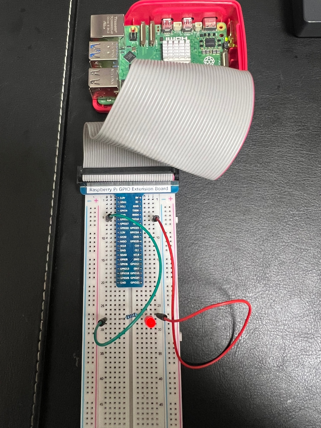
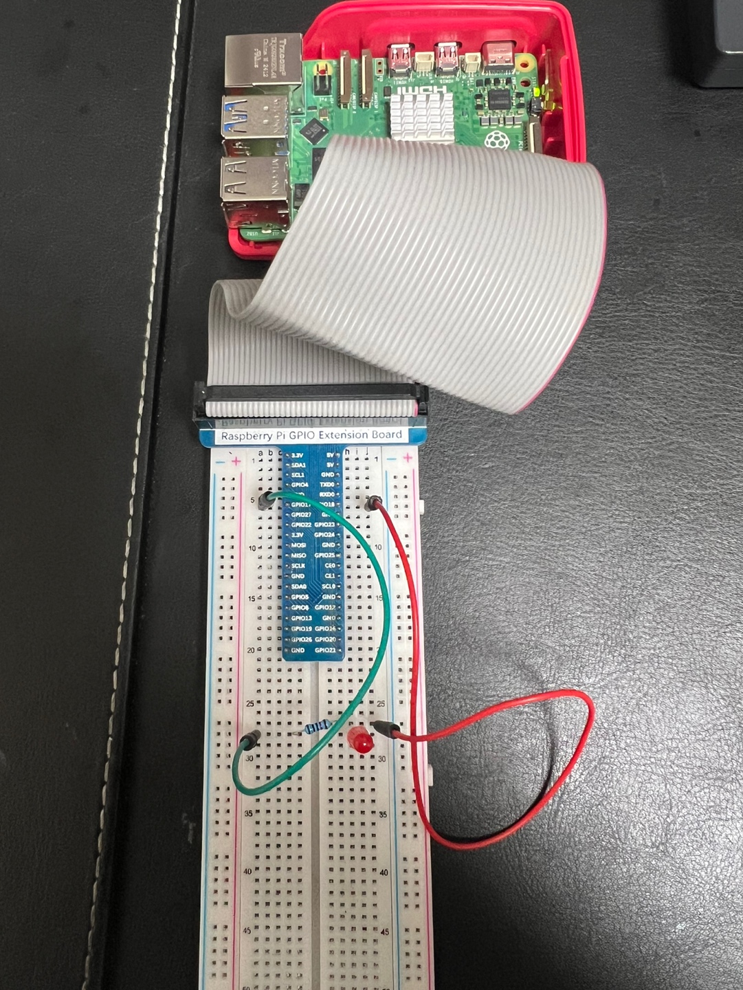
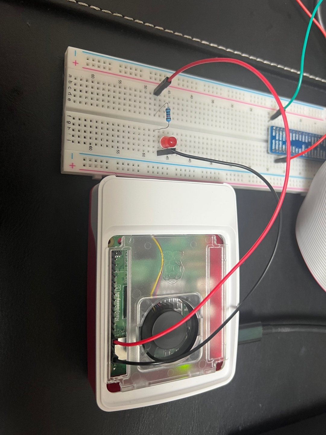
GPIO
nGene LED Character Misc Driver
LED light ON with GPIO Extension Board
LED light OFF with GPIO Extension Board
LED Driver Quick Guide (v0.1.1 · Raspberry Pi 5 · Linux 6.12.34+rpt-rpi-2712)
Purpose. Character device that toggles an LED using one or two GPIO lines.
Uses legacy integer GPIO API (gpio_request/gpio_direction_*).
Registers as a miscdevice so /dev/nGene_led is created automatically.
gpiodetect
gpioinfo gpiochip0 | grep -E "line +17:|line +18:"
gpioset -m time -s 1 gpiochip0 17=1 18=0    # LED ON  for 1s
gpioset -m time -s 1 gpiochip0 17=0 18=1    # LED OFF for 1s
Important: compute correct Linux “global” GPIO numbers
sudo mount -t debugfs none /sys/kernel/debug 2>/dev/null || true
awk '
  /^gpiochip/ { chip=$1; base=$2; ngpio=$4 }
  /label:/    { lbl=$2; printf("chip=%s base=%s ngpio=%s label=%s\n", chip, base, ngpio, lbl) }
' /sys/kernel/debug/gpio | sed -n '1,120p'

# On your Pi 5 this showed: chip=gpiochip0 base=571 label=pinctrl-rp1
# Therefore:
#   BCM17 → 571+17 = 588
#   BCM18 → 571+18 = 589
Build
make clean && make
Load (examples)
Two-pin sink mode (BCM17/18; out=588, in=589; ON ⇒ out=1, in=0)
Use a series resistor (330–1000 Ω). GPIOs are 3.3 V only.
Show v0.1.0 Quick Guide (older)
LED Driver Quick Guide (v0.1.0 · Raspberry Pi 5 · Linux 6.12.34+rpt-rpi-2712)
Purpose. Minimal character device that toggles an LED using one or two GPIO lines.
Uses legacy integer GPIO API (gpio_request/gpio_direction_*). No gpiod internals.
gpiodetect
gpioinfo gpiochip0 | grep -E "line +17:|line +18:"
gpioset -m time -s 1 gpiochip0 17=1 18=0 # LED ON for 1s
gpioset -m time -s 1 gpiochip0 17=0 18=1 # LED OFF for 1s
Build
make clean && make
Important: compute correct Linux “global” GPIO numbers
sudo mount -t debugfs none /sys/kernel/debug 2>/dev/null || true
awk '
/^gpiochip/ { chip=$1; base=$2; ngpio=$4 }
/label:/ { lbl=$2; printf("chip=%s base=%s ngpio=%s label=%s\n", chip, base, ngpio, lbl) }
' /sys/kernel/debug/gpio | sed -n '1,120p'
# On your Pi 5 this showed: chip=gpiochip0 base=571 label=pinctrl-rp1
# Therefore:
# BCM17 → 571+17 = 588
# BCM18 → 571+18 = 589
Load (examples)
One-pin mode (BCM17 only; anode on BCM17 via 330–1000 Ω, cathode to GND)
echo 1 | sudo tee /dev/nGene_led >/dev/null # LED ON
echo 0 | sudo tee /dev/nGene_led >/dev/null # LED OFF
Check logs / Unload
sudo dmesg -w
sudo rmmod nGene_RaspPi5_LED
Written on August 13, 2025
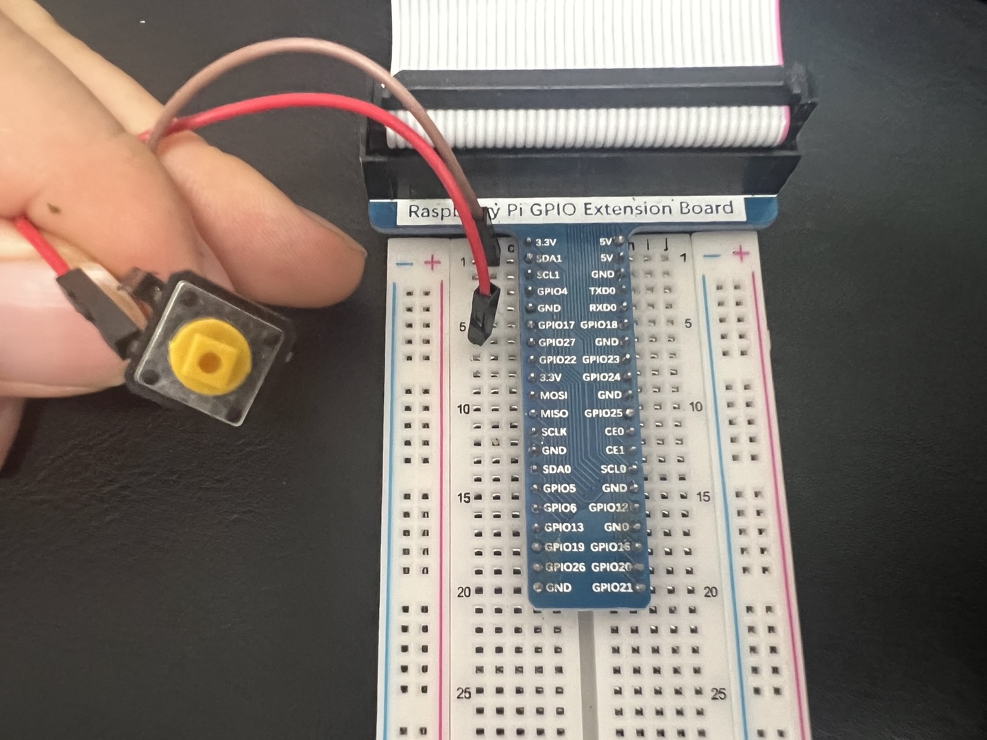
nGene Switch Interrupt Driver
nGene Switch Interrupt Driver Quick Guide (v0.1.0-dev · Raspberry Pi 5, Linux 6.12.34+rpt-rpi-2712)
Purpose.
Platform driver that binds to a Device Tree overlay node
(compatible = "ngene,switch-int") and reads an
active-high push button via the
switch-gpios property. The driver exposes:
/dev/nGene_interrupt_device and
/proc/nGene_proc_char_device.
Troubleshooting: “Unknown error 517” (EPROBE_DEFER) on insmod
# 1) Ensure the overlay is loaded:
sudo dtoverlay -l
# 2) If not present, (re)load it:
sudo dtoverlay -v ./ngene-switch-int.dtbo pin=17
# 3) Make sure no userspace program is holding the line:
sudo killall -q gpiomon gpioset gpioget pigpiod 2>/dev/null || true
Unload (driver and overlay)
sudo rmmod nGene_Switch_Interrupt_driver
sudo dtoverlay -l # note the index (e.g., 0)
sudo dtoverlay -r 0
Written on August 19, 2025
Device tree overlays for the nGene switch interrupt driver (v0.1.0-dev) (Written August 19, 2025)
I. Purpose and scope
This document refines the explanation of why a Device Tree (DT) overlay is required for the
nGene Switch Interrupt driver, how to compile and apply the overlay, and—most critically—
how to interpret dtoverlay diagnostics and hexdumps to validate a correct result.
The target environment is Raspberry Pi 5 (BCM2712) with a recent Linux kernel where GPIO and IRQ
ownership are described via the Device Tree.
II. Why a DT overlay is required
A DT overlay provides the kernel with a precise, declarative description of the intended wiring and
binding. It creates a platform device whose compatible string matches the driver, and it supplies
a switch-gpios property that identifies the GPIO line and polarity used for edge interrupts.
This unified description ensures that pin control, IRQ routing, and driver binding share the same
source of truth, avoiding conflicts with other overlays and alternate pin functions.
Device instantiation. The overlay introduces a node whose compatible matches the driver’s of_match_table, enabling ngene_probe() to run when the module loads.
GPIO assignment. The switch-gpios triplet (controller phandle, pin index, flags) allows devm_gpiod_get(...,"switch", GPIOD_IN) to acquire the exact line.
Runtime variability. A __overrides__ stanza permits changing the pin index at overlay load time via a simple parameter, without editing the DTS.
Hygiene and safety. Centralizing ownership in DT prevents userspace tools from racing the kernel for the same pin and clarifies intent across the system.
III. Reference overlay source (DTS)
/dts-v1/;
/plugin/;
/*
nGene Switch Interrupt overlay (v0.1.0-dev)
Creates a platform device:
compatible = "ngene,switch-int";
switch-gpios = <&gpio 17 0>; (default BCM pin = 17, flags=0 means ACTIVE_HIGH)
Change the pin at load time:
sudo dtoverlay ./ngene-switch-int.dtbo pin=<N>
*/
/ {
compatible = "brcm,bcm2712";
fragment@0 {
target-path = "/";
__overlay__ {
/* Node name without unit-address to avoid unit_address_vs_reg warning */
ngene_switch_int: ngene-switch-int {
compatible = "ngene,switch-int";
/* flags=0 == GPIO_ACTIVE_HIGH; use 1 for ACTIVE_LOW if needed */
switch-gpios = <&gpio 17 0>;
status = "okay";
};
};
};
/* Override the 2nd cell (the pin index) of the 3-cell 'switch-gpios'
Cells: [ phandle | pin | flags ] -> offset 4 bytes selects 'pin' */
__overrides__ {
pin = <&ngene_switch_int>, "switch-gpios:4";
};
};
IV. Anatomy and expectations
Element
What it conveys
What to expect at runtime
compatible = "ngene,switch-int"
Binding identity for the platform device.
Driver probe runs when module is inserted.
switch-gpios = <&gpio 17 0>
Three cells: GPIO controller phandle, BCM pin index, flags.
Hexdump shows 12 bytes; middle cell equals 0x00000011 for BCM 17; flags 0 for active-high.
__overrides__{ pin = ..., "switch-gpios:4" }
Permits pin=<N> on load; edits the pin cell in-place.
Load overlay first; verify with dtoverlay -l; attempt insmod again.
XI. Summary
Correct application of the ngene-switch-int overlay is demonstrated by three converging signals:
verbose dtoverlay diagnostics that show the pin cell override at offset 4; a resident overlay
listing with the chosen parameter; and a 12-byte switch-gpios property whose middle cell equals
the selected BCM pin. These checks establish that the kernel’s Device Tree, IRQ routing, and the
driver’s binding context are aligned, enabling reliable delivery of rising-edge interrupts from the
designated GPIO line.
Written on August 19, 2025
PWM
nGene LED PWM Character Misc Driver
LED PWM Character Misc Driver Quick Guide (v0.1.0 · Raspberry Pi 5, Linux 6.12.34+rpt-rpi-2712)
Purpose.
Character device driver that controls an LED via a single GPIO output or
optional two-pin sink mode.
Provides both ON/OFF control and software-based PWM
(implemented with hrtimer and a private ordered workqueue).
Operates on any valid GPIO without requiring device-tree overlays.
Registers as a miscdevice, creating
/dev/nGene_led by default.
gpiodetect
gpioinfo gpiochip0 | grep -E "line +17:|line +18:"
gpioset -m time -s 1 gpiochip0 18=1 # Set high for 1s
gpioset -m time -s 1 gpiochip0 18=0 # Set low for 1s
Important: Compute correct Linux “global” GPIO numbers
Note: Disable any hardware PWM overlay on the chosen pins in /boot/firmware/config.txt or GPIO control will be preempted.
Verify device node
ls -l /dev/nGene_led
# EXPECT: leading 'c' (character device), major 10 (misc), e.g.:
# crw-rw-rw- 1 root root 10, 123 ... /dev/nGene_led
Basic toggle (steady ON/OFF)
echo 1 | sudo tee /dev/nGene_led > /dev/null   # LED ON
sleep 1
echo 0 | sudo tee /dev/nGene_led > /dev/null   # LED OFF
Software PWM control
Default: 1 kHz frequency, 50 % duty cycle.
echo "d=50"  | sudo tee /dev/nGene_led > /dev/null   # Set duty to 50 % (starts PWM)
echo "f=500" | sudo tee /dev/nGene_led > /dev/null   # Set frequency to 500 Hz
echo "stop"  | sudo tee /dev/nGene_led > /dev/null   # Stop PWM (maintains output level)
echo "start" | sudo tee /dev/nGene_led > /dev/null   # Resume PWM
Gradual brightness change demonstration
Brightness can be adjusted in steps by varying the PWM duty cycle:
echo "d=0"  | sudo tee /dev/nGene_led > /dev/null   # LED fully off
echo "d=10" | sudo tee /dev/nGene_led > /dev/null   # LED dim
echo "d=90" | sudo tee /dev/nGene_led > /dev/null   # LED bright
Duty cycle: 0% (LED fully off)
Duty cycle: 10% (LED dim)
Duty cycle: 90% (LED bright)
Diagnostics and recovery
echo "reset"   | sudo tee /dev/nGene_led > /dev/null  # Stop PWM + force steady LOW
echo "probe"   | sudo tee /dev/nGene_led > /dev/null  # Report live GPIO output level
echo "invert"  | sudo tee /dev/nGene_led > /dev/null  # Toggle software polarity
echo "reclaim" | sudo tee /dev/nGene_led > /dev/null  # Re-request GPIO and re-apply output mode
Important: If you need I²C on GPIO2 (pin 3) / GPIO3 (pin 5), keep dtparam=i2c_arm=on in /boot/firmware/config.txt; if you want those pins as normal GPIO instead, comment it out.
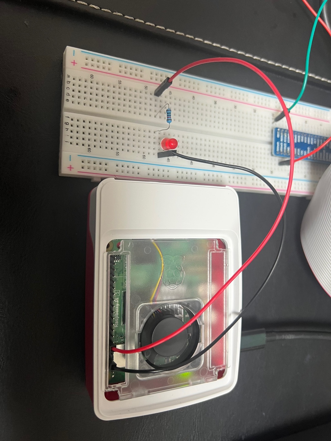
nGene I²C BMP280 Character Misc Driver (Temperature sensor)
I²C BMP280 Character Misc Driver Quick Guide (v0.1.1 · Raspberry Pi 5 · Linux 6.12.34+rpt-rpi-2712)
Purpose.
Character driver for Bosch BMP280 (temperature & pressure). Registers as a
miscdevice (/dev/nGene_bmp by default).
Adds poll() support so a single open can block until new data is ready, enabling
streaming reads (e.g., cat /dev/nGene_bmp | head -n 5 produces 5 timed lines).
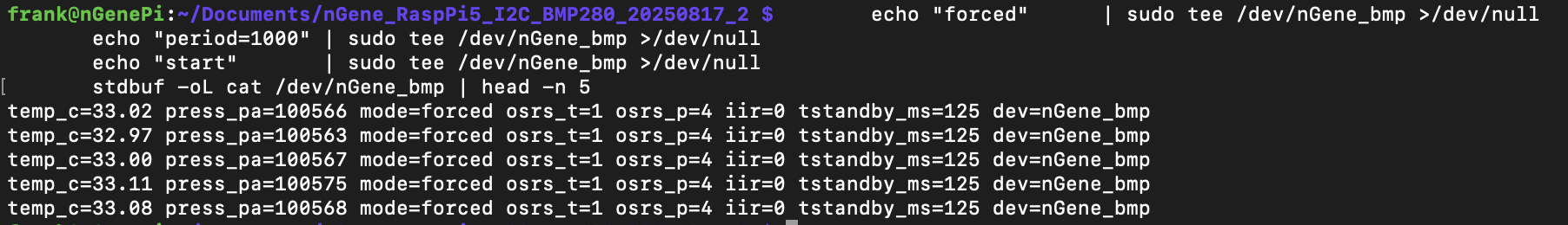
# Put driver in 1 Hz forced sampler mode
echo "forced"      | sudo tee /dev/nGene_bmp >/dev/null
echo "period=1000" | sudo tee /dev/nGene_bmp >/dev/null
echo "start"       | sudo tee /dev/nGene_bmp >/dev/null

# One open: multiple lines delivered at 1 s interval
stdbuf -oL cat /dev/nGene_bmp | head -n 5
Earlier version v0.1.0 (baseline, no poll)
I²C BMP280 Character Misc Driver Quick Guide (v0.1.0 · Raspberry Pi 5, Linux 6.12.34+rpt-rpi-2712)
Purpose.
Character device driver for Bosch BMP280 (temperature & pressure) on Raspberry Pi 5.
Registers as a miscdevice (default /dev/nGene_bmp) and exposes a simple text interface:
cat /dev/nGene_bmp for a one-line status, and echo "<cmd>" > /dev/nGene_bmp for configuration/diagnostics.
This reuses the nGene misc/locking backbone from the LED/PWM driver, but removes PWM/GPIO and adds I²C/SMBus transactions for BMP280.
nGene I²C MPU-6050 Character Misc Driver (Gyroscope sensor)
I²C MPU-6050 Character Misc Driver Quick Guide (v0.1.0-dev)
Purpose.
Character driver for InvenSense MPU-6050 (3-axis accel + 3-axis gyro + temp). Registers as a
miscdevice (/dev/nGene_mpu by default). Supports poll() and a built-in sampler so a single open can stream timed lines (e.g.,
cat /dev/nGene_mpu | head -n 5 prints 5 lines at the configured cadence).
sudo emacs -nw /boot/firmware/config.txt
# add / ensure:
dtparam=i2c_arm=on
# also load the userspace helper:
echo i2c-dev | sudo tee /etc/modules-load.d/i2c.conf
sudo modprobe i2c-dev
sudo reboot
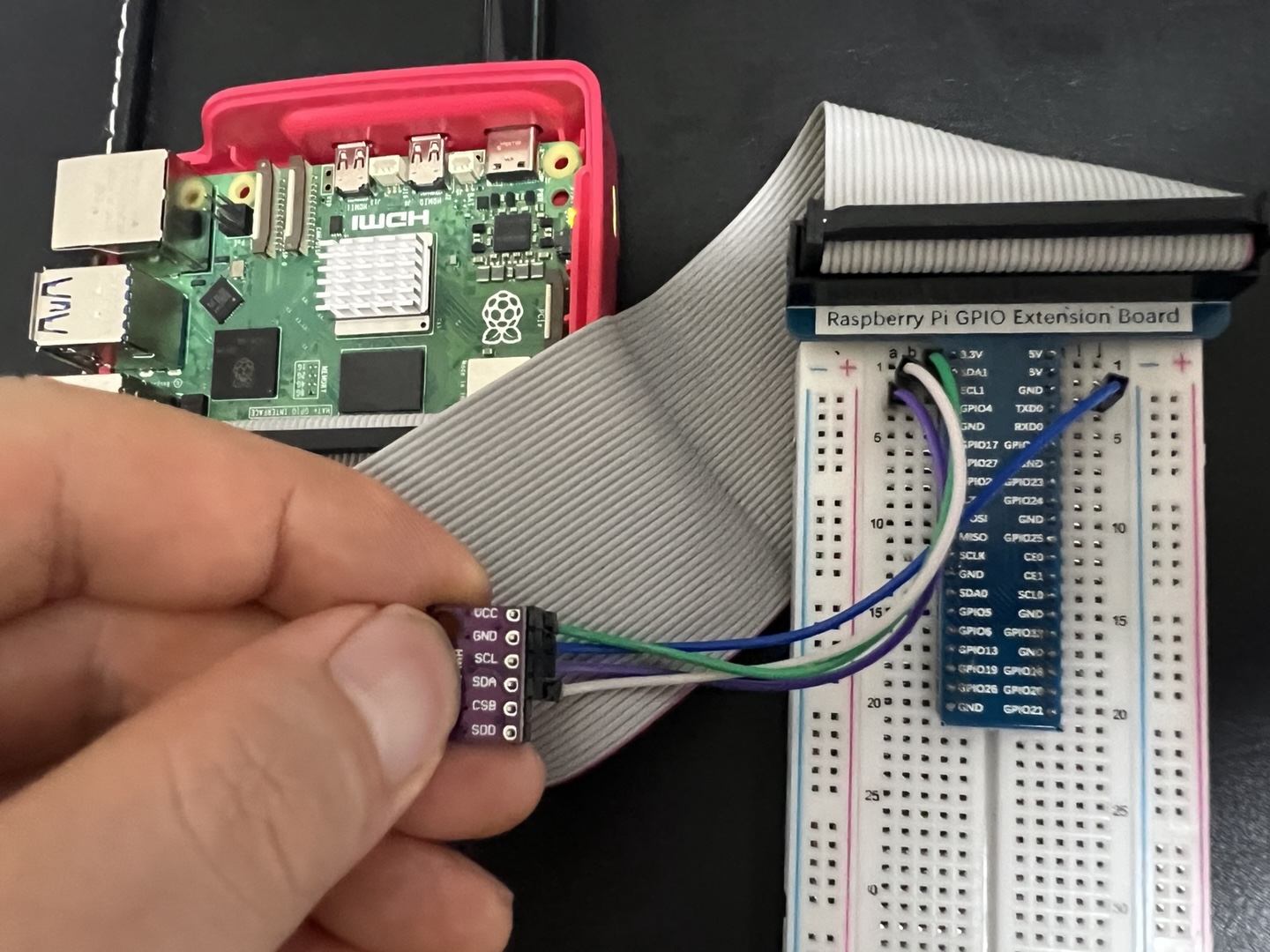
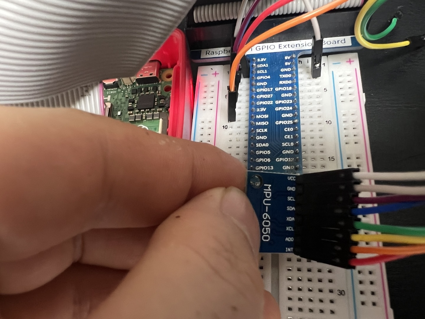
2) Wiring (3.3V only, 40-pin header)
VCC  -> 3V3 (pin 1 or 17)
GND  -> any GND (pin 6/9/14/20/25/30/34/39)
SDA  -> pin 3 (GPIO2 / I2C1 SDA)
SCL  -> pin 5 (GPIO3 / I2C1 SCL)
AD0  -> GND => address 0x68    |    AD0 -> 3V3 => address 0x69
INT  -> (optional) a 3.3V GPIO input (e.g., GPIO17 / pin 11) if you add IRQ handling later
XDA/XCL -> leave unconnected (aux I²C pass-through)
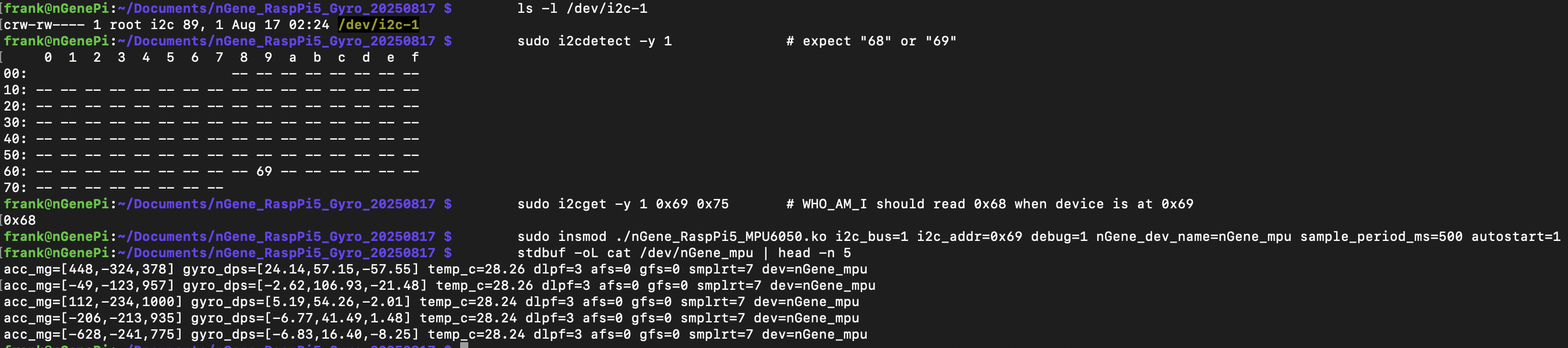
3) Probe bus
ls -l /dev/i2c-1
sudo i2cdetect -y 1                # expect "68" or "69"
# If AD0=3V3 (addr=0x69), WHO_AM_I still reads 0x68 from register 0x75:
sudo i2cget -y 1 0x69 0x75         # expect 0x68
4) Build
make clean && make
5) Load
# Remove first to avoid "File exists"
sudo rmmod nGene_RaspPi5_MPU6050 2>/dev/null || true

# If your board straps AD0=3V3 (address 0x69), autostart the sampler at 0.5 s:
sudo insmod ./nGene_RaspPi5_MPU6050.ko i2c_bus=1 i2c_addr=0x69 debug=1 nGene_dev_name=nGene_mpu sample_period_ms=500 autostart=1

dmesg | tail -n 80

# With autostart=1, this will block and print a line every 0.5 s
stdbuf -oL cat /dev/nGene_mpu | head -n 5
6) Commands (echo to the device; case-insensitive)
# Basic diag / power
echo "probe"    | sudo tee /dev/nGene_mpu >/dev/null   # WHO_AM_I (expect 0x68)
echo "reset"    | sudo tee /dev/nGene_mpu >/dev/null   # device reset + reconfig
echo "sleep"    | sudo tee /dev/nGene_mpu >/dev/null   # set sleep bit
echo "wake"     | sudo tee /dev/nGene_mpu >/dev/null   # clear sleep, PLL clock

# Filters and ranges
echo "dlpf=3"   | sudo tee /dev/nGene_mpu >/dev/null   # 0..6 (default 3)
echo "afs=0"    | sudo tee /dev/nGene_mpu >/dev/null   # accel ±2g/±4g/±8g/±16g -> 0..3
echo "gfs=0"    | sudo tee /dev/nGene_mpu >/dev/null   # gyro  ±250/±500/±1000/±2000 dps -> 0..3
echo "smplrt=7" | sudo tee /dev/nGene_mpu >/dev/null   # SMPLRT_DIV (1kHz/(1+div) with DLPF on)

# Address / rebinding
echo "addr=0x69" | sudo tee /dev/nGene_mpu >/dev/null  # set then:
echo "reclaim"   | sudo tee /dev/nGene_mpu >/dev/null  # drop/reacquire client + reapply config

# Sampler (poll-friendly streaming)
echo "period=500" | sudo tee /dev/nGene_mpu >/dev/null # 500 ms
echo "start"      | sudo tee /dev/nGene_mpu >/dev/null
echo "stop"       | sudo tee /dev/nGene_mpu >/dev/null
Streaming demo
echo "period=500" | sudo tee /dev/nGene_mpu >/dev/null
echo "start"      | sudo tee /dev/nGene_mpu >/dev/null
stdbuf -oL cat /dev/nGene_mpu | head -n 5
Troubleshooting
# If insmod fails with "No such device" or "I/O error"
ls -l /dev/i2c-1
sudo i2cdetect -y 1                # make sure 0x68 or 0x69 is present

# If the address is already owned by an in-tree driver:
sudo modprobe -r mpu6050 inv_mpu6050_i2c 2>/dev/null || true
sudo rmmod nGene_RaspPi5_MPU6050 2>/dev/null || true
sudo insmod ./nGene_RaspPi5_MPU6050.ko i2c_bus=1 i2c_addr=0x69 debug=1

# Live logs
dmesg | tail -n 80
journalctl -k -f
Revert (disable I²C) — optional
sudo emacs -nw /boot/firmware/config.txt
# comment the line back:
# dtparam=i2c_arm=on
sudo rm -f /etc/modules-load.d/i2c.conf
sudo reboot
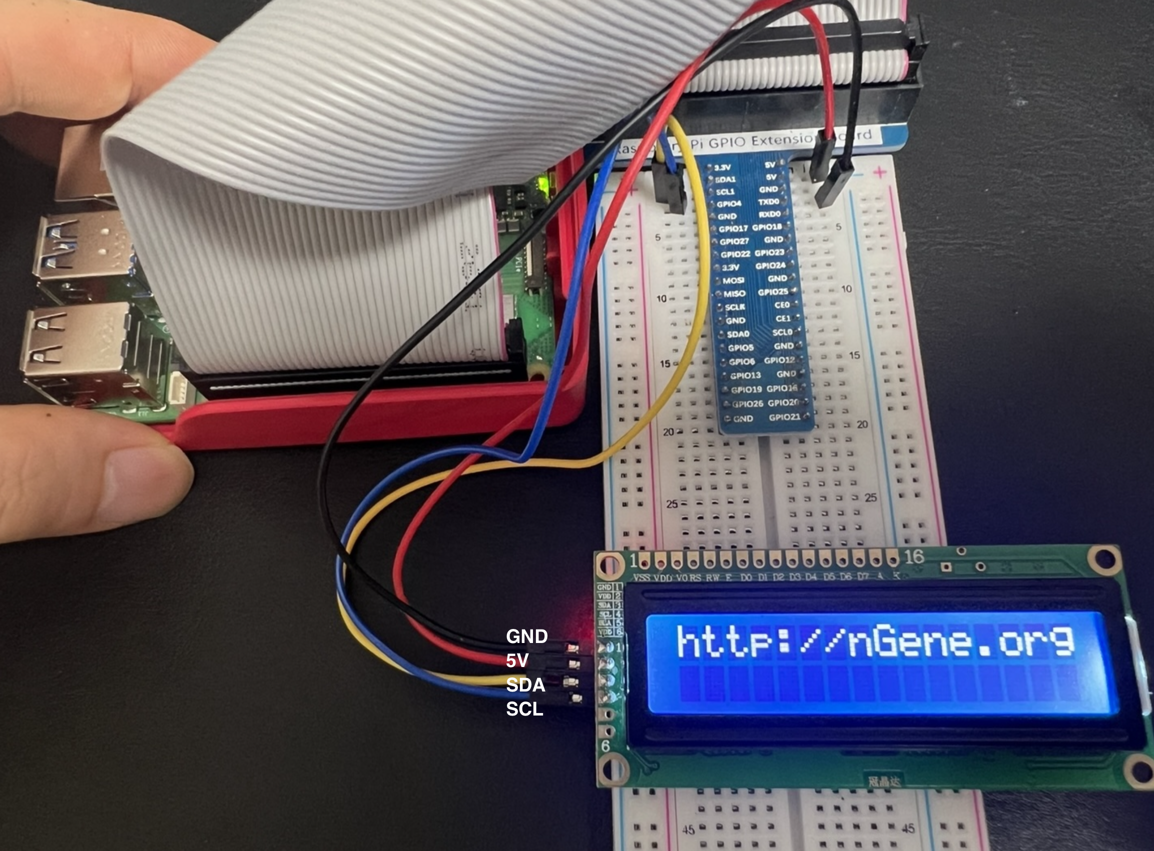
nGene I²C LCD Character Misc Driver
I²C 1602 LCD Character Misc Driver Quick Guide (v0.1.0-dev)
Purpose.
Character driver for HD44780-class 1602 LCD modules with PCF8574 I²C backpacks
(labels such as “1602A IIC”, “GJD1602A-IIC”). Registers as a miscdevice
(/dev/nGene_lcd). On module load, initializes the LCD and prints the banner
http://nGene.org. Userspace can update the display by writing one or two lines
(newline separates lines).
Important: Contrast. With backlight on but no characters visible, adjust the small blue trimpot on the backpack; characters typically become visible near one end.
Safety (pull-ups and voltage). The Pi’s I²C lines must be pulled up to 3.3 V.
Many backpacks include pull-ups tied to VCC. If VCC=5 V and those pull-ups are to 5 V,
SDA/SCL are back-driven at 5 V (unsafe). Remove/disable the 5 V pull-ups or ensure pull-ups are at 3.3 V. Powering the backpack at 3.3 V is an alternative on some modules.
3) Probe bus
ls -l /dev/i2c-1
sudo i2cdetect -y 1              # expect 0x27 or 0x3F
# 'UU' before insmod indicates another kernel client already owns the address.
Why (B) & (C) succeed when (A) does not. Many GJD1602A-IIC units use the alternate PCF8574 wiring (map_preset=1), so the default mapping (#0) routes control/data to incorrect pins (no text). Certain modules also require longer EN pulse and/or initial delay; (C) provides additional margin.
6) Update text
echo "Hello, world" | sudo tee /dev/nGene_lcd
printf "Line1 text\nLine2 text" | sudo tee /dev/nGene_lcd
# '\n' moves to line 2; each line is padded/truncated to 16 characters
7) Useful module parameters
# Mapping presets:
map_preset=1                     # alternate, very common (recommended)
map_preset=0                     # default mapping

# Timing margins:
en_high_us=5 en_low_us=60 power_on_ms=80

# Backlight and boot banner:
backlight=1                      # 1=on, 0=off
init_banner="http://nGene.org"   # banner on line 1 at init
Troubleshooting
# Address ownership conflict ('UU' before insmod):
sudo nano /boot/firmware/config.txt   # remove conflicting overlays if present
sudo modprobe -r conflicting_module   # if a bound in-tree client exists
sudo rmmod nGene_RaspPi5_LCD1602_I2C 2>/dev/null || true
sudo insmod ./nGene_RaspPi5_LCD1602_I2C.ko i2c_bus=1 i2c_addr=0x27 map_preset=1

# Live logs:
dmesg | tail -n 80
journalctl -k -f
nGene Sense HAT Driver Quick Guide (v0.1.7-dev · Raspberry Pi 5, Linux 6.12.34+rpt-rpi-2712)
Purpose.
Minimal kernel module that, on insmod, locates the Sense HAT framebuffer
("RPi-Sense FB"), scrolls a tiny 5×7 message across the 8×8 RGB565 LED
matrix once (with rotation/low-light options), then clears. It exposes a runtime
device /dev/nGene_sensehat for text and sensors (env + IMU).
What’s new in v0.1.7-dev
Motion meter:!motion animates the matrix ~1 s; brightness ∝ |accel|-1g.
Level UX: shows a single averaged tilt like “6°” (no “LEVEL ” prefix).
Public IMU symbols: unified nGene_* prefix.
Degree symbol: rendered inline by the scroller (font-independent).
echo -n '!temp'     | sudo tee /dev/nGene_sensehat >/dev/null   # temperature (°C)
echo -n '!hum'      | sudo tee /dev/nGene_sensehat >/dev/null   # humidity (%RH)
echo -n '!pres'     | sudo tee /dev/nGene_sensehat >/dev/null   # pressure (hPa)
echo -n '!compass'  | sudo tee /dev/nGene_sensehat >/dev/null   # heading like "315° NW"
echo -n '!level'    | sudo tee /dev/nGene_sensehat >/dev/null   # tilt: 3× @0.7s → avg once (e.g., "6°")
echo -n '!motion'   | sudo tee /dev/nGene_sensehat >/dev/null   # motion meter: animate ~1s (50 ms step)
echo -n '!cal'      | sudo tee /dev/nGene_sensehat >/dev/null   # IMU calibration (mag hard-iron + scales)
echo -n 'Hello'     | sudo tee /dev/nGene_sensehat >/dev/null   # scroll text once
# Back-compat: "temp", "humidity", "pres" (without '!') still work
Tip: If orientation is off, try rotation=90, 180, or 270.
If colours look odd on your stack, try swap_bytes=1.
Use the device
echo -n '!temp'    | sudo tee /dev/nGene_sensehat >/dev/null
echo -n '!hum'     | sudo tee /dev/nGene_sensehat >/dev/null
echo -n '!pres'    | sudo tee /dev/nGene_sensehat >/dev/null
echo -n '!compass' | sudo tee /dev/nGene_sensehat >/dev/null   # arrow + "DDD° XX"
echo -n '!level'   | sudo tee /dev/nGene_sensehat >/dev/null   # 3 samples @0.7s; shows avg once ("D°")
echo -n '!motion'  | sudo tee /dev/nGene_sensehat >/dev/null   # ~1s animation at 50 ms step
echo -n '!cal'     | sudo tee /dev/nGene_sensehat >/dev/null   # rotate during mag, then keep still
/dev/nGene_sensehat is mode 0666. Reads return the last message:
sudo cat /dev/nGene_sensehat
Optional IIO hints and overrides
# Prefer specific IIO devices by substring:
sudo insmod ./nGene_SenseHAT_bootscroll.ko \
  iio_hint_temp=cpu  iio_hint_hum=hts  iio_hint_pres=lps \
  iio_hint_mag=lsm9  iio_hint_accel=lsm9 msg="nGene"

# Force exact sysfs env attributes (decimal or milli-units ok):
sudo insmod ./nGene_SenseHAT_bootscroll.ko \
  path_hum=/sys/bus/iio/devices/iio:deviceX/in_humidityrelative_input \
  path_pres=/sys/bus/iio/devices/iio:deviceY/in_pressure_input
IMU: raw I²C fallback and addresses
# If IIO isn't present, driver uses safe adapter reads or a temp dummy client.
# You can force bus/addresses if needed:
sudo insmod ./nGene_SenseHAT_bootscroll.ko \
  imu_i2c_bus=1 lsm9_mag_addr=0x1c lsm9_acc_addr=0x6a msg="nGene"
Calibration
# ROTATE (mag range), PAUSE, HOLD (gyro placeholder).
# Stores to /var/lib/ngene_sensehat/imu_cal.bin
echo -n '!cal' | sudo tee /dev/nGene_sensehat >/dev/null
Unload (clears again on exit)
sudo rmmod nGene_SenseHAT_bootscroll
Expected dmesg on success
nGene_SenseHAT v0.1.7-dev loading
nGene_SenseHAT: using /dev/fb0 (Sense HAT)
nGene_SenseHAT: scrolling "nGene" (...)
nGene_SenseHAT: created /dev/nGene_sensehat
nGene_SenseHAT: init done.

# Compass example
nGene_SenseHAT(IMU): LSM9DS1 mag configured via adapter (addr=0x1c, bus=1)
nGene_SenseHAT(IMU): heading 270 deg W (cal:ON) raw[mx=-2198,my=520,mz=-1249]

# Level example
nGene_SenseHAT(IMU): LEVEL — sampling tilt @0.7s for 3 samples...
nGene_SenseHAT(IMU): LEVEL sample 1/3: ax=-92 ay=16 az=863 mg -> tilt=6 deg
...
# Motion example
nGene_SenseHAT(IMU): MOTION — sampling @50ms for 1000ms...
We write full 8×8 RGB565 frames to screen_base and then queue the first framebuffer
page into fbdefio->pagereflist, scheduling the deferred work so the LED matrix updates.
IMU uses IIO first; if absent, it falls back to safe I²C adapter reads or a temporary dummy client.
The degree symbol (0xB0) is rendered inline by the scroller, so it always displays correctly.
Level samples 3× at 700 ms intervals and displays a single averaged tilt angle in degrees.
Motion runs for ~1 s with a ~50 ms step, mapping |accel|-1g to LED brightness.
Show v0.1.6 Quick Guide (older)
nGene Sense HAT Driver Quick Guide (v0.1.6-dev · Raspberry Pi 5, Linux 6.12.34+rpt-rpi-2712)
Purpose.
Minimal kernel module that, on insmod, locates the Sense HAT framebuffer
("RPi-Sense FB"), scrolls a tiny 5×7 message across the 8×8 RGB565 LED
matrix once (with rotation/low-light options), then clears. It exposes a runtime
device /dev/nGene_sensehat for text and sensors (env + IMU):
echo -n '!temp'     | sudo tee /dev/nGene_sensehat >/dev/null   # temperature (°C)
echo -n '!hum'      | sudo tee /dev/nGene_sensehat >/dev/null   # humidity (%RH)
echo -n '!pres'     | sudo tee /dev/nGene_sensehat >/dev/null   # pressure (hPa)
echo -n '!compass'  | sudo tee /dev/nGene_sensehat >/dev/null   # heading like "315° NW"
echo -n '!level'    | sudo tee /dev/nGene_sensehat >/dev/null   # tilt: samples 3× @0.7s; shows avg once (e.g., "6°")
echo -n '!cal'      | sudo tee /dev/nGene_sensehat >/dev/null   # IMU calibration (mag hard-iron + scales)
echo -n 'Hello'     | sudo tee /dev/nGene_sensehat >/dev/null   # scroll text once
# Back-compat: "temp", "humidity", "pres" (without '!') still work
Tip: If orientation is off, try rotation=90, 180, or 270.
If colours look odd on your stack, try swap_bytes=1 (degree/white/black unaffected).
Use the device
echo -n '!temp'    | sudo tee /dev/nGene_sensehat >/dev/null
echo -n '!hum'     | sudo tee /dev/nGene_sensehat >/dev/null
echo -n '!pres'    | sudo tee /dev/nGene_sensehat >/dev/null
echo -n '!compass' | sudo tee /dev/nGene_sensehat >/dev/null   # shows arrow + "DDD° XX"
echo -n '!level'   | sudo tee /dev/nGene_sensehat >/dev/null   # 3 samples @0.7s; shows avg once (e.g., "6°")
echo -n '!cal'     | sudo tee /dev/nGene_sensehat >/dev/null   # rotate during mag, then keep still
/dev/nGene_sensehat is mode 0666. Reads return last message:
sudo cat /dev/nGene_sensehat
Optional IIO hints and overrides
# Prefer specific IIO devices by substring:
sudo insmod ./nGene_SenseHAT_bootscroll.ko \
  iio_hint_temp=cpu  iio_hint_hum=hts  iio_hint_pres=lps \
  iio_hint_mag=lsm9  iio_hint_accel=lsm9 msg="nGene"

# Force exact sysfs env attributes (decimal or milli-units ok):
sudo insmod ./nGene_SenseHAT_bootscroll.ko \
  path_hum=/sys/bus/iio/devices/iio:deviceX/in_humidityrelative_input \
  path_pres=/sys/bus/iio/devices/iio:deviceY/in_pressure_input
IMU: raw I²C fallback and addresses
# If IIO isn't present, driver uses safe adapter reads or a temp dummy client.
# You can force bus/addresses if needed:
sudo insmod ./nGene_SenseHAT_bootscroll.ko \
  imu_i2c_bus=1 lsm9_mag_addr=0x1c lsm9_acc_addr=0x6a msg="nGene"
Compass uses LSM9DS1 magnetometer. Level uses accelerometer; samples 3× at 700 ms,
shows only the averaged degrees once. Degree symbol is rendered inline (no font dependency).
Calibration
# Starts 3 phases: ROTATE (mag range), PAUSE, HOLD (gyro placeholder).
# Stores to /var/lib/ngene_sensehat/imu_cal.bin
echo -n '!cal' | sudo tee /dev/nGene_sensehat >/dev/null
Unload (clears again on exit)
sudo rmmod nGene_SenseHAT_bootscroll
Expected dmesg on success
nGene_SenseHAT v0.1.6-dev loading
nGene_SenseHAT: using /dev/fb0 (Sense HAT)
nGene_SenseHAT: scrolling "nGene" (5 chars, ... cols, 100 ms/col, rot=0, low_light=1)
nGene_SenseHAT: created /dev/nGene_sensehat
nGene_SenseHAT: init done.

# Compass example (with calibration loaded/saved)
nGene_SenseHAT(IMU): LSM9DS1 mag configured via adapter (addr=0x1c, bus=1)
nGene_SenseHAT(IMU): heading 270 deg W (cal:ON) raw[mx=-2198,my=520,mz=-1249]

# Level example (IIO accel not found → raw I²C fallback)
nGene_SenseHAT(IMU): LEVEL — sampling tilt @0.7s interval for 3 samples...
nGene_SenseHAT(IMU): LSM9DS1 accel enabled via adapter (addr=0x6a, bus=1)
nGene_SenseHAT(IMU): LEVEL sample 1/3: ax=-92 ay=16 az=863 mg -> tilt=6 deg
nGene_SenseHAT(IMU): LEVEL sample 2/3: ax=-103 ay=18 az=958 mg -> tilt=6 deg
nGene_SenseHAT(IMU): LEVEL sample 3/3: ax=-102 ay=18 az=958 mg -> tilt=6 deg
We write full 8×8 RGB565 frames to screen_base and then queue the first framebuffer
page into fbdefio->pagereflist, scheduling the deferred work so the LED matrix
reliably updates. IMU uses IIO first; if absent, it falls back to safe I²C adapter reads or a
temporary dummy client. The degree symbol (0xB0) is rendered inline by the scroller,
so it always displays correctly even if the base font lacks it. The level command samples
3× at 700 ms intervals and displays a single averaged tilt angle in degrees.
Show v0.1.3 Quick Guide (older)
nGene Sense HAT Driver Quick Guide (v0.1.3-dev · Raspberry Pi 5, Linux 6.12.34+rpt-rpi-2712)
Purpose.
Minimal kernel module that, on insmod, locates the Sense HAT framebuffer
("RPi-Sense FB"), scrolls a tiny 5×7 message across the 8×8 RGB565 LED
matrix once (with rotation/low-light options), then clears. It also exposes a runtime
device /dev/nGene_sensehat for text and sensor display:
echo -n '!temp' | sudo tee /dev/nGene_sensehat >/dev/null   # show temperature (°C)
echo -n '!hum'  | sudo tee /dev/nGene_sensehat >/dev/null   # show humidity (%RH)
echo -n '!pres' | sudo tee /dev/nGene_sensehat >/dev/null   # show pressure (hPa)
echo -n 'Hello' | sudo tee /dev/nGene_sensehat >/dev/null   # scroll text once
# Back-compat: "temp", "humidity", "pres" (without '!') still work
dmesg | grep -i "RPi-Sense FB"
for f in /sys/class/graphics/fb[0-7]/name; do echo -n "$f: "; cat "$f"; done
# Expect one line like:
# /sys/class/graphics/fb0/name: RPi-Sense FB
Tip: If orientation is off, try rotation=90, 180, or 270.
If colours ever look odd on your stack, try swap_bytes=1 (white/black unaffected).
Trigger from userspace (bang-prefixed commands)
echo -n '!temp' | sudo tee /dev/nGene_sensehat >/dev/null
echo -n '!hum'  | sudo tee /dev/nGene_sensehat >/dev/null
echo -n '!pres' | sudo tee /dev/nGene_sensehat >/dev/null
echo -n 'Hello!'| sudo tee /dev/nGene_sensehat >/dev/null
Device is /dev/nGene_sensehat (mode 0666 by default). Reads return the last message:
sudo cat /dev/nGene_sensehat
Optional IIO hints (validated) and exact sysfs overrides
# Prefer a specific IIO device by substring:
sudo insmod ./nGene_SenseHAT_bootscroll.ko iio_hint_hum=hts iio_hint_pres=lps msg="nGene"

# Force exact sysfs attribute files (decimal or milli-units accepted):
sudo insmod ./nGene_SenseHAT_bootscroll.ko \
  path_hum=/sys/bus/iio/devices/iio:deviceX/in_humidityrelative_input \
  path_pres=/sys/bus/iio/devices/iio:deviceY/in_pressure_input
Raw I²C fallback (automatic)
# You can force bus/addresses if needed:
sudo insmod ./nGene_SenseHAT_bootscroll.ko i2c_bus=1 hts_addr=0x5f lps_addr=0x5c msg="nGene"
If the address is owned by another kernel driver, we read safely via the adapter (no dummy client).
If it’s free, we create a temporary dummy client and read via SMBus helpers.
Unload (clears again on exit)
sudo rmmod nGene_SenseHAT_bootscroll
Expected dmesg on success
nGene_SenseHAT v0.1.3-dev loading
nGene_SenseHAT: using /dev/fb0 (Sense HAT)
nGene_SenseHAT: scrolling "nGene" (5 chars, ... cols, 100 ms/col, rot=0, low_light=1)
nGene_SenseHAT: created /dev/nGene_sensehat
nGene_SenseHAT: init done.

# Sensor reads (examples; path depends on your setup)
nGene_SenseHAT: Temperature (hwmon:temp1_input) 50.1C (dir=/sys/class/hwmon/hwmon0)
nGene_SenseHAT: Humidity (i2c/hts221) 37.00% (bus=1 addr=0x5f)
nGene_SenseHAT: Pressure (iio) 1012.3hPa (dir=/sys/bus/iio/devices/iio:deviceX)
Parameters
rotation — 0|90|180|270. Default 0.
low_light — 1 dims to ~35% via RGB565 scaling. Default 1.
scroll_ms — ms per column; default 100.
msg — string to scroll once at module load; default "Frank".
We write full 8×8 RGB565 frames to screen_base and then queue the first framebuffer
page into fbdefio->pagereflist, scheduling info->deferred_work so the
Sense HAT LED matrix reliably updates. Pressure uses IIO/HWMON when available; otherwise a safe
I²C adapter read is used when the address is owned by a kernel driver, or a temporary dummy client
is created if free.
Show v0.1.1 Quick Guide (older)
Sense HAT Bootscroll Driver Quick Guide (v0.1.1-dev · Raspberry Pi 5, Linux 6.12.34+rpt-rpi-2712)
Purpose.
Minimal kernel module that, on insmod, locates the Sense HAT framebuffer
("RPi-Sense FB"), scrolls a tiny 5×7 “Frank” across
the 8×8 RGB565 LED matrix once (with rotation/low-light options), then clears.
Frames are written directly to screen_base and deferred-IO is explicitly
kicked so LEDs update reliably.
New in v0.1.1-dev: exposes a runtime writer /dev/nGene_sensehat.
Write a line to scroll it once; read returns the last message.
dmesg | grep -i "RPi-Sense FB"
for f in /sys/class/graphics/fb[0-7]/name; do echo -n "$f: "; cat "$f"; done
# Expect one line like:
# /sys/class/graphics/fb0/name: RPi-Sense FB
Tip: If orientation is off, try rotation=90, 180, or 270.
If colours ever look odd on your stack, try swap_bytes=1 (white/black unaffected).
Send text at runtime (no re-insmod needed)
# scroll once:
echo -n "Hello!" | sudo tee /dev/nGene_sensehat >/dev/null
# read back last message:
sudo cat /dev/nGene_sensehat
Device is created as /dev/nGene_sensehat (mode 0666 by default). The module keeps the
Sense HAT framebuffer open while loaded, so runtime writes update reliably.
We write full 8×8 RGB565 frames to screen_base and then queue the first framebuffer
page into fbdefio->pagereflist, scheduling info->deferred_work so the
Sense HAT LED matrix reliably updates (regardless of deferred-IO settings). If colours ever look
wrong on your stack, try swap_bytes=1 (white/black are unaffected).
Show v0.1.0 Quick Guide (older)
Sense HAT Bootscroll Driver Quick Guide (v0.1.0-dev · Raspberry Pi 5, Linux 6.12.34+rpt-rpi-2712)
Purpose.
Minimal kernel module that, on insmod, locates the Sense HAT framebuffer
("RPi-Sense FB"), scrolls a tiny 5×7 “Frank” across
the 8×8 RGB565 LED matrix once (with rotation/low-light options), then clears.
Writes frames directly to screen_base and explicitly kicks deferred-IO
to ensure the LEDs update on all stacks.
dmesg | grep -i "RPi-Sense FB"
for f in /sys/class/graphics/fb[0-7]/name; do echo -n "$f: "; cat "$f"; done
# Expect one line like:
# /sys/class/graphics/fb0/name: RPi-Sense FB
Tip: If orientation is off, try rotation=90, 180, or 270.
White/black aren’t affected by byte order, but if colours ever look odd on your stack, try swap_bytes=1.
We write full 8×8 RGB565 frames to screen_base and then queue the first framebuffer
page into fbdefio->pagereflist, scheduling info->deferred_work so the
Sense HAT LED matrix reliably updates (regardless of deferred-IO settings). If colours ever look
wrong on your stack, try swap_bytes=1 (white/black are unaffected).
Sense HAT bring-up and feature exploration (Written August 20, 2025)
I. Purpose and scope
This document presents a practical pathway to exercise a Sense HAT attached to Raspberry Pi 5 entirely from user space. The material covers enabling interfaces, installing user-space dependencies, verifying hardware presence, and conducting hands-on tests of the LED matrix, joystick, and environmental and inertial sensors. The approach is suitable as a prelude to kernel driver work, with attention to reproducible procedures, clear expectations, and concise diagnostics.
II. Hardware and system prerequisites
Raspberry Pi 5 with a recent Raspberry Pi OS (Bookworm or later).
Sense HAT seated fully on the 40-pin header; standoffs recommended in the presence of tall heatsinks.
Reliable 5 V USB-C power supply; the LED matrix adds current draw.
Network access for package installation and updates.
III. Enabling I²C and applying the Sense HAT overlay
The Sense HAT relies on I²C devices and a framebuffer-driven LED matrix, typically enabled through a device-tree overlay. Either an interactive tool or direct configuration may be used.
Optional emulator (runs example code without the HAT):
sudo apt install -y sense-emu-tools
V. Hardware visibility and initial sanity checks
The following commands confirm that the overlay is active and the devices are visible to the operating system.
Overlay and device nodes
sudo dtoverlay -l
ls -l /dev/fb*            # LED matrix framebuffer (commonly /dev/fb1)
ls -l /dev/input/event*   # Joystick appears as an input event device
I²C device discovery (bus 1)
i2cdetect -y 1
Functional block
Typical manifestation
Expectation
LED matrix
/dev/fb1 (framebuffer)
Present when the overlay is active.
Joystick
/dev/input/eventX (evdev)
Reports KEY_UP/DOWN/LEFT/RIGHT/ENTER events.
Environmental sensors
I²C addresses on bus 1
Addresses commonly include 0x5F (humidity/temperature) and 0x5C (pressure).
IMU (accel/gyro/compass)
I²C addresses on bus 1
Addresses typically in the 0x1C/0x6A range, model-dependent.
VI. Functional tests (user space)
The examples below are self-contained. Each script exercises one functional block and returns clear observable outcomes. It is recommended to run them one by one.
A. LED matrix smoke test
from time import sleep
from sense_hat import SenseHat

s = SenseHat()
s.low_light = True         # reduces glare/heat; optional
s.set_rotation(0)          # 0, 90, 180, 270 as needed
s.show_message("Hello", scroll_speed=0.06)
s.clear()
sleep(0.5)
# Simple test pattern
R = (255, 0, 0); G = (0, 255, 0); B = (0, 0, 255); K = (0, 0, 0)
pixels = [R]*8 + [G]*8 + [B]*8 + [K]*8 + [R]*8 + [G]*8 + [B]*8 + [K]*8
s.set_pixels(pixels)
sleep(2)
s.clear()
Expected: a scrolling “Hello,” followed by a four-stripe pattern, then a blank matrix.
B. Joystick verification
This section details a reliable path to discover the Sense HAT joystick event device and to observe live key events at the Linux input layer, followed by an equivalent Python-based verification using the Sense HAT library.
The evtest utility prints kernel input events in real time and is appropriate for confirming correct exposure of the joystick.
Identify the joystick event node
# Query all input event devices and locate the Sense HAT joystick by name
grep -H . /sys/class/input/event*/device/name | grep -i "sense.*hat.*joystick"

# Example output (device index varies by system):
# /sys/class/input/event5/device/name:Raspberry Pi Sense HAT Joystick
The path’s eventN component (e.g., event5) is the event device. The corresponding character node is /dev/input/eventN.
Run a verbose live trace
# Replace N with the discovered index (e.g., 5)
sudo evtest /dev/input/eventN
Successful operation shows a header with the device name and subsequent lines for each key transition. Typical events include KEY_UP, KEY_DOWN, KEY_LEFT, KEY_RIGHT, and KEY_ENTER. Values commonly appear as 1 (press), 0 (release), and sometimes 2 (auto-repeat/hold), depending on input subsystem settings.
Input driver version is 1.0.1
Input device name: "Raspberry Pi Sense HAT Joystick"
...
Event: time  ..., type 1 (EV_KEY), code 103 (KEY_UP),    value 1   # press
Event: time  ..., type 1 (EV_KEY), code 103 (KEY_UP),    value 0   # release
Event: time  ..., type 1 (EV_KEY), code 108 (KEY_DOWN),  value 1
Event: time  ..., type 1 (EV_KEY), code 108 (KEY_DOWN),  value 0
Event: time  ..., type 1 (EV_KEY), code 105 (KEY_LEFT),  value 1
Event: time  ..., type 1 (EV_KEY), code 105 (KEY_LEFT),  value 0
Event: time  ..., type 1 (EV_KEY), code 106 (KEY_RIGHT), value 1
Event: time  ..., type 1 (EV_KEY), code 106 (KEY_RIGHT), value 0
Event: time  ..., type 1 (EV_KEY), code  28 (KEY_ENTER), value 1
Event: time  ..., type 1 (EV_KEY), code  28 (KEY_ENTER), value 0
Mapping reference
Sense HAT direction
evdev key code
Event value semantics
up
KEY_UP (103)
1=pressed, 0=released, 2=repeat (if enabled)
down
KEY_DOWN (108)
1=pressed, 0=released, 2=repeat
left
KEY_LEFT (105)
1=pressed, 0=released, 2=repeat
right
KEY_RIGHT (106)
1=pressed, 0=released, 2=repeat
middle (press)
KEY_ENTER (28)
1=pressed, 0=released, 2=repeat
Python alternative (Sense HAT library)
from sense_hat import SenseHat
s = SenseHat()
print("Waiting for joystick events (Ctrl+C to stop)...")
while True:
    for e in s.stick.get_events():
        print(e.direction, e.action)  # e.g., 'up pressed', 'left released'
The appearance of lines such as down pressed and down released confirms functional event delivery through the Sense HAT library. This complements the kernel-layer check by evtest.
Notes and practical considerations
Permissions: input devices typically have group ownership input. Adding the current user to the input group enables non-root access after re-login:
sudo usermod -aG input "$USER"
Multiple event nodes: if more than one matching device is present, prefer the node whose name exactly matches “Raspberry Pi Sense HAT Joystick”.
Busy devices: if another process holds the device, evtest may fail to open. Closing other readers resolves the issue.
C. Environmental sensors (temperature, humidity, pressure)
from sense_hat import SenseHat
s = SenseHat()
t = s.get_temperature()            # °C (can read a bit high near the matrix)
h = s.get_humidity()               # %RH
p = s.get_pressure()               # hPa
print(f"T={t:.1f} C  H={h:.0f} %  P={p:.0f} hPa")
For improved ambient temperature accuracy, keep the LED matrix off during sampling, enable low_light, or apply a small calibration offset determined empirically. External sensors placed away from heat sources provide the most reliable reference.
VII. Interpreting typical outputs
Command
Key indicators
Interpretation
sudo dtoverlay -l
Contains rpi-sense
Overlay is active; HAT subsystems are configured.
i2cdetect -y 1
Non-empty set of addresses (e.g., 0x5F, 0x5C)
I²C sensors respond at expected locations.
ls -l /dev/fb*
/dev/fb1 present
LED matrix framebuffer is available for drawing.
evtest /dev/input/eventX
KEY_* press/release events while actuating joystick
IX. Recommended workflow toward kernel development
Record the exact I²C addresses observed on Raspberry Pi 5; sensor variants may differ.
Confirm overlay behavior and exported nodes (/dev/fb1, joystick eventX).
Prototype data rates, filtering, and UI logic in Python; refine algorithms before committing to kernel space.
Define clear user-space interfaces and constraints to avoid unnecessary kernel complexity.
Written on August 20, 2025
Practical Sense HAT IMU calibration and human-readable tools (Written August 20, 2025)
I. Purpose and scope
This note replaces raw vector dumps with concise, human-interpretable tools that validate the Raspberry Pi Sense HAT inertial sensors on Raspberry Pi 5. A short calibration step is provided, followed by three utilities that communicate orientation and motion in ways that are immediately meaningful: a large arrow compass, a bubble level, and a movement meter. No kernel driver work is required for these tasks.
II. What merits calibration (and expected benefit)
Magnetometer (compass): susceptible to local magnetic bias; quick calibration improves absolute heading by removing hard-iron offsets and per-axis scale errors.
Gyroscope (turn rate): exhibits small static bias; short averaging at rest yields a bias estimate that stabilizes integrated turn rate.
Accelerometer (tilt/gravity): generally sufficient for level/tilt without explicit calibration; optional refinement is not required for the tools below.
IV. Quick calibration (15 s magnetometer, ~8 s gyro)
The script below captures magnetometer extremes during free-space rotations (≈15 s), then measures gyroscope bias while the board is still (≈8 s). Results are written to ~/.config/ngene_sensehat_cal.json and are consumed by the tools that follow.
# One-time calibration (perform slow figure-eights; then keep still)
python3 nGene_SenseHAT_calibrate.py
# Compass (board level)
python3 nGene_SenseHAT_compass.py
# Bubble level
python3 nGene_SenseHAT_level.py
# Movement meter
python3 nGene_SenseHAT_motion.py
Written on August 20, 2025
USB Driver
nGene USB Driver for OSR USB FX2
nGene USB2.x Driver Quick Guide (v0.1.3-dev · Raspberry Pi 5, Linux 6.12.34+rpt-rpi-2712)
Purpose.
A more generic USB2.x-capable driver (FX2 used as the test device).
Binds to the OSR USB-FX2 (VID 0x0547, PID 0x1002) for interrupt + bulk I/O.
When loaded with monitor_all=1, prints full descriptors for any newly added USB 2.x device
(device/config/interface/endpoint) after insmod without binding to those devices.
What’s in v0.1.3-dev
Generic descriptor monitor: bus notifier dumps descriptors for any new USB2.x device
(monitor_all=1).
led_mask 0..255 controls the 8-LED bar; digit 0..9 shows on the 7-seg (other values = dot only).
Bulk OUT / IN sanity checks (FX2)
# Bulk OUT (host → device) — always shows in dmesg
python3 - <<'PY'
import os
with open("/dev/nGene_usb_0","wb", buffering=0) as f:
f.write(bytes([i & 0xFF for i in range(512)]))
PY
# Bulk IN (device → host) — requires firmware producing data on 0x88
sudo timeout 3 dd if=/dev/nGene_usb_0 bs=512 count=1 status=none | hexdump -C | head
If firmware doesn’t produce IN data, the read times out (expected). Flash loopback (OUT 0x06 → IN 0x88) to
see a 512-byte hexdump.
Descriptor monitor demo (any USB2.x device)
# With the module already loaded using monitor_all=1:
dmesg -w # keep this running, then plug any USB 2.x device and watch the dump
Remove
sudo rmmod nGene
How to test the FX2 interrupt switch (DIP)
Ensure the module is loaded and the FX2 is connected.
Watch kernel logs:
dmesg -w
Flip any DIP switch on the FX2 board.
Each toggle causes an interrupt-IN packet; the handler schedules a work item to read the switch byte
via a vendor request and prints:
~~~~~~~~~~~> SWITCH: ..*.*.**
(*=ON, .=OFF; left→right = Switch1..Switch8).
Expected dmesg on success (FX2 bind)
nGene: nGene_print_descriptors USB Device (0x0547:0x1002) Plugged...
nGene: [INT-IN ] addr=81 interval=1 maxpkt=64
nGene: [BULK-OUT] addr=06 interval=0 maxpkt=512
nGene: [BULK-IN] addr=88 interval=0 maxpkt=512
nGene: interrupt_handler START
nGene: interrupt_handler Interrupt IN transfer OK
~~~~~~~~~~~> SWITCH: ...*....
[IN] ======> nGene_USB_unlocked_ioctl:
[OUT] <===== nGene_USB_unlocked_ioctl: return (0).
[IN] ======> __ngene_bulk_write:
[OUT] <===== __ngene_bulk_write: return (512).
# Only if firmware sends IN data:
[IN] ======> __ngene_bulk_read:
[OUT] <===== __ngene_bulk_read: return (512).
Parameters
verbose (int, default 1): set to 0 to reduce descriptor/trace prints.
monitor_all (int, default 1): when 1, dumps descriptors for any newly added USB2.x
device after insmod; when 0, disable this monitor.
Troubleshooting
Bulk IN prints nothing / times out: firmware is not producing data on 0x88; use loopback or a
producer firmware. Wrap tests with timeout to avoid hangs.
Vendor control EACCES: ensure bmRequestType matches device/firmware (we use
USB_DIR_IN | USB_TYPE_VENDOR | USB_RECIP_DEVICE for READ_SWITCHES).
Teardown noise: expected URB statuses during unbind/unplug are de-noised in this version;
repeated -19 (ENODEV) vendor-ctrl spam should be gone.
Notes
FX2 endpoints typically enumerate as INT-IN 0x81, BULK-OUT 0x06, BULK-IN
0x88. The interrupt handler never sleeps; it schedules work that performs vendor control reads and
LED/7-seg updates. Descriptor monitoring never binds to non-FX2 devices; it only logs descriptors for inspection.
Show v0.1.1 Quick Guide (older)
nGene USB-FX2 Driver Quick Guide (v0.1.1-dev · Raspberry Pi 5, Linux 6.12.34+rpt-rpi-2712)
Purpose.
USB class driver for the OSR USB-FX2 board (VID 0x0547, PID 0x1002).
Sets up an interrupt-IN URB for DIP switch state, provides LED bar + 7-segment helpers via
vendor requests, and exposes a simple bulk read/write interface at /dev/nGene_usb_0
(or a udev symlink to it).
What’s in v0.1.1-dev
Interrupt path: ISR defers vendor control to a workqueue; switch state prints as SWITCH:.
Bulk I/O fixes: Bulk-IN uses kmalloc per transfer (DMA-map safe); Bulk-OUT uses usb_alloc_coherent + URB_NO_TRANSFER_DMA_MAP.
Correct HALT clearing: Uses usb_rcvbulkpipe/usb_sndbulkpipe with usb_clear_halt().
Verbose logs:VERBOSE=1 prints device/config/interface/endpoint descriptors and [IN]/[OUT] traces.
# Bulk OUT (host → device) — always shows in dmesg
python3 - <<'PY'
import os
with open("/dev/nGene_usb_0","wb", buffering=0) as f:
f.write(bytes([i & 0xFF for i in range(512)]))
PY
# or the same helper script you have:
sudo python bulk_write.py
# Bulk IN (device → host) — requires firmware to produce data on 0x88
sudo timeout 3 dd if=/dev/nGene_usb_0 bs=512 count=1 status=none | hexdump -C | head
If your FX2 firmware does not send data, the read will time out with no output (expected).
Flash a loopback firmware (OUT 0x06 → IN 0x88) to see a 512-byte hexdump and a matching dmesg line.
Remove
sudo rmmod nGene
How to test the interrupt switch (DIP)
Ensure the module is loaded and the FX2 is connected.
Watch kernel logs:
dmesg -w
Flip any DIP switch on the FX2 board.
Each toggle causes an interrupt-IN packet. The handler logs and schedules a work item
to read switches via a vendor control request, printing:
~~~~~~~~~~~> SWITCH: ..*.*.**
(*=ON, .=OFF; left→right = Switch1..Switch8).
Expected dmesg on success
nGene: print_descriptors USB Device (0x0547:0x1002) Plugged...
nGene: [INT-IN ] addr=81 interval=1 maxpkt=64
nGene: [BULK-OUT] addr=06 interval=0 maxpkt=512
nGene: [BULK-IN] addr=88 interval=0 maxpkt=512
nGene: interrupt_handler START
nGene: interrupt_handler Interrupt IN transfer OK
~~~~~~~~~~~> SWITCH: ...*....
[IN] ======> nGene_USB_unlocked_ioctl:
[OUT] <===== nGene_USB_unlocked_ioctl: return (0).
[IN] ======> __ngene_bulk_write:
[OUT] <===== __ngene_bulk_write: return (512).
# Only if firmware sends IN data:
[IN] ======> __ngene_bulk_read:
[OUT] <===== __ngene_bulk_read: return (512).
Parameter
VERBOSE (int, default 1): set to 0 to reduce descriptor/trace prints.
Troubleshooting
Bulk IN prints nothing / times out: firmware is not producing data on 0x88; use loopback or a producer firmware. Wrap tests with timeout to avoid hangs.
DMA warning “rejecting DMA map of vmalloc memory”: fixed in this version (Bulk-IN uses kmalloc; Bulk-OUT uses coherent URBs).
Vendor control EACCES: make sure bmRequestType matches device/firmware (we use USB_DIR_IN | USB_TYPE_VENDOR | USB_RECIP_DEVICE for READ_SWITCHES).
Notes
Endpoints typically enumerate as INT-IN 0x81, BULK-OUT 0x06, BULK-IN 0x88.
Interrupt handler never sleeps; it schedules work that performs vendor control reads and LED/7-seg updates.
Show v0.1.0 Quick Guide (older)
nGene USB-FX2 Driver Quick Guide (v0.1.0-dev · Raspberry Pi 5, Linux 6.12.34+rpt-rpi-2712)
Purpose.
Minimal USB class driver for the OSR USB-FX2 board (VID 0x0547, PID 0x1002).
On probe it prints device/interface/endpoint descriptors, sets up an interrupt-IN URB for the DIP
switch state, and exposes /dev/usb/nGene_usbN. Read/write are simple echo stubs; vendor
control helpers are used internally to read switches and drive the LED bar + 7-segment.
What’s in v0.1.0-dev
Workqueue status fetch: interrupt handler schedules process-context work to read switch state (fixes “scheduling while atomic”).
Descriptor logging:VERBOSE=1 prints detailed device/config/interface/endpoint info.
Stable device node:/dev/usb/nGene_usb%d via class minor base 192.
Safer kernel-6.x APIs: user pointers annotated; size prints fixed (%zu); allocs use kzalloc.
Echo demo:./app -w stores a message; ./app -r reads it back.
lsusb -d 0547:1002 -v | less
dmesg | tail -n 100
ls -l /dev/usb/nGene_usb*
Exercise user app (echo demo)
make app
./app -w # prompted write; stores message
./app -r # reads back the last stored message
./app -c # sends IOCTL_CLR (no-op in v0.1.0-dev)
Remove
sudo rmmod nGene
How to test the interrupt switch (DIP)
Ensure the module is loaded and the FX2 is connected (see “Verify & inspect”).
Watch kernel logs in another terminal:
dmesg -w
Flip any DIP switch on the FX2 board.
Each toggle causes the device to send an interrupt-IN packet. The driver’s ISR
logs nGene: interrupt IN OK and schedules a work item that reads switch
states via a vendor control request, printing a line like:
You should see periodic int-in URB completions around the time you flip switches.
Expected dmesg on success
nGene: driver loaded (v0.1.0-dev)
nGene: print_descriptors USB Device (0x0547:0x1002) Plugged...
nGene: [INT IN ] addr=81 intrv=1 maxp=64
nGene: [BULKOUT] addr=06 intrv=0 maxp=512
nGene: [BULK IN] addr=88 intrv=0 maxp=512
nGene: nGene_USB_probe_helper02
nGene: interrupt IN OK
%%%%%%%%%%%%%%%%%%%% SWITCH: **...... # (example pattern after a toggle)
Parameter
VERBOSE (int, default 1): set to 0 to reduce descriptor prints.
Troubleshooting
Enumeration timeout (-110)? Try a short USB-2.0 cable, a simple USB-2.0 hub, or add usbcore.quirks=0547:1002:k to /boot/firmware/cmdline.txt, then reboot.
No switch prints? Confirm you see nGene: interrupt IN OK after a toggle; keep VERBOSE=1 for descriptor sanity.
User app read/write? Use ./app -w then ./app -r; these are independent of the interrupt switch path.
Endpoints typically enumerate as INT-IN 0x81, BULK-OUT 0x06, BULK-IN 0x88.
The driver’s interrupt handler does not sleep; it schedules a work item that performs the
vendor control read of switch state. LED bar/7-segment demo updates are triggered during probe and
disconnect (via set_status()).
SS Comp: MaxBurst=..., Streams=..., Mult=... per endpoint.
Endpoint summary lines for BULK IN/OUT.
Troubleshooting
Timeout on read (00F1): send --fx3-start (0xE0) and retry. If you used usbfs, don’t claim the interface while the kernel driver is bound.
“Operation not supported” on write: you’re likely on 00F1 (Source). Use 00F2 for writes or 00F0 for loopback.
“interface 0 claimed by usbfs” message: don’t mix usbfs claims with the bound kernel driver. Either use the driver node or stop the module for pure usbfs tests.
Node missing: check lsmod | grep nGene, dmesg | grep 'nGene bound', and ls -l /dev/usb/nGene_usb_0. Use --wait-node for hot-plug races.
Parameters
verbose (int, default 1)
in_timeout_ms (int, default e.g. 1000) — read timeout for bulk IN.
User-level Device Interface
Build HAT
Raspberry Pi Build HAT on Raspberry Pi 4 with LEGO Spike (Written August 21, 2025)
A terminology clarification is appropriate. The correct product name is Build HAT (the official Raspberry Pi add-on for LEGO® elements). The following material consistently adopts Build HAT and provides a structured, risk-aware guide for operation on Raspberry Pi 4, together with practical methods for integrating the LEGO Spike ecosystem. The approach favors conservative electrical assumptions, careful first-power procedures, and incremental testing.
I. Scope and orientation
The document addresses two objectives: (i) verifying reliable operation of the Build HAT on Raspberry Pi 4, and (ii) employing LEGO Spike components and hubs in complementary arrangements. Emphasis is placed on electrical safety (3.3 V logic domain on the Pi), power integrity (external motor power via the Build HAT), mechanical fit (cases, standoffs), and repeatable software enablement on current Raspberry Pi OS for Raspberry Pi 4.
II. Executive summary
40-pin header: Raspberry Pi 4 maintains the standard 40-pin header; Build HAT is designed for this format.
Power model: Motors and sensors on the Build HAT are supplied from the HAT’s external DC input sized for LEGO loads; header rails on the Pi should not be used for motor current.
Interfaces: Control is exposed through standard system interfaces (notably I²C) and a dedicated Python library; enablement is straightforward on supported Raspberry Pi OS releases.
Mechanics/thermals: Typical Raspberry Pi 4 enclosures and modest heatsinks are compatible; standoff selection and cable routing should preserve airflow and connector access.
LEGO Spike integration: Recommended entry path is direct control of motors/sensors via the Build HAT; alternatives include coordination with a Spike hub over BLE or hybrid architectures.
III. Quick compatibility checklist (Build HAT + Raspberry Pi 4)
Aspect
Expectation on Raspberry Pi 4
Verification guidance
GPIO logic domain
3.3 V CMOS; pins are not 5 V-tolerant
Confirm that control lines remain within 0–3.3 V; employ level shifting if mixed-voltage accessories are present.
Power arrangement
Build HAT powers motors/sensors from its external DC input
Provision an adequate supply for simultaneous motor loads; avoid drawing motor current from the Pi header rails.
Back-powering protection
No unintended power path into the Pi 5 V rail
Verify that energizing the HAT alone does not power the Pi; follow a deliberate power-up sequence.
I²C access
User I²C bus available for control
Enable I²C and confirm visibility with i2cdetect; proceed to library-level tests afterward.
Software enablement
Supported on current Raspberry Pi OS with Python
Install the Build HAT library; validate by exercising a single motor and sensor.
Mechanical clearance
Common Pi 4 cases and heatsinks are compatible
Select suitable standoffs; maintain cable bend radii and keep-outs for enclosure lids.
EMC/ESD robustness
Good practice remains advisable
Route motor leads away from sensitive signals; ensure strain relief and tidy harnessing.
IV. Electrical and power practices specific to the Build HAT
1. Supply and distribution
Use the Build HAT’s external DC input sized for concurrent stall currents and sensor loads; reserve the Pi’s header rails for logic and light peripherals only.
Coordinate grounding between the Pi and the Build HAT; minimize ground potential differences by sharing a common reference point.
Where feasible, adopt coordinated power sequencing to reduce inrush stress and avoid brown-out conditions.
2. Inrush and transient control
Allow for motor start/stop and braking transients; inspect connector condition and cable runs for added series resistance or intermittent contact.
If additional expansion boards are present, place bulk capacitance close to high-dI/dt loads to limit rail ripple.
3. Noise and cabling
Maintain separation between motor harnesses and signal cabling; cross at right angles if proximity is unavoidable.
Provide strain relief at the HAT ports to protect connectors during movement and handling.
V. Software enablement on Raspberry Pi OS (Raspberry Pi 4)
# Confirm I²C bus presence and probe the user bus (commonly '1')
i2cdetect -l
i2cdetect -y 1
# Minimal Python exercise (illustrative motor test; adjust port labeling as needed)
python3 - <<'PY'
from time import sleep
try:
from buildhat import Motor
m = Motor('A') # Ports typically labeled A–D on the Build HAT
m.run_for_degrees(180, speed=30)
sleep(0.5)
m.stop()
print("Motor A exercised.")
except Exception as e:
print("Test failed:", e)
PY
VI. LEGO Spike ecosystem integration options
1. Direct control via the Build HAT (recommended entry path)
Concept: Attach Spike-compatible motors and sensors to the Build HAT ports and drive them from Python on Raspberry Pi 4.
Advantages: Simple architecture, reproducible timing for typical robotics tasks, unified logging on the Pi.
Considerations: Begin with modest command rates; confirm device identification and calibrate sensor readings.
2. Coordination with a Spike hub over Bluetooth Low Energy
Concept: Orchestrate a Spike hub via BLE while performing higher-level processing on Raspberry Pi 4.
Advantages: Retains hub autonomy and enables distributed control.
Considerations: Latency and throughput depend on environment; implement reconnect logic and acknowledgments.
3. Hybrid workflows
Concept: Time-critical loops execute on the hub or via the Build HAT, while planning, perception, or UI runs on the Pi.
Considerations: Define a clear ownership boundary for sensors/actuators; centralize timestamps for coherent data fusion.
VII. Mechanical and thermal fit on Raspberry Pi 4
Standoffs of appropriate height should be selected to clear common heatsinks or low-profile cases while supporting the Build HAT PCB evenly.
Enclosure lids and cable exits should be checked for interference with the Build HAT ports and LEGO leads.
Ventilation should be preserved; cable bundles should not obstruct passive airflow in compact cases.
VIII. Troubleshooting and diagnostics
1. Common Build HAT symptoms
No device response: Reconfirm I²C enablement and library installation; verify bus visibility with i2cdetect -y 1.
Motor stalls or resets: Reassess external supply capability and wiring integrity; check for intermittent connectors and undersized adapters.
Sensor anomalies: Validate port mapping and sensor type detection; reduce sampling rate during initial trials.
Mount the Build HAT on Raspberry Pi 4 with suitable standoffs; verify enclosure and heatsink clearances.
Connect the external DC supply to the Build HAT per rating; leave motors disconnected for the first power-on.
Enable I²C on Raspberry Pi OS; install prerequisites and the Build HAT library.
Run i2cdetect to confirm bus visibility; execute the minimal Python exercise to validate the control path.
Attach one motor or sensor; perform incremental tests before adding additional devices.
Document port assignments, tested speeds/loads, and observed temperatures; retain conservative defaults for demonstrations and classroom use.
X. Appendices
1. Typical port/device mapping (illustrative)
Build HAT port
Typical device
Notes
A / B
Spike/Powered-Up motors
Begin with low speeds; measure current where sustained torque is required.
C / D
Spike sensors (e.g., color, distance)
Verify identification; calibrate readings against known references.
2. Minimal Python patterns (illustrative)
# Motor ramp and stop
from time import sleep
from buildhat import Motor
m = Motor('B')
for s in (20, 40, 60):
m.start(speed=s); sleep(0.5)
m.stop()
# Simple sensor read (device type dependent)
from buildhat import ColorSensor
c = ColorSensor('C')
print("Color:", c.get_color())
XI. Closing remarks
The Build HAT operates cohesively with Raspberry Pi 4 when powered and configured as described. A cautious first-power sequence, conservative electrical budgets, and incremental software testing materially reduce integration risk. Where requirements evolve toward tighter timing or heavier mechanical loads, it is prudent to revisit supply margins, thermal limits, and interface choices with measured data.
Written on August 21, 2025
BrickPi
BrickPi3 on Raspberry Pi 4: from first connection to a successful motor spin (with troubleshooting log) (Written August 24, 2025)
I. Objective
Establish a clean, reproducible procedure to verify motor operation on a Dexter/Modular Robotics BrickPi3 attached to a Raspberry Pi 4,
capturing the issues encountered and the remedies applied, so that the process can be repeated reliably in the future.
II. Hardware and prerequisites
The session assumed the following:
Raspberry Pi 4 running Raspberry Pi OS (Debian Bookworm, aarch64).
BrickPi3 board firmly seated on the Pi’s 40-pin header.
External power for BrickPi3 (battery pack or regulated DC supply) in addition to the Pi’s USB power.
LEGO NXT/EV3 motor connected to a BrickPi3 motor port (MA–MD), not a sensor port (S1–S4).
SPI interface enabled on the Raspberry Pi.
III. Symptoms observed
During initial attempts, multiple obstacles appeared:
APT lock error (Could not get lock /var/lib/apt/lists/lock) while attempting apt-get update.
PEP 668 constraint: error: externally-managed-environment when using pip against system Python.
Package not on PyPI: pip install brickpi3 returned “No matching distribution found”.
Installer script issue: a convenience installer expected a pi user and failed (e.g., id: 'pi': no such user), aborting with exit code 127.
API mismatch: get_board_info attribute not found in the installed brickpi3 module revision.
Script formatting: IndentationError: unexpected indent in the test script.
No motor motion despite clean script output, traced to motor power availability and port selection.
IV. Root causes mapped
Symptom
Likely cause
Resolution
APT lock error
Background package manager (packagekitd) held the lock
Optionally stop PackageKit temporarily before running APT; not required for the final venv-based approach
PEP 668 error with pip
System Python protected from direct pip installs
Create and use a virtual environment (python3 -m venv)
pip install brickpi3 fails
brickpi3 not published on PyPI
Install from the BrickPi3 Git repository (pip install . in Software/Python)
Installer script expects pi user
Script hardcodes user path assumptions
Skip the script; install from source in the active venv
get_board_info missing
Different library revision without that helper
Skip that call; rely on other available methods
IndentationError
Unintended whitespace or mix of tabs/spaces
Rewrite the script with clean 4-space indents
No motor motion
Motor plugged into a sensor port (e.g., S2) or BrickPi3 lacking external VIN power
Move motor to MA–MD; ensure BrickPi3 is externally powered and switch is ON
V. Final working installation (Option B: virtual environment)
After reboot, re-activate the virtual environment:
source ~/brickpi-env/bin/activate
VI. Port model and a critical warning
BrickPi3 ports MA–MD (also referenced as PORT_A–PORT_D) are motor ports. Ports S1–S4 are sensor ports.
A motor connected to S1–S4 will not run.
Label on board
Python constant
Intended device
MA
BP.PORT_A
Motor
MB
BP.PORT_B
Motor
MC
BP.PORT_C
Motor
MD
BP.PORT_D
Motor
S1–S4
(sensor configuration)
Sensors (touch, ultrasonic, color, etc.)
VII. Minimal motor spin verification
With the motor connected to MB and BrickPi3 externally powered, the following script proved sufficient:
import time
import brickpi3
BP = brickpi3.BrickPi3()
try:
print("Running motor on Port B at 50% power for 3 seconds...")
BP.set_motor_power(BP.PORT_B, 50)
time.sleep(3)
print("Stopping motor...")
BP.set_motor_power(BP.PORT_B, 0)
except KeyboardInterrupt:
pass
finally:
BP.reset_all()
Expected terminal output:
Running motor on Port B at 50% power for 3 seconds...
Stopping motor...
BrickPi3 motor test on raspberry pi 4 — demonstrates a clean, reproducible procedure using a Python virtual environment, installing the BrickPi3 driver from source, enabling SPI, ensuring external VIN power, and verifying motion on MB (PORT_B) with a minimal script.
VIII. Diagnostics when motion is absent
If no motion is observed despite clean script execution, the following checks have been effective:
Confirm motor cable is in MA–MD (e.g., MB), not S-ports.
Verify BrickPi3 has external VIN power and the BrickPi3 power switch is ON.
Try full power briefly (set_motor_power(..., 100)) to overcome initial static friction.
Test an alternate motor port (MA/MB/MC/MD) and, if available, a second motor or cable.
Ensure SPI remains enabled and the board is firmly seated on the GPIO header.
Eliminate script issues by using the minimal, known-good script above to avoid indentation or copy/paste artifacts.
IX. Notes on earlier errors and their prevention
APT lock: Avoid running APT concurrently with background updaters; when necessary, stop PackageKit temporarily before invoking APT.
PEP 668: Prefer a dedicated virtual environment to avoid system Python modifications.
PyPI install: The brickpi3 package is not served from PyPI; install directly from the official Git repository under Software/Python.
Convenience installer pitfalls: Some scripts assume a default pi user; when that is not present, a source install in the active venv avoids user-path assumptions.
API differences: Helper methods such as get_board_info may be absent in the installed revision; omit nonessential helpers to keep tests minimal.
Indentation: Ensure only 4-space indents; remove stray tabs and leading spaces before import statements.
X. Condensed “do once” checklist
Install tools and create a virtualenv: python3 -m venv ~/brickpi-env && source ~/brickpi-env/bin/activate && pip install --upgrade pip.
Install dependencies and BrickPi3 from source: pip install spidev, clone the repo, and pip install . from Software/Python.
Enable SPI via raspi-config and reboot; re-activate the venv after reboot.
Connect motor to MA–MD (e.g., MB) and supply external power to BrickPi3.
Run the minimal test script; expect the motor to spin and stop cleanly.
XI. Session command history (captured excerpt)
The following commands were recorded during the session. This list is retained to preserve context and reproduce the path taken.
The procedure above distilled the working path: isolate a virtual environment, install BrickPi3 from source, enable SPI, ensure external motor power, connect to a motor port (MA–MD), and run a minimal test script.
Following these steps restored deterministic behavior and yielded a successful motor spin on the BrickPi3 platform.
Written on August 24, 2025
LEGO NXT Snatcher Prototype III (BrickPi3 + Raspberry Pi 4): reproducible setup and run log (Written January 3, 2026)
I. Objective
Provide a compact, repeatable procedure to operate the LEGO NXT Snatcher (Prototype III)
using Dexter Industries (Modular Robotics) BrickPi3 on a Raspberry Pi 4 with Python,
ensuring deterministic motor behavior and encoder-based return-to-origin control.
II. Reference and demonstration
Book reference:The LEGO MINDSTORMS NXT 2.0 Discovery Book (Snatcher mechanism).
Expected behavior: the snatcher arm executes the scripted motion and returns
deterministically to its original position via encoder-based position control.
28 source ~/brickpi-env/bin/activate
29 ls
30 emacs snatcher.py
31 python snatcher.py
32 history
IX. Condensed checklist
Virtual environment active
SPI enabled; system rebooted after enabling
BrickPi3 externally powered; switch ON
Motor connected to MA–MD
Script executed from active virtual environment
Written on January 3, 2026
Raspberry Pi AI Kit (M.2 HAT+ + Hailo-8) and a CSI camera module (IMX708 class)
Clean re-install playbook for Raspberry Pi 5 AI Kit and camera (Written January 4, 2026)
This document is intended as a repeatable checklist for a fresh microSD installation on Raspberry Pi 5 with the Raspberry Pi AI Kit (M.2 HAT+ + Hailo-8) and a CSI camera module (IMX708 class). Emacs is used exclusively for file edits. Where commands are provided, execution is assumed on the Raspberry Pi unless explicitly marked as “macOS host”.
The AI Kit occupies the M.2 slot with a PCIe accelerator. NVMe storage is not expected and nvme list being empty is normal unless a separate NVMe device is installed via other hardware.
I. Hardware assembly and pre-boot checks
Power-off assembly (do not hot-plug)
Remove power completely
Shut down and unplug the power supply before touching the M.2 HAT+, Hailo module, or the CSI ribbon cable.
Assemble the AI Kit stack
Install the 16 mm stacking header cleanly and fully seated.
Mount the M.2 HAT+ flat and level using the provided spacers and screws.
Insert the Hailo M.2 module at a clear angle, then press down fully and secure with the screw (avoid PCB flex).
Connect the camera before first boot
Insert the CSI ribbon cable fully and lock the connector.
Confirm correct cable orientation (common cause of “no cameras available”).
Prefer connecting the camera before boot; CSI sensor binding is boot-time oriented.
Mechanical failure patterns (fast reminders)
Hailo absent in lspci
Typically caused by partial seating of the HAT/header or incomplete insertion of the M.2 module.
Camera absent in rpicam-hello
Typically caused by ribbon orientation, wrong CAM connector, or incomplete insertion.
II. microSD imaging and first-boot prerequisites
SD imaging (recommended settings)
Flash a fresh Raspberry Pi OS image to the new microSD
Use a standard imaging tool. Prefer a 64-bit Raspberry Pi OS build suitable for Raspberry Pi 5.
Pre-configure basic OS settings
Hostname, username, and password set at imaging time.
Wi‑Fi region and credentials set if Wi‑Fi is required.
SSH enabled at imaging time when headless access is needed.
Optional pre-boot edits on the boot partition (reduces reboots)
Pre-enable external PCIe x1 for the AI Kit
If the boot partition is accessible from the imaging host, edit config.txt on the boot partition and add:
dtparam=pciex1
dtparam=pciex1_gen=2
Gen 2 is a conservative starting point. After stable operation, Gen 3 can be tested if desired.
Headless SSH enable (only if SSH was not enabled in the imager)
Create an empty file named ssh in the boot partition. This enables SSH on first boot.
III. First boot baseline and bulk package installation
# Remove stale SSH host key after SD re-image
ssh-keygen -R 192.168.0.29
# Reconnect
ssh frank@192.168.0.29
Written on January 4, 2026
Camera verification and 5-second MP4 test video on Raspberry Pi 5 (IMX708) (Written January 4, 2026)
I. Purpose
Provide a repeatable procedure to confirm that a Raspberry Pi CSI camera module (IMX708 class) is physically connected
and correctly bound to the libcamera pipeline on Raspberry Pi 5, and then produce a short sample video as MP4 for
convenient playback and sharing.
II. Preconditions and operating rules
Single-owner rule: only one process may hold the camera pipeline at a time (rpicam-hello, rpicam-still, rpicam-vid, or any CSI-to-stream bridge). If a “Device or resource busy” error appears, another process is using the camera.
Headless note: “Preview window unavailable” is normal over SSH or without a local display and does not imply camera failure.
Working directory: sample outputs are created in the current directory unless an explicit path is provided.
III. Camera connection verification
Kernel and libcamera enumeration
List cameras detected by libcamera:
rpicam-hello --list-cameras
Pass condition:
An entry such as 0 : imx708 is shown.
Supported modes are listed (e.g., 1536×864, 2304×1296, 4608×2592).
Fail condition:
No cameras listed, or error messages indicating missing sensor binding.
Short runtime acquisition test
Attempt a short acquisition (headless-friendly):
rpicam-hello -t 3000 || true
Pass condition:
No “failed to acquire camera” error appears.
Mode selection and stream configuration lines appear.
Common benign output:
Preview window unavailable (typical over SSH/headless).
IV. Still image test
Capture and verify a JPEG
Capture a still image:
rpicam-still -o test.jpg
Verify output file presence and type:
ls -lh test.jpg
file test.jpg
Pass condition:
test.jpg exists and is non-trivial in size.
file reports JPEG image data.
V. Video test (5 seconds)
Record 5 seconds as H.264
Record a 5-second test clip (recommended baseline settings):
This message is expected in SSH/headless operation and does not block file capture.
Use rpicam-still and rpicam-vid for headless testing, as shown above.
VIII. Deliverables (expected output files)
test.jpg — still image capture (JPEG)
test_5s.h264 — 5-second H.264 video capture
test_5s.mp4 — 5-second MP4 container (muxed, no re-encode)
Stable camera validation is best performed with file outputs (still + short H.264 + MP4 mux) under headless SSH.
Preview is optional and depends on local display availability.
Written on January 4, 2026
Local Hailo person recognition using CSI camera (assumed working) (Written January 4, 2026)
I. Objective
Provide a repeatable, headless-safe workflow to record a short “proof video” that shows person-related overlays produced by Hailo AI using a locally connected CSI camera. The procedure assumes that the camera and Hailo device are already installed and functioning properly.
II. Core concept
The most reproducible workflow is file-based:
Capture annotated H.264 directly from rpicam-vid using a Hailo post-process JSON.
Mux the raw H.264 into MP4 using ffmpeg without re-encoding.
Verify overlays by extracting frames (headless-safe) or by playing the MP4 on any device.
III. Preconditions
The following assumptions are made:
CSI camera is functional and accessible by libcamera/rpicam tools.
Hailo device is present (e.g., /dev/hailo0) and recognized by the runtime.
Raspberry Pi camera assets include Hailo JSON configurations (e.g., /usr/share/rpi-camera-assets/).
IV. Recommended model for person recognition overlays
For a visually obvious “person recognition” proof, the most reliable configuration is the person+face detector JSON:
proof_personface.mp4: shareable proof video with overlays burned into the image.
proof_01.png, proof_02.png, …: extracted frames suitable for quick confirmation and documentation.
Written on January 4, 2026
Lego Spike Pro - Technic Large Hub (45601)
Getting started with LEGO SPIKE Large Hub Python motor control (Written September 6, 2025)
I. Purpose and scope
This document provides a professional guide to controlling a Powered Up motor using the LEGO SPIKE Large Hub within the macOS Desktop App environment. Unlike the SPIKE App or Pybricks runtime, this environment uses a streamlined Python API based on hub, motor, and runloop. The text emphasizes reproducible setup, safe wiring, and a verified sample program that achieves a high-velocity, one-revolution motor move. The material is intended for technical readers who require clarity, hierarchy, and reliability for practical use.
II. System requirements and components
Item
Minimum specification
Notes
Hub
LEGO SPIKE Large Hub (6-port Powered Up)
Confirm battery is adequately charged.
Motor
LEGO Powered Up motor (Technic/Medium/XL)
Any Powered Up motor compatible with the Large Hub.
Cable
Integrated Powered Up connector
Securely insert into ports A–F.
Computer
macOS with LEGO SPIKE Desktop App
App provides the runtime for hub, motor, runloop.
III. Environment preparation
Install the LEGO SPIKE Desktop App on macOS.
Power on the Large Hub and connect via USB or Bluetooth.
Update the hub firmware if the app prompts for it.
Create a new Python project in the Desktop App. The environment loads default imports: hub, motor, and runloop.
IV. Hardware connection and safety checklist
Attach the motor to a mechanism that rotates freely.
Connect the motor firmly into a known port (e.g., Port A).
Keep wires clear of moving parts.
Ensure sufficient battery charge before testing.
Caution: Avoid running motors into mechanical end stops or prolonged stalls, as this may trigger thermal shutdown.
V. Quick start with the Desktop App Python runtime
The default Python environment differs from the SPIKE App API. It does not use the spike module but provides direct asynchronous primitives. The following example rotates a motor connected to Port A exactly one revolution at high velocity.
Example A — One revolution at 900 degrees per second
# file: motor_one_rotation_spike_desktop.py
# Environment: LEGO SPIKE Desktop App (macOS) — runtime with 'hub', 'motor', 'runloop'
# Purpose: Rotate motor on Port A exactly one revolution at high angular velocity, then stop.
from hub import port, light_matrix
import motor
import runloop
# Angular velocity in degrees per second
VELOCITY_DPS = 900
async def main():
# Status message
await light_matrix.write("Start")
# Perform one rotation (360 degrees) at specified velocity
await motor.run_for_degrees(port.A, 360, VELOCITY_DPS)
# Stop motor explicitly
motor.stop(port.A)
# Completion message
await light_matrix.write("Done")
# Entrypoint
runloop.run(main())
VI. Operational guidelines
Velocity unit: The third parameter is angular velocity in degrees per second (e.g., 900 dps for high speed).
Precision: A command of 360 degrees corresponds to exactly one motor rotation.
Feedback: Use light_matrix.write() to signal operation state to the hub display.
Stopping: Always call motor.stop(port.A) after motion for deterministic behavior.
VII. Troubleshooting and verification matrix
Symptom
Likely cause
Recommended action
Motor does not move
Wrong port identifier
Check port mapping, e.g., use port.A for Port A.
Motor spins too slowly
Velocity too low
Increase VELOCITY_DPS (e.g., 1200).
Script error on import
Non-Desktop API code used
Use hub, motor, runloop modules only.
Hub unresponsive
Battery or connection issue
Recharge hub; reconnect via USB/Bluetooth.
VIII. Appendix: quick reference
One revolution:await motor.run_for_degrees(port.A, 360, 900)
The macOS LEGO SPIKE Desktop App enables straightforward motor control through asynchronous Python scripts. By specifying angular velocity in degrees per second and movement distance in degrees, one can achieve precise, high-speed operations with minimal code. The provided sample serves as a reliable baseline that can be extended to more advanced robotics tasks, including multi-motor coordination and integration with sensors.
The log shows sequential spins: first rotation on Gyro_x (positive/negative), second on Gyro_y (negative/positive), and third on Gyro_x (negative/positive).
Version 0.1.6-dev
Demonstrates how to synchronize gyro readings with motor movement.
The robot is trained to move forward 3 cm and then backward 5 cm, aligning software commands with real-world motion.
Version 0.1.9-dev
This version integrates dynamic gyro offset tracking.
The compiled demonstrations show the robot improving its ability to balance, resisting falls, and moving toward stability.
Building on v0.1.9-dev, this version introduces a complementary filter with fused gyro/accel angles,
an integral correction term, and refined damping for smoother balancing.
Additionally, the hub’s LED matrix now displays "nGene.org" during operation, making the system more interactive.
Why EV3 GyroBoy Demonstrates Superior Stability and How 0.1.9-dev Can Be Upgraded by Benchmarking Its Gyro Script (Written September 16, 2025)
I. Overview
The LEGO EV3 GyroBoy program has been refined over years of development and demonstrates a higher level of sophistication compared to a typical Spike Prime balancing implementation. Although both platforms share similar physical principles, the EV3 code integrates advanced control mechanisms that significantly improve stability and recovery. The following sections outline the core differences that explain why EV3 maintains balance more effectively.
II. Key differences in control strategy
Control loop timing
EV3: Employs StopWatch to precisely measure the actual loop period (average_control_loop_period). The integration of body angle and wheel calculations directly use this measured timing, which ensures consistency even if the loop experiences delays.
Spike: Utilizes a fixed dt = loop_ms / 1000.0. In Python on Spike Prime, loop execution often deviates from the requested schedule. As a result, angle integration and control outputs drift or overshoot, reducing stability.
Conclusion: EV3 achieves robustness against jitter, while Spike remains sensitive to timing irregularities.
Dynamic gyro offset tracking
EV3: Continuously refines the gyro offset using a leaky integrator. This adaptive method gradually corrects offset errors during operation:
This approach accounts for sensor drift and temperature-induced variation.
Spike: Performs offset calibration only once during initialization. Over time, gyro drift accumulates, causing imbalance.
Filtering of wheel rate
EV3: Implements a moving average of wheel movement (motor_position_change list) to compute wheel rate smoothly. This reduces noise and provides stable input to the controller.
Spike: Calculates wheel rate based on a simple difference between the current and last wheel angle, introducing more noise and instability.
Integrated drive and steering control
EV3: Blends balancing with external commands such as driving forward, turning, and reacting to sensors. The control law incorporates terms for body angle, body rate, wheel angle, wheel rate, and external drive speed:
This layered structure ensures that stability is preserved while executing higher-level behaviors.
Spike: Currently combines only rate, angle, wheel, and speed terms without dynamic drive-speed or steering integration, limiting adaptability.
Fall detection and recovery
EV3: Detects instability by monitoring both output_power and elapsed time. A fall is declared only if saturation persists beyond one second, giving the robot more opportunity to recover from disturbances.
Spike: Declares a fall immediately if body angle exceeds ±45°. This threshold-based method often terminates balancing prematurely, even during recoverable tilts.
III. Comparative summary
Feature
EV3 GyroBoy
Spike Implementation
Loop timing
Measured per cycle with StopWatch
Fixed interval assumption (loop_ms)
Gyro offset
Adaptive leaky integrator
One-time calibration
Wheel rate
Filtered using moving average
Single-step difference
Drive & steering
Integrated into control law
Limited or absent
Fall detection
Time-delayed with output saturation check
Immediate angle threshold
IV. Conclusion
The EV3 GyroBoy program demonstrates a more advanced control design, characterized by precise timing management, dynamic sensor offset correction, noise reduction through filtering, and integrated action control. These refinements collectively explain its superior balancing performance and resilience against disturbances. For Spike Prime to reach comparable stability, improvements in timing accuracy, continuous offset tracking, wheel rate filtering, and smarter fall detection strategies are necessary.